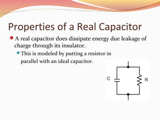
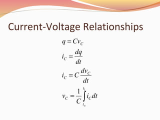
Design SolutionDesign Solution
: Prepared By :k Barot
Energy Storage Devices
Objective of Lecture
Describe the construction of a capacitor and how
charge is stored.
Introduce several types of capacitors
Discuss the electrical properties of a capacitor
The relationship between charge, voltage, and
capacitance
 Charging and discharging of a capacitor
Relationship between voltage, current, and capacitance;
power; and energy
Equivalent capacitance when a set of capacitors are in
series and in parallel
Capacitors
Composed of two conductive plates separated by an
insulator (or dielectric).
Commonly illustrated as two parallel metal plates
separated by a distance, d.
C = ε A/d
where ε = εr εo
εr is the relative dielectric constant
εo is the vacuum permittivity
Effect of Dimensions
Capacitance increases with
increasing surface area of the plates,
decreasing spacing between plates, and
increasing the relative dielectric constant of the
insulator between the two plates.
Types of Capacitors
Fixed Capacitors
Nonpolarized
 May be connected into circuit with either terminal of
capacitor connected to the high voltage side of the circuit.
 Insulator: Paper, Mica, Ceramic, Polymer
Electrolytic
 The negative terminal must always be at a lower voltage than
the positive terminal
 Plates or Electrodes: Aluminum, Tantalum
Nonpolarized
Difficult to make nonpolarized capacitors that store a
large amount of charge or operate at high voltages.
Tolerance on capacitance values is very large
 +50%/-25% is not unusual
http://www.marvac.com/fun/ceramic_capacitor_codes.aspx
PSpice Symbol
Electrical Properties of a Capacitor
Acts like an open circuit at steady state when
connected to a d.c. voltage or current source.
Voltage on a capacitor must be continuous
There are no abrupt changes to the voltage, but there
may be discontinuities in the current.
An ideal capacitor does not dissipate energy, it takes
power when storing energy and returns it when
discharging.
Properties of a Real Capacitor
A real capacitor does dissipate energy due leakage of
charge through its insulator.
This is modeled by putting a resistor in
parallel with an ideal capacitor.
Energy Storage
Charge is stored on the plates of the capacitor.
Equation:
Q = CV
Units:
Farad = Coulomb/Voltage
Farad is abbreviated as F
Sign Conventions
• The sign convention used with a
capacitor is the same as for a power
dissipating device.
• When current flows into the positive side
of the voltage across the capacitor, it is
positive and the capacitor is dissipating
power.
• When the capacitor releases energy back
into the circuit, the sign of the current will
be negative.
Charging a Capacitor
At first, it is easy to store charge in the capacitor.
As more charge is stored on the plates of the
capacitor, it becomes increasingly difficult to place
additional charge on the plates.
Coulombic repulsion from the charge already on the
plates creates an opposing force to limit the addition of
more charge on the plates.
 Voltage across a capacitor increases rapidly as charge is
moved onto the plates when the initial amount of charge on
the capacitor is small.
 Voltage across the capacitor increases more slowly as it
becomes difficult to add extra charge to the plates.
Adding Charge to Capacitor
The ability to add charge to a capacitor depends on:
the amount of charge already on the plates of the
capacitor
and
the force (voltage) driving the charge towards the
plates (i.e., current)
Discharging a Capacitor
At first, it is easy to remove charge in the capacitor.
Coulombic repulsion from charge already on the plates
creates a force that pushes some of the charge out of the
capacitor once the force (voltage) that placed the charge in
the capacitor is removed (or decreased).
As more charge is removed from the plates of the
capacitor, it becomes increasingly difficult to get rid of the
small amount of charge remaining on the plates.
Coulombic repulsion decreases as charge spreads out on the
plates. As the amount of charge decreases, the force needed
to drive the charge off of the plates decreases.
 Voltage across a capacitor decreases rapidly as charge is removed
from the plates when the initial amount of charge on the capacitor
is small.
 Voltage across the capacitor decreases more slowly as it becomes
difficult to force the remaining charge out of the capacitor.
Current-Voltage Relationships
∫=
=
=
=
1
1
t
t
CC
C
C
C
C
o
dti
C
v
dt
dv
Ci
dt
dq
i
Cvq
Power and Energy
dt
dv
Cvp
vip
C
CC
CCC
=
=
C
q
w
Cvw
C
CC
2
2
1
2
2
=
=
Capacitors in Parallel
Ceq for Capacitors in Parallel
i
4321eq
4321
4433
2211
4321
C CCCC
dt
dv
Ci
dt
dv
C
dt
dv
C
dt
dv
C
dt
dv
Ci
dt
dv
Ci
dt
dv
Ci
dt
dv
Ci
dt
dv
Ci
iiiii
eqin
in
in
+++=
=
+++=
==
==
+++=
Capacitors in Series
Ceq for Capacitors in Series
i
( ) ( ) ( ) ( )[ ] 1
4321eq
t
t
t
t4
t
t3
t
t2
t
t1
t
t4
4
t
t3
3
t
t2
2
t
t1
1
4321
1111C
idt
1
idt
1
idt
1
idt
1
idt
1
idt
1
idt
1
idt
1
idt
1
1
o
1
o
1
o
1
o
1
o
1
o
1
o
1
o
1
o
−
+++=
=
+++=
==
==
+++=
∫
∫∫∫∫
∫∫
∫∫
CCCC
C
v
CCCC
v
C
v
C
v
C
v
C
v
vvvvv
eq
in
in
in
General Equations for Ceq
Parallel Combination Series Combination
If P capacitors are in parallel,
then
If S capacitors are in series,
then:
1
1
1
−
=






= ∑
S
s s
eq
C
C∑=
=
P
p
Peq CC
1
Summary
Capacitors are energy storage devices.
An ideal capacitor act like an open circuit at steady state when a
DC voltage or current has been applied.
The voltage across a capacitor must be a continuous function;
the current flowing through a capacitor can be discontinuous.
The equations for equivalent capacitance for
capacitors in parallel capacitors in series
1
1
1
−
=






= ∑
S
s s
eq
C
C∑=
=
P
p
Peq CC
1
∫==
1
1
t
t
CC
C
C
o
dti
C
v
dt
dv
Ci
Keyur be capacitors

Keyur be capacitors

  • 2.
  • 3.
  • 4.
    Objective of Lecture Describethe construction of a capacitor and how charge is stored. Introduce several types of capacitors Discuss the electrical properties of a capacitor The relationship between charge, voltage, and capacitance  Charging and discharging of a capacitor Relationship between voltage, current, and capacitance; power; and energy Equivalent capacitance when a set of capacitors are in series and in parallel
  • 5.
    Capacitors Composed of twoconductive plates separated by an insulator (or dielectric). Commonly illustrated as two parallel metal plates separated by a distance, d. C = ε A/d where ε = εr εo εr is the relative dielectric constant εo is the vacuum permittivity
  • 6.
    Effect of Dimensions Capacitanceincreases with increasing surface area of the plates, decreasing spacing between plates, and increasing the relative dielectric constant of the insulator between the two plates.
  • 7.
    Types of Capacitors FixedCapacitors Nonpolarized  May be connected into circuit with either terminal of capacitor connected to the high voltage side of the circuit.  Insulator: Paper, Mica, Ceramic, Polymer Electrolytic  The negative terminal must always be at a lower voltage than the positive terminal  Plates or Electrodes: Aluminum, Tantalum
  • 8.
    Nonpolarized Difficult to makenonpolarized capacitors that store a large amount of charge or operate at high voltages. Tolerance on capacitance values is very large  +50%/-25% is not unusual http://www.marvac.com/fun/ceramic_capacitor_codes.aspx PSpice Symbol
  • 9.
    Electrical Properties ofa Capacitor Acts like an open circuit at steady state when connected to a d.c. voltage or current source. Voltage on a capacitor must be continuous There are no abrupt changes to the voltage, but there may be discontinuities in the current. An ideal capacitor does not dissipate energy, it takes power when storing energy and returns it when discharging.
  • 10.
    Properties of aReal Capacitor A real capacitor does dissipate energy due leakage of charge through its insulator. This is modeled by putting a resistor in parallel with an ideal capacitor.
  • 11.
    Energy Storage Charge isstored on the plates of the capacitor. Equation: Q = CV Units: Farad = Coulomb/Voltage Farad is abbreviated as F
  • 12.
    Sign Conventions • Thesign convention used with a capacitor is the same as for a power dissipating device. • When current flows into the positive side of the voltage across the capacitor, it is positive and the capacitor is dissipating power. • When the capacitor releases energy back into the circuit, the sign of the current will be negative.
  • 13.
    Charging a Capacitor Atfirst, it is easy to store charge in the capacitor. As more charge is stored on the plates of the capacitor, it becomes increasingly difficult to place additional charge on the plates. Coulombic repulsion from the charge already on the plates creates an opposing force to limit the addition of more charge on the plates.  Voltage across a capacitor increases rapidly as charge is moved onto the plates when the initial amount of charge on the capacitor is small.  Voltage across the capacitor increases more slowly as it becomes difficult to add extra charge to the plates.
  • 14.
    Adding Charge toCapacitor The ability to add charge to a capacitor depends on: the amount of charge already on the plates of the capacitor and the force (voltage) driving the charge towards the plates (i.e., current)
  • 15.
    Discharging a Capacitor Atfirst, it is easy to remove charge in the capacitor. Coulombic repulsion from charge already on the plates creates a force that pushes some of the charge out of the capacitor once the force (voltage) that placed the charge in the capacitor is removed (or decreased). As more charge is removed from the plates of the capacitor, it becomes increasingly difficult to get rid of the small amount of charge remaining on the plates. Coulombic repulsion decreases as charge spreads out on the plates. As the amount of charge decreases, the force needed to drive the charge off of the plates decreases.  Voltage across a capacitor decreases rapidly as charge is removed from the plates when the initial amount of charge on the capacitor is small.  Voltage across the capacitor decreases more slowly as it becomes difficult to force the remaining charge out of the capacitor.
  • 16.
  • 17.
  • 18.
  • 19.
    Ceq for Capacitorsin Parallel i 4321eq 4321 4433 2211 4321 C CCCC dt dv Ci dt dv C dt dv C dt dv C dt dv Ci dt dv Ci dt dv Ci dt dv Ci dt dv Ci iiiii eqin in in +++= = +++= == == +++=
  • 20.
  • 21.
    Ceq for Capacitorsin Series i ( ) ( ) ( ) ( )[ ] 1 4321eq t t t t4 t t3 t t2 t t1 t t4 4 t t3 3 t t2 2 t t1 1 4321 1111C idt 1 idt 1 idt 1 idt 1 idt 1 idt 1 idt 1 idt 1 idt 1 1 o 1 o 1 o 1 o 1 o 1 o 1 o 1 o 1 o − +++= = +++= == == +++= ∫ ∫∫∫∫ ∫∫ ∫∫ CCCC C v CCCC v C v C v C v C v vvvvv eq in in in
  • 22.
    General Equations forCeq Parallel Combination Series Combination If P capacitors are in parallel, then If S capacitors are in series, then: 1 1 1 − =       = ∑ S s s eq C C∑= = P p Peq CC 1
  • 23.
    Summary Capacitors are energystorage devices. An ideal capacitor act like an open circuit at steady state when a DC voltage or current has been applied. The voltage across a capacitor must be a continuous function; the current flowing through a capacitor can be discontinuous. The equations for equivalent capacitance for capacitors in parallel capacitors in series 1 1 1 − =       = ∑ S s s eq C C∑= = P p Peq CC 1 ∫== 1 1 t t CC C C o dti C v dt dv Ci