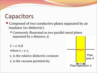
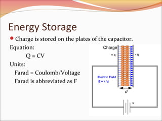
Energy Storage Devices
Objective of Lecture
Describe the construction of a capacitor and how

charge is stored.
Introduce several types of capacitors
Discuss the electrical properties of a capacitor
The relationship between charge, voltage, and

capacitance


Charging and discharging of a capacitor

Relationship between voltage, current, and capacitance;

power; and energy
Equivalent capacitance when a set of capacitors are in
series and in parallel
Capacitors
Composed of two conductive plates separated by an

insulator (or dielectric).

Commonly illustrated as two parallel metal plates

separated by a distance, d.

C = ε A/d
where ε = εr εo
εr is the relative dielectric constant
εo is the vacuum permittivity
Effect of Dimensions
Capacitance increases with
increasing surface area of the plates,
decreasing spacing between plates, and
increasing the relative dielectric constant of the

insulator between the two plates.
Types of Capacitors
Fixed Capacitors
Nonpolarized


May be connected into circuit with either terminal of
capacitor connected to the high voltage side of the circuit.
 Insulator: Paper, Mica, Ceramic, Polymer

Electrolytic


The negative terminal must always be at a lower voltage than
the positive terminal
 Plates or Electrodes: Aluminum, Tantalum
Nonpolarized
Difficult to make nonpolarized capacitors that store a

large amount of charge or operate at high voltages.
Tolerance on capacitance values is very large


+50%/-25% is not unusual
PSpice Symbol

http://www.marvac.com/fun/ceramic_capacitor_codes.a
spx
Electrolytic
Pspice Symbols

Fabrication

http://www.digitivity.com/articles/2008/11/choosing-the-rightcapacitor.html
Variable Capacitors
Cross-sectional area is changed as one set of plates

are rotated with respect to the other.

PSpice Symbol

http://www.tpub.com/neets/book2/3f.htm
MEMS Capacitor
MEMS (Microelectromechanical system)
Can be a variable capacitor by changing the distance

between electrodes.
Use in sensing applications as well as in RF electronics.

http://www.silvaco.com/tech_lib_TCAD/simulationstandard/2005/aug/a3/a3.html
Electric Double Layer Capacitor
Also known as a supercapacitor or ultracapacitor
Used in high voltage/high current applications.


Energy storage for alternate energy systems.

http://en.wikipedia.org/wiki/File:Supercapacitor_diagram.svg
Electrical Properties of a Capacitor
Acts like an open circuit at steady state when

connected to a d.c. voltage or current source.
Voltage on a capacitor must be continuous

There are no abrupt changes to the voltage, but there

may be discontinuities in the current.

An ideal capacitor does not dissipate energy, it takes

power when storing energy and returns it when
discharging.
Properties of a Real Capacitor
A real capacitor does dissipate energy due leakage of

charge through its insulator.

This is modeled by putting a resistor in

parallel with an ideal capacitor.
Energy Storage
Charge is stored on the plates of the capacitor.

Equation:
Q = CV
Units:
Farad = Coulomb/Voltage
Farad is abbreviated as F
Sign Conventions
• The sign convention used with a

capacitor is the same as for a power
dissipating device.
• When current flows into the positive side

of the voltage across the capacitor, it is
positive and the capacitor is dissipating
power.
• When the capacitor releases energy back
into the circuit, the sign of the current will
be negative.
Charging a Capacitor
At first, it is easy to store charge in the capacitor.
As more charge is stored on the plates of the

capacitor, it becomes increasingly difficult to place
additional charge on the plates.
Coulombic repulsion from the charge already on the

plates creates an opposing force to limit the addition of
more charge on the plates.
Voltage across a capacitor increases rapidly as charge is
moved onto the plates when the initial amount of charge on
the capacitor is small.
 Voltage across the capacitor increases more slowly as it
becomes difficult to add extra charge to the plates.

Adding Charge to Capacitor
The ability to add charge to a capacitor depends on:
the amount of charge already on the plates of the

capacitor
and
the force (voltage) driving the charge towards the
plates (i.e., current)
Discharging a Capacitor

At first, it is easy to remove charge in the capacitor.
 Coulombic repulsion from charge already on the plates
creates a force that pushes some of the charge out of the
capacitor once the force (voltage) that placed the charge in
the capacitor is removed (or decreased).
As more charge is removed from the plates of the

capacitor, it becomes increasingly difficult to get rid of the
small amount of charge remaining on the plates.
 Coulombic repulsion decreases as charge spreads out on the

plates. As the amount of charge decreases, the force needed
to drive the charge off of the plates decreases.




Voltage across a capacitor decreases rapidly as charge is removed
from the plates when the initial amount of charge on the capacitor
is small.
Voltage across the capacitor decreases more slowly as it becomes
difficult to force the remaining charge out of the capacitor.
Current-Voltage Relationships
q = CvC
dq
iC =
dt
dvC
iC = C
dt
t1

1
vC = ∫ iC dt
C to
Power and Energy
pC = iC vC
dvC
pC = CvC
dt

1
2
wC = CvC
2
2
q
wC =
2C
Capacitors in Parallel
Ceq for Capacitors in Parallel
iin = i1 + i2 + i3 + i4

dv
dv
i1 = C1
i2 = C2
dt
dt
i
dv
dv
i3 = C3
i4 = C4
dt
dt
dv
dv
dv
dv
iin = C1 + C2
+ C3
+ C4
dt
dt
dt
dt
dv
iin = Ceq
dt
C eq = C1 + C2 + C3 + C4
Capacitors in Series
Ceq for Capacitors in Series
vin = v1 + v2 + v3 + v4
1
v1 =
C1
v3 =

1
C3

1
vin =
C1

t1

1
v2 =
C2

∫ idt

to

t1

i

∫ idt

v4 =

to

t1

1
∫ idt + C2
to

1
vin =
Ceq

t1

t1

∫ idt

to

1
C4

1
∫ idt + C3
to

t1

∫ idt

to

t1

1
∫ idt + C4
to

t1

∫ idt

to

t1

∫ idt

to

C eq = [ (1 C1 ) + (1 C2 ) + (1 C3 ) + (1 C4 ) ]

−1
General Equations for Ceq
Parallel Combination

Series Combination

If P capacitors are in parallel,

If S capacitors are in series,

then

then:

P

Ceq = ∑ C P
p =1

Ceq


1 
= ∑ 
 s =1 C s 
S

−1
Summary
Capacitors are energy storage devices.
An ideal capacitor act like an open circuit at steady state when a

DC voltage or current has been applied.
The voltage across a capacitor must be a continuous function;
the current flowing through a capacitor can be discontinuous.
t

dvC
iC = C
dt

1 1
vC = ∫ iC dt
C to

The equations for equivalent capacitance for

capacitors in parallel

capacitors in series

P

Ceq = ∑ C P
p =1

Ceq


1 
= ∑ 
 s =1 C s 
S

−1

Capacitors

  • 1.
  • 2.
    Objective of Lecture Describethe construction of a capacitor and how charge is stored. Introduce several types of capacitors Discuss the electrical properties of a capacitor The relationship between charge, voltage, and capacitance  Charging and discharging of a capacitor Relationship between voltage, current, and capacitance; power; and energy Equivalent capacitance when a set of capacitors are in series and in parallel
  • 3.
    Capacitors Composed of twoconductive plates separated by an insulator (or dielectric). Commonly illustrated as two parallel metal plates separated by a distance, d. C = ε A/d where ε = εr εo εr is the relative dielectric constant εo is the vacuum permittivity
  • 4.
    Effect of Dimensions Capacitanceincreases with increasing surface area of the plates, decreasing spacing between plates, and increasing the relative dielectric constant of the insulator between the two plates.
  • 5.
    Types of Capacitors FixedCapacitors Nonpolarized  May be connected into circuit with either terminal of capacitor connected to the high voltage side of the circuit.  Insulator: Paper, Mica, Ceramic, Polymer Electrolytic  The negative terminal must always be at a lower voltage than the positive terminal  Plates or Electrodes: Aluminum, Tantalum
  • 6.
    Nonpolarized Difficult to makenonpolarized capacitors that store a large amount of charge or operate at high voltages. Tolerance on capacitance values is very large  +50%/-25% is not unusual PSpice Symbol http://www.marvac.com/fun/ceramic_capacitor_codes.a spx
  • 7.
  • 8.
    Variable Capacitors Cross-sectional areais changed as one set of plates are rotated with respect to the other. PSpice Symbol http://www.tpub.com/neets/book2/3f.htm
  • 9.
    MEMS Capacitor MEMS (Microelectromechanicalsystem) Can be a variable capacitor by changing the distance between electrodes. Use in sensing applications as well as in RF electronics. http://www.silvaco.com/tech_lib_TCAD/simulationstandard/2005/aug/a3/a3.html
  • 10.
    Electric Double LayerCapacitor Also known as a supercapacitor or ultracapacitor Used in high voltage/high current applications.  Energy storage for alternate energy systems. http://en.wikipedia.org/wiki/File:Supercapacitor_diagram.svg
  • 11.
    Electrical Properties ofa Capacitor Acts like an open circuit at steady state when connected to a d.c. voltage or current source. Voltage on a capacitor must be continuous There are no abrupt changes to the voltage, but there may be discontinuities in the current. An ideal capacitor does not dissipate energy, it takes power when storing energy and returns it when discharging.
  • 12.
    Properties of aReal Capacitor A real capacitor does dissipate energy due leakage of charge through its insulator. This is modeled by putting a resistor in parallel with an ideal capacitor.
  • 13.
    Energy Storage Charge isstored on the plates of the capacitor. Equation: Q = CV Units: Farad = Coulomb/Voltage Farad is abbreviated as F
  • 14.
    Sign Conventions • Thesign convention used with a capacitor is the same as for a power dissipating device. • When current flows into the positive side of the voltage across the capacitor, it is positive and the capacitor is dissipating power. • When the capacitor releases energy back into the circuit, the sign of the current will be negative.
  • 15.
    Charging a Capacitor Atfirst, it is easy to store charge in the capacitor. As more charge is stored on the plates of the capacitor, it becomes increasingly difficult to place additional charge on the plates. Coulombic repulsion from the charge already on the plates creates an opposing force to limit the addition of more charge on the plates. Voltage across a capacitor increases rapidly as charge is moved onto the plates when the initial amount of charge on the capacitor is small.  Voltage across the capacitor increases more slowly as it becomes difficult to add extra charge to the plates. 
  • 16.
    Adding Charge toCapacitor The ability to add charge to a capacitor depends on: the amount of charge already on the plates of the capacitor and the force (voltage) driving the charge towards the plates (i.e., current)
  • 17.
    Discharging a Capacitor Atfirst, it is easy to remove charge in the capacitor.  Coulombic repulsion from charge already on the plates creates a force that pushes some of the charge out of the capacitor once the force (voltage) that placed the charge in the capacitor is removed (or decreased). As more charge is removed from the plates of the capacitor, it becomes increasingly difficult to get rid of the small amount of charge remaining on the plates.  Coulombic repulsion decreases as charge spreads out on the plates. As the amount of charge decreases, the force needed to drive the charge off of the plates decreases.   Voltage across a capacitor decreases rapidly as charge is removed from the plates when the initial amount of charge on the capacitor is small. Voltage across the capacitor decreases more slowly as it becomes difficult to force the remaining charge out of the capacitor.
  • 18.
    Current-Voltage Relationships q =CvC dq iC = dt dvC iC = C dt t1 1 vC = ∫ iC dt C to
  • 19.
    Power and Energy pC= iC vC dvC pC = CvC dt 1 2 wC = CvC 2 2 q wC = 2C
  • 20.
  • 21.
    Ceq for Capacitorsin Parallel iin = i1 + i2 + i3 + i4 dv dv i1 = C1 i2 = C2 dt dt i dv dv i3 = C3 i4 = C4 dt dt dv dv dv dv iin = C1 + C2 + C3 + C4 dt dt dt dt dv iin = Ceq dt C eq = C1 + C2 + C3 + C4
  • 22.
  • 23.
    Ceq for Capacitorsin Series vin = v1 + v2 + v3 + v4 1 v1 = C1 v3 = 1 C3 1 vin = C1 t1 1 v2 = C2 ∫ idt to t1 i ∫ idt v4 = to t1 1 ∫ idt + C2 to 1 vin = Ceq t1 t1 ∫ idt to 1 C4 1 ∫ idt + C3 to t1 ∫ idt to t1 1 ∫ idt + C4 to t1 ∫ idt to t1 ∫ idt to C eq = [ (1 C1 ) + (1 C2 ) + (1 C3 ) + (1 C4 ) ] −1
  • 24.
    General Equations forCeq Parallel Combination Series Combination If P capacitors are in parallel, If S capacitors are in series, then then: P Ceq = ∑ C P p =1 Ceq  1  = ∑   s =1 C s  S −1
  • 25.
    Summary Capacitors are energystorage devices. An ideal capacitor act like an open circuit at steady state when a DC voltage or current has been applied. The voltage across a capacitor must be a continuous function; the current flowing through a capacitor can be discontinuous. t dvC iC = C dt 1 1 vC = ∫ iC dt C to The equations for equivalent capacitance for capacitors in parallel capacitors in series P Ceq = ∑ C P p =1 Ceq  1  = ∑   s =1 C s  S −1