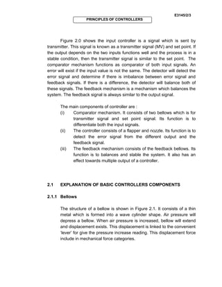
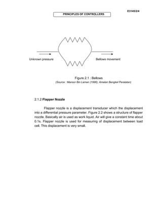
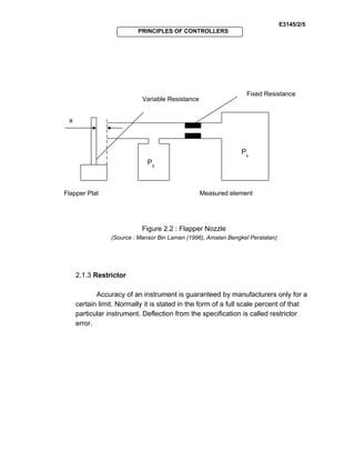
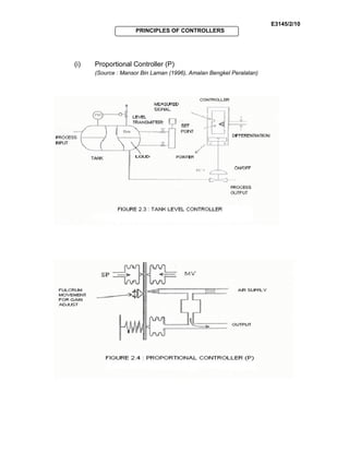
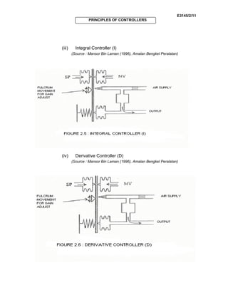
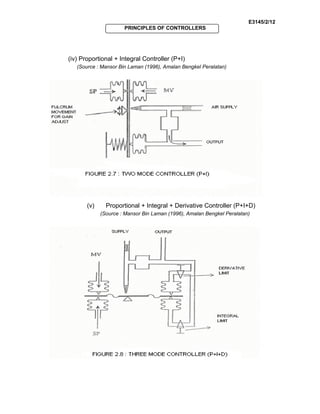
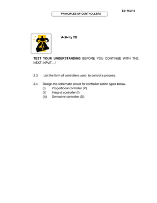
SlideShare a Scribd company logo
E3145/2/1
PRINCIPLES OF CONTROLLERS
OBJECTIVES
General Objective : To apply the concept of principles of controllers.
Specific Objectives : At the end of the unit you will be able to :
 Explain the basic concept of principles of controllers.
 State the definition of basic controller components.
 Draw the schematic circuits for controller action types.
 Explain the circuits operations.
UNIT2
E3145/2/2
PRINCIPLES OF CONTROLLERS
2.0 EXPLANATION OF PRINCIPLES OF BASIC CONTROLLERS
Controller is a device which receives input from two points :
(i) a value which is sent by transmitter
(ii) a value which is set by set point
The output from the controller is send to the valve controller.
Figure 2.0 : Block Diagram of controller
(Source : Mansor Bin Laman (1996), Amalan Bengkel Peralatan)
INPUTINPUT
The main component of
controller are :
Comparator mechanism
Controller
Feedback mechanism
Comparator
mechanism
Feedback
mechanism
Relay
Sensor
MV
SP
Output
Supply
E3145/2/3
PRINCIPLES OF CONTROLLERS
Figure 2.0 shows the input controller is a signal which is sent by
transmitter. This signal is known as a transmitter signal (MV) and set point. If
the output depends on the two inputs functions well and the process is in a
stable condition, then the transmitter signal is similar to the set point. The
comparator mechanism functions as comparator of both input signals. An
error will exist if the input value is not the same. The detector will detect the
error signal and determine if there is imbalance between error signal and
feedback signals. If there is a difference, the detector will balance both of
these signals. The feedback mechanism is a mechanism which balances the
system. The feedback signal is always similar to the output signal.
The main components of controller are :
(i) Comparator mechanism. It consists of two bellows which is for
transmitter signal and set point signal. Its function is to
differentiate both the input signals.
(ii) The controller consists of a flapper and nozzle. Its function is to
detect the error signal from the different output and the
feedback signal.
(iii) The feedback mechanism consists of the feedback bellows. Its
function is to balances and stable the system. It also has an
effect towards multiple output of a controller.
2.1 EXPLANATION OF BASIC CONTROLLERS COMPONENTS
2.1.1 Bellows
The structure of a bellow is shown in Figure 2.1. It consists of a thin
metal which is formed into a wave cylinder shape. Air pressure will
depress a bellow. When air pressure is increased, bellow will extend
and displacement exists. This displacement is linked to the convenient
‘lever’ for give the pressure increase reading. This displacement force
include in mechanical force categories.
E3145/2/4
PRINCIPLES OF CONTROLLERS
Figure 2.1 : Bellows
(Source : Mansor Bin Laman (1996), Amalan Bengkel Peralatan)
2.1.2 Flapper Nozzle
Flapper nozzle is a displacement transducer which the displacement
into a differential pressure parameter. Figure 2.2 shows a structure of flapper
nozzle. Basically air is used as work liquid. Air will give a constant time about
0.1s. Flapper nozzle is used for measuring of displacement between load
cell. This displacement is very small.
Unknown pressure Bellows movement
E3145/2/5
PRINCIPLES OF CONTROLLERS
Figure 2.2 : Flapper Nozzle
(Source : Mansor Bin Laman (1996), Amalan Bengkel Peralatan)
2.1.3 Restrictor
Accuracy of an instrument is guaranteed by manufacturers only for a
certain limit. Normally it is stated in the form of a full scale percent of that
particular instrument. Deflection from the specification is called restrictor
error.
Fixed Resistance
Variable Resistance
x
Flapper Plat Measured element
Ρ0
Ρs
E3145/2/6
PRINCIPLES OF CONTROLLERS
Activity 2A
TEST YOUR UNDERSTANDING BEFORE YOU CONTINUE WITH THE
NEXT INPUT…!
2.1 Explain the basic controllers components below:
(i) Bellows
(ii) Flapper nozzle
2.2 Draw the diagram of bellow and flapper nozzle.
E3145/2/7
PRINCIPLES OF CONTROLLERS
Feedback To Activity 2A
2.1. (i) Bellows consists of a thin metal which is formed into a wave
cylinder shape. Air pressure will depress a bellow. When air pressure
is increased, bellows will extend and displacement exists. This
displacement is linked to convenient ‘ lever ’ for give the pressure
increase reading. This displacement force include in mechanical force
categories.
(ii) Flapper nozzle is a displacement transducer which the
displacement into a differential pressure parameter. Basically air is
used as work liquid. Air will give a constant time about 0.1s. Flapper
nozzle is used for measuring of displacement between load cell. This
displacement is very small.
2.2 (i) Bellows
Unknown pressure Bellows movement
E3145/2/8
PRINCIPLES OF CONTROLLERS
(ii) Flapper nozzle
Fixed Resistance
Variable Resistance
x
Flapper Plat Measured element
Ρ0
Ρs
E3145/2/9
PRINCIPLES OF CONTROLLERS
2.2DESIGN OF SCHEMATIC CIRCUIT FOR CONTROLLER ACTION TYPES
2.2.1 Types of Controller
There are a few types of controller used to control a process either in
a form of Proportional output to the error, Proportional and Integral to the
error or Proportional and Derivative output to the first error.
Controller can be used in the form of single mode of Proportional,
Integral, or Derivative, two mode of Proportional and Integral (P+I) and
Proportional and Derivative (P+D), and three mode of Proportional, Integral
and Derivative (P+I+D).
The figures below show the design of schematic circuit for controller
action types.
There are three types of
controller :
a) Proportional
controller
b) Integral controller
c) Derivative controller
INPUTINPUT
E3145/2/10
PRINCIPLES OF CONTROLLERS
(i) Proportional Controller (P)
(Source : Mansor Bin Laman (1996), Amalan Bengkel Peralatan)
E3145/2/11
PRINCIPLES OF CONTROLLERS
(iii) Integral Controller (I)
(Source : Mansor Bin Laman (1996), Amalan Bengkel Peralatan)
(iv) Derivative Controller (D)
(Source : Mansor Bin Laman (1996), Amalan Bengkel Peralatan)
E3145/2/12
PRINCIPLES OF CONTROLLERS
(iv) Proportional + Integral Controller (P+I)
(Source : Mansor Bin Laman (1996), Amalan Bengkel Peralatan)
(v) Proportional + Integral + Derivative Controller (P+I+D)
(Source : Mansor Bin Laman (1996), Amalan Bengkel Peralatan)
E3145/2/13
PRINCIPLES OF CONTROLLERS
Activity 2B
TEST YOUR UNDERSTANDING BEFORE YOU CONTINUE WITH THE
NEXT INPUT…!
2.3 List the form of controllers used to control a process.
2.4 Design the schematic circuit for controller action types below.
(i) Proportional controller (P)
(ii) Integral controller (I)
(iii) Derivative controller (D)
E3145/2/14
PRINCIPLES OF CONTROLLERS
Feedback To Activity 2B
2.3 Controller can be used in the form of
(a) Single mode of Proportional, Integral, or Derivative
(b) Two mode of Proportional and Integral (P+I) and Proportional
Derivative (P+D)
(c) Three mode of Proportional, Integral and Derivative (P+I+D).
2.4 (i)
E3145/2/15
PRINCIPLES OF CONTROLLERS
(ii)
(iii)
E3145/2/16
PRINCIPLES OF CONTROLLERS
2.3 EXPLANATION OF CIRCUITS OPERATION
2.3.1 Proportional Controller (P)
This controller can be found in Proportional controller where the output is
always proportional to the error ( e ) signal. If the error signal is small, the control
action will also be small and if the error signal is high, the control action will also be
high. Once the controller detects an error, it will start to act. Output depends on
controller gain, kc i.e.
controller output = controller gain x error
Figure 2.4 (see INPUT 2.2) shows, when measured signal equals to the set point,
the system is stable. In other words, if the input process is equal to the output
process, a stable system is obtained. If the Proportional controller is used there will
be an offset where the measured signal will not reach the set point. Therefore if the
control valve has to be 50% opened, we need to open the control valve more than
50% to achieve stability.
2.3.2 Integral Controller (I)
Integral controller responses to the integration of error signal to time. So,
output is proportional to the area below the curve with time,
Controller output α ∫ t
e dt
In Figure 2.6 (see INPUT 2.2), bellows and spring are in the reverse position
compared to Proportional controller in Figure 2.5.
INPUTINPUT
E3145/2/17
PRINCIPLES OF CONTROLLERS
2.3.3 Derivative Controller (D)
Derivative controller reacts to the rate of change but not to the change of
magnitude. Output is proportional to the derivation error signal (e) to time,
Controller output α de
dt
If error is not changing or fixed there will be no output. Derivative controller is shown
in Figure 2.7 (see INPUT 2.2). Derivative controller has one limit which is known as
Derivative Limit. This limit distinguishes Proportional Controller and Derivative
Controller. In a stable condition the derivative controller does not affect the output
and it is always used in the process where temperature is involved.
As a conclusion, if we want a fast controller, then the Proportional controller
is better but offset will occur. However, if we want to reduce offset, the Derivative
controller can be used and we want to eliminate it, then the Integral controller
should used.
2.3.4 Two Mode Control System (Proportional and Integral Controller)
The Figure 2.8 (see INPUT 2.2) shows a basic concept of a two mode
control system. The comparator mechanism (which consists of two bellows) is place
on one end of lever while on the other end there are two feedback bellows. A
sensor is placed between the feedback mechanism and comparator. The operation
of a two mode control system is different from a single mode control system
because it combines the action of either both Proportional controller or Integral
controller only.
Based on Figure 2.8, two things are added to the controller i.e. Integral/
Reset bellows and Integral limit (adjustable). When measured signal is increased,
force impedance will come closer to the nozzle and thus will increase output.
Increased pressure will make proportional bellow change the position of force
impedance hence stabilize output pressure. Pressure will drop when it passes
through integration unit. This pressure will pass integration bellow and push force
impedance closer to the nozzle. So, output pressure can be increased further.
E3145/2/18
PRINCIPLES OF CONTROLLERS
A stable system will be achieved when measured signal is equal to the set
point and output pressure will be stable. Thus, offset can be eliminated. If a stable
system cannot be achieved, the integration limit can be adjusted. If the integration
limit is fully opened, the controller will act as an ON/OFF Controller. If integration
limit is fully closed, the controller will act as a Proportional controller only.
2.3.5 Three Mode Controller System (P+I+D)
Figure 2.9 (see INPUT 2.2), shows three mode controller system. The
operation is similar to P+I Controller but with the addition of a derivative limit. For
this system, all controllers (Proportional, Integral and Derivative) will affect the
responses. So, we need to adjust every controller to suit the process. Adjustments
need to be done individually to stabilize process and eliminate offset. To achieve
that, integral limit and derivative limit must be adjusted correctly.
2.3.6 Advantages and Disadvantages
Controllers have advantages and disadvantages. Table 2.1 below shows the
advantages and disadvantages of a single and two mode controller.
CONTROLLER ADVANTAGES DISADVANTAGES
Proportional Faster response when
load is changing
Offset exist
Integral Eliminate offset Longer recovery time
Derivative Reduce offset No output when no error
Proportional + Derivative Reduce recovery time and
offset
Offset still occurs
Proportional + Integral Can eliminate offset Longer recovery time
Table 2.1
(Source : Mansor Bin Laman (1996), Amalan Bengkel Peralatan)
E3145/2/19
PRINCIPLES OF CONTROLLERS
Activity 2C
TEST YOUR UNDERSTANDING BEFORE YOU CONTINUE WITH THE
NEXT INPUT…!
2.5 Draw a suitable figure and explain a basic concept of a two mode
control system (Proportional and Integral controller)
2.6 Give the advantages and disadvantages of Proportional, Integral,
Derivative, Proportional + Derivative and Proportional + Integral.
E3145/2/20
PRINCIPLES OF CONTROLLERS
Feedback To Activity 2c
2.5
Based on Figure 2.12, two things are added to the controller i.e.
Integral/ Reset bellows and Integral limit (adjustable). When measured signal
is increased, force impedance will come closer to the nozzle and thus will
increase output. Increased pressure will make proportional bellow change
the position of force impedance hence stabilize output pressure. Pressure
will drop when it passes through integration unit. This pressure will pass
integration bellow and push force impedance closer to the nozzle. So, output
pressure can be increased further.
E3145/2/21
PRINCIPLES OF CONTROLLERS
A stable system will be achieved when measured signal is equal to
the set point and output pressure will be stable. Thus, offset can be
eliminated. If a stable system cannot be achieved, the integration limit can be
adjusted. If the integration limit is fully opened, the controller will act as an
ON/OFF Controller. If integration limit is fully closed, the controller will act as
a Proportional controller only.
2.6 Advantages and Disadvantages
CONTROLLER ADVANTAGES DISADVANTAGES
Proportional Faster response when
load is changing
Offset exist
Integral Eliminate offset Longer recovery time
Derivative Reduce offset No output when no error
Proportional +
Derivative
Reduce recovery time and
offset
Offset still occurs
Proportional +
Integral
Can eliminate offset Longer recovery time
E3145/2/22
PRINCIPLES OF CONTROLLERS
KEY FACTS
1. Controller can be used in the form of single mode of Proportional,
Integral, or Derivative, two mode of Proportional and Integral
(P+I) and Proportional and Derivative (P+D), and three mode of
Proportional, Integral and Derivative (P+I+D).
2. Proportional controller (P)
Output depends on controller gain, kc i.e.
Controller output = controller gain x error
3. Integral controller (I)
Output is proportional to the area below the curve with time,
Controller output α ∫ t
e dt
4. Derivative controller (D)
Output is proportional to the derivation error signal (e) to time,
Controller output α de
dt
E3145/2/23
PRINCIPLES OF CONTROLLERS
SELF-ASSESSMENT
You are approaching success. Try all the questions in this self-assessment
section and check your answers with those given in the Feedback on Self-
Assessment given on the next page. If you face any problems, discuss it
with your lecturer. Good luck.
Q2-1 State the definition of restrictor.
Q2-2 Design the schematic circuit for controller action types below.
(i) P+I
(II) P+I+D
Q2-3
(a) State the difference between two mode control system and single
mode system.
(b) Explain the operation of three mode controller system (P+I+D)
E3145/2/24
PRINCIPLES OF CONTROLLERS
Feedback To Self-Assessment
Have you tried the questions????? If “YES”, check your answers now.
Q2-1 Accuracy of an instrument is guaranteed by manufacturers only for a
certain limit. Normally it is stated in the form of a full scale percent of
that particular instrument. Deflection from the specification is called
restrictor error.
Q2-2 (i) P+I
E3145/2/25
PRINCIPLES OF CONTROLLERS
(ii) P+I+D
Q2-3
(a) The operation of two mode control system is different to single mode
control system because it combine the action of either both
Proportional controller or Integral controller only.
(b) The operation of P+I+D controller is similar to P+I Controller but with
the addition of derivative limit. For this system, all controllers
(Proportional, Integral and Derivative) will affect the response. So, we
need to adjust every controller to suit the process. Adjustment need to
be done individually to stabilize process and eliminate offset. To
achieve that, integral limit and derivative limit must be adjusted
correctly.
E3145/2/26
PRINCIPLES OF CONTROLLERS

More Related Content

What's hot

Chapter 1 Automatic Controloverview
Chapter 1 Automatic ControloverviewChapter 1 Automatic Controloverview
Chapter 1 Automatic Controloverview
Water Birds (Ali)
 
Control systems engineering
Control systems engineeringControl systems engineering
Control systems engineering
Anisur Rahman
 
Introduction to control systems
Introduction to control systems Introduction to control systems
Introduction to control systems
Hendi Saryanto
 
Control Systems Basics
Control Systems BasicsControl Systems Basics
Control Systems Basics
John Todora
 
Introduction to Control System Design
Introduction to Control System DesignIntroduction to Control System Design
Introduction to Control System Design
Andrew Wilhelm
 
Chapter 1 introduction to control system
Chapter 1 introduction to control systemChapter 1 introduction to control system
Chapter 1 introduction to control system
LenchoDuguma
 
Introduction to control system 2
Introduction to control system 2Introduction to control system 2
Introduction to control system 2
turna67
 
Control
ControlControl
BEC 26 control-Systems_unit-I_pdf
BEC 26 control-Systems_unit-I_pdfBEC 26 control-Systems_unit-I_pdf
BEC 26 control-Systems_unit-I_pdf
Shadab Siddiqui
 
Control systems
Control systems Control systems
Control systems
Dr.YNM
 
Lecture 1 the lecture
Lecture 1   the lectureLecture 1   the lecture
Lecture 1 the lecture
Mohd Khairi Mohamed Nor
 
Cascade control of superheated steam temperature with neuro PID controller
Cascade control of superheated steam temperature with neuro PID controllerCascade control of superheated steam temperature with neuro PID controller
Cascade control of superheated steam temperature with neuro PID controller
ISA Interchange
 
Control system unit(1)
Control system unit(1)Control system unit(1)
Control system unit(1)
Mohammed Waris Senan
 
Control system basics_open and closed loop control system
Control system basics_open and closed loop control systemControl system basics_open and closed loop control system
Control system basics_open and closed loop control system
Nilesh Bhaskarrao Bahadure
 
Lecture2(introduction)
Lecture2(introduction)Lecture2(introduction)
Lecture2(introduction)
Razali Tomari
 
Control system
Control systemControl system
Control system
swathisriranjani1
 
Control System Design
Control System DesignControl System Design
Control System Design
Hitesh Sharma
 
Process control 2 chapter
Process control 2 chapterProcess control 2 chapter
Process control 2 chapter
Srinivasa Rao
 
Pe 3032 wk 1 introduction to control system march 04e
Pe 3032 wk 1 introduction to control system  march 04ePe 3032 wk 1 introduction to control system  march 04e
Pe 3032 wk 1 introduction to control system march 04e
Charlton Inao
 
Control system basics, block diagram and signal flow graph
Control system basics, block diagram and signal flow graphControl system basics, block diagram and signal flow graph
Control system basics, block diagram and signal flow graph
SHARMA NAVEEN
 

What's hot (20)

Chapter 1 Automatic Controloverview
Chapter 1 Automatic ControloverviewChapter 1 Automatic Controloverview
Chapter 1 Automatic Controloverview
 
Control systems engineering
Control systems engineeringControl systems engineering
Control systems engineering
 
Introduction to control systems
Introduction to control systems Introduction to control systems
Introduction to control systems
 
Control Systems Basics
Control Systems BasicsControl Systems Basics
Control Systems Basics
 
Introduction to Control System Design
Introduction to Control System DesignIntroduction to Control System Design
Introduction to Control System Design
 
Chapter 1 introduction to control system
Chapter 1 introduction to control systemChapter 1 introduction to control system
Chapter 1 introduction to control system
 
Introduction to control system 2
Introduction to control system 2Introduction to control system 2
Introduction to control system 2
 
Control
ControlControl
Control
 
BEC 26 control-Systems_unit-I_pdf
BEC 26 control-Systems_unit-I_pdfBEC 26 control-Systems_unit-I_pdf
BEC 26 control-Systems_unit-I_pdf
 
Control systems
Control systems Control systems
Control systems
 
Lecture 1 the lecture
Lecture 1   the lectureLecture 1   the lecture
Lecture 1 the lecture
 
Cascade control of superheated steam temperature with neuro PID controller
Cascade control of superheated steam temperature with neuro PID controllerCascade control of superheated steam temperature with neuro PID controller
Cascade control of superheated steam temperature with neuro PID controller
 
Control system unit(1)
Control system unit(1)Control system unit(1)
Control system unit(1)
 
Control system basics_open and closed loop control system
Control system basics_open and closed loop control systemControl system basics_open and closed loop control system
Control system basics_open and closed loop control system
 
Lecture2(introduction)
Lecture2(introduction)Lecture2(introduction)
Lecture2(introduction)
 
Control system
Control systemControl system
Control system
 
Control System Design
Control System DesignControl System Design
Control System Design
 
Process control 2 chapter
Process control 2 chapterProcess control 2 chapter
Process control 2 chapter
 
Pe 3032 wk 1 introduction to control system march 04e
Pe 3032 wk 1 introduction to control system  march 04ePe 3032 wk 1 introduction to control system  march 04e
Pe 3032 wk 1 introduction to control system march 04e
 
Control system basics, block diagram and signal flow graph
Control system basics, block diagram and signal flow graphControl system basics, block diagram and signal flow graph
Control system basics, block diagram and signal flow graph
 

Viewers also liked

Basic Control System unit4
Basic Control System unit4Basic Control System unit4
Basic Control System unit4
Asraf Malik
 
Basic Control System unit6
Basic Control System unit6Basic Control System unit6
Basic Control System unit6
Asraf Malik
 
TIME DOMAIN ANALYSIS
TIME DOMAIN ANALYSISTIME DOMAIN ANALYSIS
TIME DOMAIN ANALYSIS
Syed Saeed
 
Lab02 lead in
Lab02 lead inLab02 lead in
Lab02 lead in
John Todora
 
Time domain specifications of second order system
Time domain specifications of second order systemTime domain specifications of second order system
Time domain specifications of second order system
Syed Saeed
 
Time response second order
Time response second orderTime response second order
Time response second order
Syed Saeed
 
Performance of second order system
Performance of second order systemPerformance of second order system
Performance of second order system
Trupesh Rupareliya
 
ControlLogix Timers FA16
ControlLogix Timers FA16ControlLogix Timers FA16
ControlLogix Timers FA16
John Todora
 
Pembuatan trainer input output mikroprosesor sebagai pengajaran praktik pener...
Pembuatan trainer input output mikroprosesor sebagai pengajaran praktik pener...Pembuatan trainer input output mikroprosesor sebagai pengajaran praktik pener...
Pembuatan trainer input output mikroprosesor sebagai pengajaran praktik pener...
Miko Eljava
 
TIME RESPONSE ANALYSIS
TIME RESPONSE ANALYSISTIME RESPONSE ANALYSIS
TIME RESPONSE ANALYSIS
Syed Saeed
 
Time response analysis of system
Time response analysis of systemTime response analysis of system
Time response analysis of system
vishalgohel12195
 
E4141 sistem kawalan 1 unit7
E4141 sistem kawalan 1 unit7E4141 sistem kawalan 1 unit7
E4141 sistem kawalan 1 unit7Asraf Malik
 
E4141 sistem kawalan 1 unit4
E4141 sistem kawalan 1 unit4E4141 sistem kawalan 1 unit4
E4141 sistem kawalan 1 unit4Asraf Malik
 
E4141 sistem kawalan 1 unit9
E4141 sistem kawalan 1 unit9E4141 sistem kawalan 1 unit9
E4141 sistem kawalan 1 unit9
Asraf Malik
 
E4141 sistem kawalan 1 unit5
E4141 sistem kawalan 1 unit5E4141 sistem kawalan 1 unit5
E4141 sistem kawalan 1 unit5
Asraf Malik
 
Lecture 6 ME 176 2 Time Response
Lecture 6 ME 176 2 Time ResponseLecture 6 ME 176 2 Time Response
Lecture 6 ME 176 2 Time Response
Leonides De Ocampo
 
Lecture 2
Lecture 2Lecture 2
Lecture 2
Forward2025
 
JF608: Quality Control - Unit 6
JF608: Quality Control - Unit 6JF608: Quality Control - Unit 6
JF608: Quality Control - Unit 6
Asraf Malik
 
Chapter 4 time domain analysis
Chapter 4 time domain analysisChapter 4 time domain analysis
Chapter 4 time domain analysis
Bin Biny Bino
 
Control chap4
Control chap4Control chap4
Control chap4
Mohd Ashraf Shabarshah
 

Viewers also liked (20)

Basic Control System unit4
Basic Control System unit4Basic Control System unit4
Basic Control System unit4
 
Basic Control System unit6
Basic Control System unit6Basic Control System unit6
Basic Control System unit6
 
TIME DOMAIN ANALYSIS
TIME DOMAIN ANALYSISTIME DOMAIN ANALYSIS
TIME DOMAIN ANALYSIS
 
Lab02 lead in
Lab02 lead inLab02 lead in
Lab02 lead in
 
Time domain specifications of second order system
Time domain specifications of second order systemTime domain specifications of second order system
Time domain specifications of second order system
 
Time response second order
Time response second orderTime response second order
Time response second order
 
Performance of second order system
Performance of second order systemPerformance of second order system
Performance of second order system
 
ControlLogix Timers FA16
ControlLogix Timers FA16ControlLogix Timers FA16
ControlLogix Timers FA16
 
Pembuatan trainer input output mikroprosesor sebagai pengajaran praktik pener...
Pembuatan trainer input output mikroprosesor sebagai pengajaran praktik pener...Pembuatan trainer input output mikroprosesor sebagai pengajaran praktik pener...
Pembuatan trainer input output mikroprosesor sebagai pengajaran praktik pener...
 
TIME RESPONSE ANALYSIS
TIME RESPONSE ANALYSISTIME RESPONSE ANALYSIS
TIME RESPONSE ANALYSIS
 
Time response analysis of system
Time response analysis of systemTime response analysis of system
Time response analysis of system
 
E4141 sistem kawalan 1 unit7
E4141 sistem kawalan 1 unit7E4141 sistem kawalan 1 unit7
E4141 sistem kawalan 1 unit7
 
E4141 sistem kawalan 1 unit4
E4141 sistem kawalan 1 unit4E4141 sistem kawalan 1 unit4
E4141 sistem kawalan 1 unit4
 
E4141 sistem kawalan 1 unit9
E4141 sistem kawalan 1 unit9E4141 sistem kawalan 1 unit9
E4141 sistem kawalan 1 unit9
 
E4141 sistem kawalan 1 unit5
E4141 sistem kawalan 1 unit5E4141 sistem kawalan 1 unit5
E4141 sistem kawalan 1 unit5
 
Lecture 6 ME 176 2 Time Response
Lecture 6 ME 176 2 Time ResponseLecture 6 ME 176 2 Time Response
Lecture 6 ME 176 2 Time Response
 
Lecture 2
Lecture 2Lecture 2
Lecture 2
 
JF608: Quality Control - Unit 6
JF608: Quality Control - Unit 6JF608: Quality Control - Unit 6
JF608: Quality Control - Unit 6
 
Chapter 4 time domain analysis
Chapter 4 time domain analysisChapter 4 time domain analysis
Chapter 4 time domain analysis
 
Control chap4
Control chap4Control chap4
Control chap4
 

Similar to Basic Control System unit2

Week 14 pid may 24 2016 pe 3032
Week  14 pid  may 24 2016 pe 3032Week  14 pid  may 24 2016 pe 3032
Week 14 pid may 24 2016 pe 3032
Charlton Inao
 
Design and tuning of pid override control system based on signal filtering
Design and tuning of pid override control system based on signal filteringDesign and tuning of pid override control system based on signal filtering
Design and tuning of pid override control system based on signal filtering
Minh Chien Tran
 
Modul pneumatic
Modul pneumaticModul pneumatic
Modul pneumatic
dwi kurniawan
 
Pneumatics Circuits Components (Circuit details)
Pneumatics Circuits Components (Circuit details)Pneumatics Circuits Components (Circuit details)
Pneumatics Circuits Components (Circuit details)
S K
 
Design and tuning of PID override control system based on signal filtering
Design and tuning of PID override control system based on signal filteringDesign and tuning of PID override control system based on signal filtering
Design and tuning of PID override control system based on signal filtering
Minh Chien Tran
 
Lecture13
Lecture13Lecture13
Lecture13
sriamrish
 
Basicontrol
BasicontrolBasicontrol
PLC BASIC KASNDKNKNDNNDKNDJWEJFBOEJBFO.ppt
PLC BASIC KASNDKNKNDNNDKNDJWEJFBOEJBFO.pptPLC BASIC KASNDKNKNDNNDKNDJWEJFBOEJBFO.ppt
PLC BASIC KASNDKNKNDNNDKNDJWEJFBOEJBFO.ppt
itsni2
 
C0325010015
C0325010015C0325010015
C0325010015
theijes
 
Meeting w1 chapter 1
Meeting w1   chapter 1Meeting w1   chapter 1
Meeting w1 chapter 1
Hattori Sidek
 
Real-time PID control of an inverted pendulum
Real-time PID control of an inverted pendulumReal-time PID control of an inverted pendulum
Real-time PID control of an inverted pendulum
Francesco Corucci
 
Basicpidcontrol
BasicpidcontrolBasicpidcontrol
Basicpidcontrol
Sheratul Ashikin
 
Fulltext 1005224
Fulltext 1005224 Fulltext 1005224
Fulltext 1005224
EdgarIsmaelReyesDeza
 
PID controller in control systems
PID controller in control systemsPID controller in control systems
PID controller in control systems
khalaf Gaeid
 
E1803033337
E1803033337E1803033337
E1803033337
IOSR Journals
 
ME416A_Module 1.pdf
ME416A_Module 1.pdfME416A_Module 1.pdf
ME416A_Module 1.pdf
MECHANICALENGINEERIN55
 
Time Response
Time ResponseTime Response
Time Response
Syed Saeed
 
Maintopik3
Maintopik3Maintopik3
Maintopik3
Fadzilah Hashim
 
Maintopik3
Maintopik3Maintopik3
Maintopik3
Fadzilah Hashim
 
Lecture Notes: EEEC4340318 Instrumentation and Control Systems - Introductio...
Lecture Notes:  EEEC4340318 Instrumentation and Control Systems - Introductio...Lecture Notes:  EEEC4340318 Instrumentation and Control Systems - Introductio...
Lecture Notes: EEEC4340318 Instrumentation and Control Systems - Introductio...
AIMST University
 

Similar to Basic Control System unit2 (20)

Week 14 pid may 24 2016 pe 3032
Week  14 pid  may 24 2016 pe 3032Week  14 pid  may 24 2016 pe 3032
Week 14 pid may 24 2016 pe 3032
 
Design and tuning of pid override control system based on signal filtering
Design and tuning of pid override control system based on signal filteringDesign and tuning of pid override control system based on signal filtering
Design and tuning of pid override control system based on signal filtering
 
Modul pneumatic
Modul pneumaticModul pneumatic
Modul pneumatic
 
Pneumatics Circuits Components (Circuit details)
Pneumatics Circuits Components (Circuit details)Pneumatics Circuits Components (Circuit details)
Pneumatics Circuits Components (Circuit details)
 
Design and tuning of PID override control system based on signal filtering
Design and tuning of PID override control system based on signal filteringDesign and tuning of PID override control system based on signal filtering
Design and tuning of PID override control system based on signal filtering
 
Lecture13
Lecture13Lecture13
Lecture13
 
Basicontrol
BasicontrolBasicontrol
Basicontrol
 
PLC BASIC KASNDKNKNDNNDKNDJWEJFBOEJBFO.ppt
PLC BASIC KASNDKNKNDNNDKNDJWEJFBOEJBFO.pptPLC BASIC KASNDKNKNDNNDKNDJWEJFBOEJBFO.ppt
PLC BASIC KASNDKNKNDNNDKNDJWEJFBOEJBFO.ppt
 
C0325010015
C0325010015C0325010015
C0325010015
 
Meeting w1 chapter 1
Meeting w1   chapter 1Meeting w1   chapter 1
Meeting w1 chapter 1
 
Real-time PID control of an inverted pendulum
Real-time PID control of an inverted pendulumReal-time PID control of an inverted pendulum
Real-time PID control of an inverted pendulum
 
Basicpidcontrol
BasicpidcontrolBasicpidcontrol
Basicpidcontrol
 
Fulltext 1005224
Fulltext 1005224 Fulltext 1005224
Fulltext 1005224
 
PID controller in control systems
PID controller in control systemsPID controller in control systems
PID controller in control systems
 
E1803033337
E1803033337E1803033337
E1803033337
 
ME416A_Module 1.pdf
ME416A_Module 1.pdfME416A_Module 1.pdf
ME416A_Module 1.pdf
 
Time Response
Time ResponseTime Response
Time Response
 
Maintopik3
Maintopik3Maintopik3
Maintopik3
 
Maintopik3
Maintopik3Maintopik3
Maintopik3
 
Lecture Notes: EEEC4340318 Instrumentation and Control Systems - Introductio...
Lecture Notes:  EEEC4340318 Instrumentation and Control Systems - Introductio...Lecture Notes:  EEEC4340318 Instrumentation and Control Systems - Introductio...
Lecture Notes: EEEC4340318 Instrumentation and Control Systems - Introductio...
 

More from Asraf Malik

JF608: Quality Control - Unit 5
JF608: Quality Control - Unit 5JF608: Quality Control - Unit 5
JF608: Quality Control - Unit 5
Asraf Malik
 
Mechanical Component and Maintenance
Mechanical Component and MaintenanceMechanical Component and Maintenance
Mechanical Component and Maintenance
Asraf Malik
 
JF608: Quality Control - Unit 4
JF608: Quality Control - Unit 4JF608: Quality Control - Unit 4
JF608: Quality Control - Unit 4
Asraf Malik
 
JF608: Quality Control - Unit 3
JF608: Quality Control - Unit 3JF608: Quality Control - Unit 3
JF608: Quality Control - Unit 3
Asraf Malik
 
JF608: Quality Control - Unit 2
JF608: Quality Control - Unit 2JF608: Quality Control - Unit 2
JF608: Quality Control - Unit 2
Asraf Malik
 
JF608: Quality Control - Unit 1
JF608: Quality Control - Unit 1JF608: Quality Control - Unit 1
JF608: Quality Control - Unit 1
Asraf Malik
 
Basic Control System unit0
Basic Control System unit0Basic Control System unit0
Basic Control System unit0
Asraf Malik
 
MATERIAL TECHNOLOGY - CHAPTER 7
MATERIAL TECHNOLOGY  - CHAPTER 7MATERIAL TECHNOLOGY  - CHAPTER 7
MATERIAL TECHNOLOGY - CHAPTER 7
Asraf Malik
 
MATERIAL TECHNOLOGY - CHAPTER 8
MATERIAL TECHNOLOGY - CHAPTER 8MATERIAL TECHNOLOGY - CHAPTER 8
MATERIAL TECHNOLOGY - CHAPTER 8
Asraf Malik
 
MATERIAL TECHNOLOGY 2 - CHAPTER 6
MATERIAL TECHNOLOGY 2 - CHAPTER 6MATERIAL TECHNOLOGY 2 - CHAPTER 6
MATERIAL TECHNOLOGY 2 - CHAPTER 6
Asraf Malik
 
MATERIAL TECHNOLOGY : CHAPTER 5
MATERIAL TECHNOLOGY : CHAPTER 5MATERIAL TECHNOLOGY : CHAPTER 5
MATERIAL TECHNOLOGY : CHAPTER 5
Asraf Malik
 
MATERIAL TECHNOLOGY 1: CHAPTER 4
MATERIAL TECHNOLOGY 1: CHAPTER 4MATERIAL TECHNOLOGY 1: CHAPTER 4
MATERIAL TECHNOLOGY 1: CHAPTER 4
Asraf Malik
 
JF302: Material Technology, Chapter 3
JF302: Material Technology, Chapter 3JF302: Material Technology, Chapter 3
JF302: Material Technology, Chapter 3
Asraf Malik
 
Material Technology: Chapter 2
Material Technology: Chapter 2Material Technology: Chapter 2
Material Technology: Chapter 2
Asraf Malik
 
JF302 Material Technology: Chapter 1
JF302 Material Technology: Chapter 1JF302 Material Technology: Chapter 1
JF302 Material Technology: Chapter 1
Asraf Malik
 
Workshop Technology 2, Chapter 6
Workshop Technology 2, Chapter 6Workshop Technology 2, Chapter 6
Workshop Technology 2, Chapter 6
Asraf Malik
 
Workshop Technology 2, Chapter 5
Workshop Technology 2, Chapter 5Workshop Technology 2, Chapter 5
Workshop Technology 2, Chapter 5
Asraf Malik
 
Workshop Technology, Chapter 4
Workshop Technology, Chapter 4Workshop Technology, Chapter 4
Workshop Technology, Chapter 4
Asraf Malik
 
Workshop Technology 2, Chapter 3
Workshop Technology 2, Chapter 3Workshop Technology 2, Chapter 3
Workshop Technology 2, Chapter 3
Asraf Malik
 
Workshop Technology 2, Chapter 2
Workshop Technology 2, Chapter 2Workshop Technology 2, Chapter 2
Workshop Technology 2, Chapter 2
Asraf Malik
 

More from Asraf Malik (20)

JF608: Quality Control - Unit 5
JF608: Quality Control - Unit 5JF608: Quality Control - Unit 5
JF608: Quality Control - Unit 5
 
Mechanical Component and Maintenance
Mechanical Component and MaintenanceMechanical Component and Maintenance
Mechanical Component and Maintenance
 
JF608: Quality Control - Unit 4
JF608: Quality Control - Unit 4JF608: Quality Control - Unit 4
JF608: Quality Control - Unit 4
 
JF608: Quality Control - Unit 3
JF608: Quality Control - Unit 3JF608: Quality Control - Unit 3
JF608: Quality Control - Unit 3
 
JF608: Quality Control - Unit 2
JF608: Quality Control - Unit 2JF608: Quality Control - Unit 2
JF608: Quality Control - Unit 2
 
JF608: Quality Control - Unit 1
JF608: Quality Control - Unit 1JF608: Quality Control - Unit 1
JF608: Quality Control - Unit 1
 
Basic Control System unit0
Basic Control System unit0Basic Control System unit0
Basic Control System unit0
 
MATERIAL TECHNOLOGY - CHAPTER 7
MATERIAL TECHNOLOGY  - CHAPTER 7MATERIAL TECHNOLOGY  - CHAPTER 7
MATERIAL TECHNOLOGY - CHAPTER 7
 
MATERIAL TECHNOLOGY - CHAPTER 8
MATERIAL TECHNOLOGY - CHAPTER 8MATERIAL TECHNOLOGY - CHAPTER 8
MATERIAL TECHNOLOGY - CHAPTER 8
 
MATERIAL TECHNOLOGY 2 - CHAPTER 6
MATERIAL TECHNOLOGY 2 - CHAPTER 6MATERIAL TECHNOLOGY 2 - CHAPTER 6
MATERIAL TECHNOLOGY 2 - CHAPTER 6
 
MATERIAL TECHNOLOGY : CHAPTER 5
MATERIAL TECHNOLOGY : CHAPTER 5MATERIAL TECHNOLOGY : CHAPTER 5
MATERIAL TECHNOLOGY : CHAPTER 5
 
MATERIAL TECHNOLOGY 1: CHAPTER 4
MATERIAL TECHNOLOGY 1: CHAPTER 4MATERIAL TECHNOLOGY 1: CHAPTER 4
MATERIAL TECHNOLOGY 1: CHAPTER 4
 
JF302: Material Technology, Chapter 3
JF302: Material Technology, Chapter 3JF302: Material Technology, Chapter 3
JF302: Material Technology, Chapter 3
 
Material Technology: Chapter 2
Material Technology: Chapter 2Material Technology: Chapter 2
Material Technology: Chapter 2
 
JF302 Material Technology: Chapter 1
JF302 Material Technology: Chapter 1JF302 Material Technology: Chapter 1
JF302 Material Technology: Chapter 1
 
Workshop Technology 2, Chapter 6
Workshop Technology 2, Chapter 6Workshop Technology 2, Chapter 6
Workshop Technology 2, Chapter 6
 
Workshop Technology 2, Chapter 5
Workshop Technology 2, Chapter 5Workshop Technology 2, Chapter 5
Workshop Technology 2, Chapter 5
 
Workshop Technology, Chapter 4
Workshop Technology, Chapter 4Workshop Technology, Chapter 4
Workshop Technology, Chapter 4
 
Workshop Technology 2, Chapter 3
Workshop Technology 2, Chapter 3Workshop Technology 2, Chapter 3
Workshop Technology 2, Chapter 3
 
Workshop Technology 2, Chapter 2
Workshop Technology 2, Chapter 2Workshop Technology 2, Chapter 2
Workshop Technology 2, Chapter 2
 

Recently uploaded

Bonku-Babus-Friend by Sathyajith Ray (9)
Bonku-Babus-Friend by Sathyajith Ray  (9)Bonku-Babus-Friend by Sathyajith Ray  (9)
Bonku-Babus-Friend by Sathyajith Ray (9)
nitinpv4ai
 
The basics of sentences session 7pptx.pptx
The basics of sentences session 7pptx.pptxThe basics of sentences session 7pptx.pptx
The basics of sentences session 7pptx.pptx
heathfieldcps1
 
Benner "Expanding Pathways to Publishing Careers"
Benner "Expanding Pathways to Publishing Careers"Benner "Expanding Pathways to Publishing Careers"
Benner "Expanding Pathways to Publishing Careers"
National Information Standards Organization (NISO)
 
Jemison, MacLaughlin, and Majumder "Broadening Pathways for Editors and Authors"
Jemison, MacLaughlin, and Majumder "Broadening Pathways for Editors and Authors"Jemison, MacLaughlin, and Majumder "Broadening Pathways for Editors and Authors"
Jemison, MacLaughlin, and Majumder "Broadening Pathways for Editors and Authors"
National Information Standards Organization (NISO)
 
Pharmaceutics Pharmaceuticals best of brub
Pharmaceutics Pharmaceuticals best of brubPharmaceutics Pharmaceuticals best of brub
Pharmaceutics Pharmaceuticals best of brub
danielkiash986
 
Oliver Asks for More by Charles Dickens (9)
Oliver Asks for More by Charles Dickens (9)Oliver Asks for More by Charles Dickens (9)
Oliver Asks for More by Charles Dickens (9)
nitinpv4ai
 
BÀI TẬP BỔ TRỢ TIẾNG ANH LỚP 9 CẢ NĂM - GLOBAL SUCCESS - NĂM HỌC 2024-2025 - ...
BÀI TẬP BỔ TRỢ TIẾNG ANH LỚP 9 CẢ NĂM - GLOBAL SUCCESS - NĂM HỌC 2024-2025 - ...BÀI TẬP BỔ TRỢ TIẾNG ANH LỚP 9 CẢ NĂM - GLOBAL SUCCESS - NĂM HỌC 2024-2025 - ...
BÀI TẬP BỔ TRỢ TIẾNG ANH LỚP 9 CẢ NĂM - GLOBAL SUCCESS - NĂM HỌC 2024-2025 - ...
Nguyen Thanh Tu Collection
 
How to Predict Vendor Bill Product in Odoo 17
How to Predict Vendor Bill Product in Odoo 17How to Predict Vendor Bill Product in Odoo 17
How to Predict Vendor Bill Product in Odoo 17
Celine George
 
Haunted Houses by H W Longfellow for class 10
Haunted Houses by H W Longfellow for class 10Haunted Houses by H W Longfellow for class 10
Haunted Houses by H W Longfellow for class 10
nitinpv4ai
 
Nutrition Inc FY 2024, 4 - Hour Training
Nutrition Inc FY 2024, 4 - Hour TrainingNutrition Inc FY 2024, 4 - Hour Training
Nutrition Inc FY 2024, 4 - Hour Training
melliereed
 
مصحف القراءات العشر أعد أحرف الخلاف سمير بسيوني.pdf
مصحف القراءات العشر   أعد أحرف الخلاف سمير بسيوني.pdfمصحف القراءات العشر   أعد أحرف الخلاف سمير بسيوني.pdf
مصحف القراءات العشر أعد أحرف الخلاف سمير بسيوني.pdf
سمير بسيوني
 
HYPERTENSION - SLIDE SHARE PRESENTATION.
HYPERTENSION - SLIDE SHARE PRESENTATION.HYPERTENSION - SLIDE SHARE PRESENTATION.
HYPERTENSION - SLIDE SHARE PRESENTATION.
deepaannamalai16
 
skeleton System.pdf (skeleton system wow)
skeleton System.pdf (skeleton system wow)skeleton System.pdf (skeleton system wow)
skeleton System.pdf (skeleton system wow)
Mohammad Al-Dhahabi
 
BÀI TẬP DẠY THÊM TIẾNG ANH LỚP 7 CẢ NĂM FRIENDS PLUS SÁCH CHÂN TRỜI SÁNG TẠO ...
BÀI TẬP DẠY THÊM TIẾNG ANH LỚP 7 CẢ NĂM FRIENDS PLUS SÁCH CHÂN TRỜI SÁNG TẠO ...BÀI TẬP DẠY THÊM TIẾNG ANH LỚP 7 CẢ NĂM FRIENDS PLUS SÁCH CHÂN TRỜI SÁNG TẠO ...
BÀI TẬP DẠY THÊM TIẾNG ANH LỚP 7 CẢ NĂM FRIENDS PLUS SÁCH CHÂN TRỜI SÁNG TẠO ...
Nguyen Thanh Tu Collection
 
REASIGNACION 2024 UGEL CHUPACA 2024 UGEL CHUPACA.pdf
REASIGNACION 2024 UGEL CHUPACA 2024 UGEL CHUPACA.pdfREASIGNACION 2024 UGEL CHUPACA 2024 UGEL CHUPACA.pdf
REASIGNACION 2024 UGEL CHUPACA 2024 UGEL CHUPACA.pdf
giancarloi8888
 
Elevate Your Nonprofit's Online Presence_ A Guide to Effective SEO Strategies...
Elevate Your Nonprofit's Online Presence_ A Guide to Effective SEO Strategies...Elevate Your Nonprofit's Online Presence_ A Guide to Effective SEO Strategies...
Elevate Your Nonprofit's Online Presence_ A Guide to Effective SEO Strategies...
TechSoup
 
Wound healing PPT
Wound healing PPTWound healing PPT
Wound healing PPT
Jyoti Chand
 
Electric Fetus - Record Store Scavenger Hunt
Electric Fetus - Record Store Scavenger HuntElectric Fetus - Record Store Scavenger Hunt
Electric Fetus - Record Store Scavenger Hunt
RamseyBerglund
 
RHEOLOGY Physical pharmaceutics-II notes for B.pharm 4th sem students
RHEOLOGY Physical pharmaceutics-II notes for B.pharm 4th sem studentsRHEOLOGY Physical pharmaceutics-II notes for B.pharm 4th sem students
RHEOLOGY Physical pharmaceutics-II notes for B.pharm 4th sem students
Himanshu Rai
 
RESULTS OF THE EVALUATION QUESTIONNAIRE.pptx
RESULTS OF THE EVALUATION QUESTIONNAIRE.pptxRESULTS OF THE EVALUATION QUESTIONNAIRE.pptx
RESULTS OF THE EVALUATION QUESTIONNAIRE.pptx
zuzanka
 

Recently uploaded (20)

Bonku-Babus-Friend by Sathyajith Ray (9)
Bonku-Babus-Friend by Sathyajith Ray  (9)Bonku-Babus-Friend by Sathyajith Ray  (9)
Bonku-Babus-Friend by Sathyajith Ray (9)
 
The basics of sentences session 7pptx.pptx
The basics of sentences session 7pptx.pptxThe basics of sentences session 7pptx.pptx
The basics of sentences session 7pptx.pptx
 
Benner "Expanding Pathways to Publishing Careers"
Benner "Expanding Pathways to Publishing Careers"Benner "Expanding Pathways to Publishing Careers"
Benner "Expanding Pathways to Publishing Careers"
 
Jemison, MacLaughlin, and Majumder "Broadening Pathways for Editors and Authors"
Jemison, MacLaughlin, and Majumder "Broadening Pathways for Editors and Authors"Jemison, MacLaughlin, and Majumder "Broadening Pathways for Editors and Authors"
Jemison, MacLaughlin, and Majumder "Broadening Pathways for Editors and Authors"
 
Pharmaceutics Pharmaceuticals best of brub
Pharmaceutics Pharmaceuticals best of brubPharmaceutics Pharmaceuticals best of brub
Pharmaceutics Pharmaceuticals best of brub
 
Oliver Asks for More by Charles Dickens (9)
Oliver Asks for More by Charles Dickens (9)Oliver Asks for More by Charles Dickens (9)
Oliver Asks for More by Charles Dickens (9)
 
BÀI TẬP BỔ TRỢ TIẾNG ANH LỚP 9 CẢ NĂM - GLOBAL SUCCESS - NĂM HỌC 2024-2025 - ...
BÀI TẬP BỔ TRỢ TIẾNG ANH LỚP 9 CẢ NĂM - GLOBAL SUCCESS - NĂM HỌC 2024-2025 - ...BÀI TẬP BỔ TRỢ TIẾNG ANH LỚP 9 CẢ NĂM - GLOBAL SUCCESS - NĂM HỌC 2024-2025 - ...
BÀI TẬP BỔ TRỢ TIẾNG ANH LỚP 9 CẢ NĂM - GLOBAL SUCCESS - NĂM HỌC 2024-2025 - ...
 
How to Predict Vendor Bill Product in Odoo 17
How to Predict Vendor Bill Product in Odoo 17How to Predict Vendor Bill Product in Odoo 17
How to Predict Vendor Bill Product in Odoo 17
 
Haunted Houses by H W Longfellow for class 10
Haunted Houses by H W Longfellow for class 10Haunted Houses by H W Longfellow for class 10
Haunted Houses by H W Longfellow for class 10
 
Nutrition Inc FY 2024, 4 - Hour Training
Nutrition Inc FY 2024, 4 - Hour TrainingNutrition Inc FY 2024, 4 - Hour Training
Nutrition Inc FY 2024, 4 - Hour Training
 
مصحف القراءات العشر أعد أحرف الخلاف سمير بسيوني.pdf
مصحف القراءات العشر   أعد أحرف الخلاف سمير بسيوني.pdfمصحف القراءات العشر   أعد أحرف الخلاف سمير بسيوني.pdf
مصحف القراءات العشر أعد أحرف الخلاف سمير بسيوني.pdf
 
HYPERTENSION - SLIDE SHARE PRESENTATION.
HYPERTENSION - SLIDE SHARE PRESENTATION.HYPERTENSION - SLIDE SHARE PRESENTATION.
HYPERTENSION - SLIDE SHARE PRESENTATION.
 
skeleton System.pdf (skeleton system wow)
skeleton System.pdf (skeleton system wow)skeleton System.pdf (skeleton system wow)
skeleton System.pdf (skeleton system wow)
 
BÀI TẬP DẠY THÊM TIẾNG ANH LỚP 7 CẢ NĂM FRIENDS PLUS SÁCH CHÂN TRỜI SÁNG TẠO ...
BÀI TẬP DẠY THÊM TIẾNG ANH LỚP 7 CẢ NĂM FRIENDS PLUS SÁCH CHÂN TRỜI SÁNG TẠO ...BÀI TẬP DẠY THÊM TIẾNG ANH LỚP 7 CẢ NĂM FRIENDS PLUS SÁCH CHÂN TRỜI SÁNG TẠO ...
BÀI TẬP DẠY THÊM TIẾNG ANH LỚP 7 CẢ NĂM FRIENDS PLUS SÁCH CHÂN TRỜI SÁNG TẠO ...
 
REASIGNACION 2024 UGEL CHUPACA 2024 UGEL CHUPACA.pdf
REASIGNACION 2024 UGEL CHUPACA 2024 UGEL CHUPACA.pdfREASIGNACION 2024 UGEL CHUPACA 2024 UGEL CHUPACA.pdf
REASIGNACION 2024 UGEL CHUPACA 2024 UGEL CHUPACA.pdf
 
Elevate Your Nonprofit's Online Presence_ A Guide to Effective SEO Strategies...
Elevate Your Nonprofit's Online Presence_ A Guide to Effective SEO Strategies...Elevate Your Nonprofit's Online Presence_ A Guide to Effective SEO Strategies...
Elevate Your Nonprofit's Online Presence_ A Guide to Effective SEO Strategies...
 
Wound healing PPT
Wound healing PPTWound healing PPT
Wound healing PPT
 
Electric Fetus - Record Store Scavenger Hunt
Electric Fetus - Record Store Scavenger HuntElectric Fetus - Record Store Scavenger Hunt
Electric Fetus - Record Store Scavenger Hunt
 
RHEOLOGY Physical pharmaceutics-II notes for B.pharm 4th sem students
RHEOLOGY Physical pharmaceutics-II notes for B.pharm 4th sem studentsRHEOLOGY Physical pharmaceutics-II notes for B.pharm 4th sem students
RHEOLOGY Physical pharmaceutics-II notes for B.pharm 4th sem students
 
RESULTS OF THE EVALUATION QUESTIONNAIRE.pptx
RESULTS OF THE EVALUATION QUESTIONNAIRE.pptxRESULTS OF THE EVALUATION QUESTIONNAIRE.pptx
RESULTS OF THE EVALUATION QUESTIONNAIRE.pptx
 

Basic Control System unit2

  • 1. E3145/2/1 PRINCIPLES OF CONTROLLERS PRINCIPLES OF CONTROLLERS OBJECTIVES General Objective : To apply the concept of principles of controllers. Specific Objectives : At the end of the unit you will be able to :  Explain the basic concept of principles of controllers.  State the definition of basic controller components.  Draw the schematic circuits for controller action types.  Explain the circuits operations. UNIT2
  • 2. E3145/2/2 PRINCIPLES OF CONTROLLERS 2.0 EXPLANATION OF PRINCIPLES OF BASIC CONTROLLERS Controller is a device which receives input from two points : (i) a value which is sent by transmitter (ii) a value which is set by set point The output from the controller is send to the valve controller. Figure 2.0 : Block Diagram of controller (Source : Mansor Bin Laman (1996), Amalan Bengkel Peralatan) INPUTINPUT The main component of controller are : Comparator mechanism Controller Feedback mechanism Comparator mechanism Feedback mechanism Relay Sensor MV SP Output Supply
  • 3. E3145/2/3 PRINCIPLES OF CONTROLLERS Figure 2.0 shows the input controller is a signal which is sent by transmitter. This signal is known as a transmitter signal (MV) and set point. If the output depends on the two inputs functions well and the process is in a stable condition, then the transmitter signal is similar to the set point. The comparator mechanism functions as comparator of both input signals. An error will exist if the input value is not the same. The detector will detect the error signal and determine if there is imbalance between error signal and feedback signals. If there is a difference, the detector will balance both of these signals. The feedback mechanism is a mechanism which balances the system. The feedback signal is always similar to the output signal. The main components of controller are : (i) Comparator mechanism. It consists of two bellows which is for transmitter signal and set point signal. Its function is to differentiate both the input signals. (ii) The controller consists of a flapper and nozzle. Its function is to detect the error signal from the different output and the feedback signal. (iii) The feedback mechanism consists of the feedback bellows. Its function is to balances and stable the system. It also has an effect towards multiple output of a controller. 2.1 EXPLANATION OF BASIC CONTROLLERS COMPONENTS 2.1.1 Bellows The structure of a bellow is shown in Figure 2.1. It consists of a thin metal which is formed into a wave cylinder shape. Air pressure will depress a bellow. When air pressure is increased, bellow will extend and displacement exists. This displacement is linked to the convenient ‘lever’ for give the pressure increase reading. This displacement force include in mechanical force categories.
  • 4. E3145/2/4 PRINCIPLES OF CONTROLLERS Figure 2.1 : Bellows (Source : Mansor Bin Laman (1996), Amalan Bengkel Peralatan) 2.1.2 Flapper Nozzle Flapper nozzle is a displacement transducer which the displacement into a differential pressure parameter. Figure 2.2 shows a structure of flapper nozzle. Basically air is used as work liquid. Air will give a constant time about 0.1s. Flapper nozzle is used for measuring of displacement between load cell. This displacement is very small. Unknown pressure Bellows movement
  • 5. E3145/2/5 PRINCIPLES OF CONTROLLERS Figure 2.2 : Flapper Nozzle (Source : Mansor Bin Laman (1996), Amalan Bengkel Peralatan) 2.1.3 Restrictor Accuracy of an instrument is guaranteed by manufacturers only for a certain limit. Normally it is stated in the form of a full scale percent of that particular instrument. Deflection from the specification is called restrictor error. Fixed Resistance Variable Resistance x Flapper Plat Measured element Ρ0 Ρs
  • 6. E3145/2/6 PRINCIPLES OF CONTROLLERS Activity 2A TEST YOUR UNDERSTANDING BEFORE YOU CONTINUE WITH THE NEXT INPUT…! 2.1 Explain the basic controllers components below: (i) Bellows (ii) Flapper nozzle 2.2 Draw the diagram of bellow and flapper nozzle.
  • 7. E3145/2/7 PRINCIPLES OF CONTROLLERS Feedback To Activity 2A 2.1. (i) Bellows consists of a thin metal which is formed into a wave cylinder shape. Air pressure will depress a bellow. When air pressure is increased, bellows will extend and displacement exists. This displacement is linked to convenient ‘ lever ’ for give the pressure increase reading. This displacement force include in mechanical force categories. (ii) Flapper nozzle is a displacement transducer which the displacement into a differential pressure parameter. Basically air is used as work liquid. Air will give a constant time about 0.1s. Flapper nozzle is used for measuring of displacement between load cell. This displacement is very small. 2.2 (i) Bellows Unknown pressure Bellows movement
  • 8. E3145/2/8 PRINCIPLES OF CONTROLLERS (ii) Flapper nozzle Fixed Resistance Variable Resistance x Flapper Plat Measured element Ρ0 Ρs
  • 9. E3145/2/9 PRINCIPLES OF CONTROLLERS 2.2DESIGN OF SCHEMATIC CIRCUIT FOR CONTROLLER ACTION TYPES 2.2.1 Types of Controller There are a few types of controller used to control a process either in a form of Proportional output to the error, Proportional and Integral to the error or Proportional and Derivative output to the first error. Controller can be used in the form of single mode of Proportional, Integral, or Derivative, two mode of Proportional and Integral (P+I) and Proportional and Derivative (P+D), and three mode of Proportional, Integral and Derivative (P+I+D). The figures below show the design of schematic circuit for controller action types. There are three types of controller : a) Proportional controller b) Integral controller c) Derivative controller INPUTINPUT
  • 10. E3145/2/10 PRINCIPLES OF CONTROLLERS (i) Proportional Controller (P) (Source : Mansor Bin Laman (1996), Amalan Bengkel Peralatan)
  • 11. E3145/2/11 PRINCIPLES OF CONTROLLERS (iii) Integral Controller (I) (Source : Mansor Bin Laman (1996), Amalan Bengkel Peralatan) (iv) Derivative Controller (D) (Source : Mansor Bin Laman (1996), Amalan Bengkel Peralatan)
  • 12. E3145/2/12 PRINCIPLES OF CONTROLLERS (iv) Proportional + Integral Controller (P+I) (Source : Mansor Bin Laman (1996), Amalan Bengkel Peralatan) (v) Proportional + Integral + Derivative Controller (P+I+D) (Source : Mansor Bin Laman (1996), Amalan Bengkel Peralatan)
  • 13. E3145/2/13 PRINCIPLES OF CONTROLLERS Activity 2B TEST YOUR UNDERSTANDING BEFORE YOU CONTINUE WITH THE NEXT INPUT…! 2.3 List the form of controllers used to control a process. 2.4 Design the schematic circuit for controller action types below. (i) Proportional controller (P) (ii) Integral controller (I) (iii) Derivative controller (D)
  • 14. E3145/2/14 PRINCIPLES OF CONTROLLERS Feedback To Activity 2B 2.3 Controller can be used in the form of (a) Single mode of Proportional, Integral, or Derivative (b) Two mode of Proportional and Integral (P+I) and Proportional Derivative (P+D) (c) Three mode of Proportional, Integral and Derivative (P+I+D). 2.4 (i)
  • 16. E3145/2/16 PRINCIPLES OF CONTROLLERS 2.3 EXPLANATION OF CIRCUITS OPERATION 2.3.1 Proportional Controller (P) This controller can be found in Proportional controller where the output is always proportional to the error ( e ) signal. If the error signal is small, the control action will also be small and if the error signal is high, the control action will also be high. Once the controller detects an error, it will start to act. Output depends on controller gain, kc i.e. controller output = controller gain x error Figure 2.4 (see INPUT 2.2) shows, when measured signal equals to the set point, the system is stable. In other words, if the input process is equal to the output process, a stable system is obtained. If the Proportional controller is used there will be an offset where the measured signal will not reach the set point. Therefore if the control valve has to be 50% opened, we need to open the control valve more than 50% to achieve stability. 2.3.2 Integral Controller (I) Integral controller responses to the integration of error signal to time. So, output is proportional to the area below the curve with time, Controller output α ∫ t e dt In Figure 2.6 (see INPUT 2.2), bellows and spring are in the reverse position compared to Proportional controller in Figure 2.5. INPUTINPUT
  • 17. E3145/2/17 PRINCIPLES OF CONTROLLERS 2.3.3 Derivative Controller (D) Derivative controller reacts to the rate of change but not to the change of magnitude. Output is proportional to the derivation error signal (e) to time, Controller output α de dt If error is not changing or fixed there will be no output. Derivative controller is shown in Figure 2.7 (see INPUT 2.2). Derivative controller has one limit which is known as Derivative Limit. This limit distinguishes Proportional Controller and Derivative Controller. In a stable condition the derivative controller does not affect the output and it is always used in the process where temperature is involved. As a conclusion, if we want a fast controller, then the Proportional controller is better but offset will occur. However, if we want to reduce offset, the Derivative controller can be used and we want to eliminate it, then the Integral controller should used. 2.3.4 Two Mode Control System (Proportional and Integral Controller) The Figure 2.8 (see INPUT 2.2) shows a basic concept of a two mode control system. The comparator mechanism (which consists of two bellows) is place on one end of lever while on the other end there are two feedback bellows. A sensor is placed between the feedback mechanism and comparator. The operation of a two mode control system is different from a single mode control system because it combines the action of either both Proportional controller or Integral controller only. Based on Figure 2.8, two things are added to the controller i.e. Integral/ Reset bellows and Integral limit (adjustable). When measured signal is increased, force impedance will come closer to the nozzle and thus will increase output. Increased pressure will make proportional bellow change the position of force impedance hence stabilize output pressure. Pressure will drop when it passes through integration unit. This pressure will pass integration bellow and push force impedance closer to the nozzle. So, output pressure can be increased further.
  • 18. E3145/2/18 PRINCIPLES OF CONTROLLERS A stable system will be achieved when measured signal is equal to the set point and output pressure will be stable. Thus, offset can be eliminated. If a stable system cannot be achieved, the integration limit can be adjusted. If the integration limit is fully opened, the controller will act as an ON/OFF Controller. If integration limit is fully closed, the controller will act as a Proportional controller only. 2.3.5 Three Mode Controller System (P+I+D) Figure 2.9 (see INPUT 2.2), shows three mode controller system. The operation is similar to P+I Controller but with the addition of a derivative limit. For this system, all controllers (Proportional, Integral and Derivative) will affect the responses. So, we need to adjust every controller to suit the process. Adjustments need to be done individually to stabilize process and eliminate offset. To achieve that, integral limit and derivative limit must be adjusted correctly. 2.3.6 Advantages and Disadvantages Controllers have advantages and disadvantages. Table 2.1 below shows the advantages and disadvantages of a single and two mode controller. CONTROLLER ADVANTAGES DISADVANTAGES Proportional Faster response when load is changing Offset exist Integral Eliminate offset Longer recovery time Derivative Reduce offset No output when no error Proportional + Derivative Reduce recovery time and offset Offset still occurs Proportional + Integral Can eliminate offset Longer recovery time Table 2.1 (Source : Mansor Bin Laman (1996), Amalan Bengkel Peralatan)
  • 19. E3145/2/19 PRINCIPLES OF CONTROLLERS Activity 2C TEST YOUR UNDERSTANDING BEFORE YOU CONTINUE WITH THE NEXT INPUT…! 2.5 Draw a suitable figure and explain a basic concept of a two mode control system (Proportional and Integral controller) 2.6 Give the advantages and disadvantages of Proportional, Integral, Derivative, Proportional + Derivative and Proportional + Integral.
  • 20. E3145/2/20 PRINCIPLES OF CONTROLLERS Feedback To Activity 2c 2.5 Based on Figure 2.12, two things are added to the controller i.e. Integral/ Reset bellows and Integral limit (adjustable). When measured signal is increased, force impedance will come closer to the nozzle and thus will increase output. Increased pressure will make proportional bellow change the position of force impedance hence stabilize output pressure. Pressure will drop when it passes through integration unit. This pressure will pass integration bellow and push force impedance closer to the nozzle. So, output pressure can be increased further.
  • 21. E3145/2/21 PRINCIPLES OF CONTROLLERS A stable system will be achieved when measured signal is equal to the set point and output pressure will be stable. Thus, offset can be eliminated. If a stable system cannot be achieved, the integration limit can be adjusted. If the integration limit is fully opened, the controller will act as an ON/OFF Controller. If integration limit is fully closed, the controller will act as a Proportional controller only. 2.6 Advantages and Disadvantages CONTROLLER ADVANTAGES DISADVANTAGES Proportional Faster response when load is changing Offset exist Integral Eliminate offset Longer recovery time Derivative Reduce offset No output when no error Proportional + Derivative Reduce recovery time and offset Offset still occurs Proportional + Integral Can eliminate offset Longer recovery time
  • 22. E3145/2/22 PRINCIPLES OF CONTROLLERS KEY FACTS 1. Controller can be used in the form of single mode of Proportional, Integral, or Derivative, two mode of Proportional and Integral (P+I) and Proportional and Derivative (P+D), and three mode of Proportional, Integral and Derivative (P+I+D). 2. Proportional controller (P) Output depends on controller gain, kc i.e. Controller output = controller gain x error 3. Integral controller (I) Output is proportional to the area below the curve with time, Controller output α ∫ t e dt 4. Derivative controller (D) Output is proportional to the derivation error signal (e) to time, Controller output α de dt
  • 23. E3145/2/23 PRINCIPLES OF CONTROLLERS SELF-ASSESSMENT You are approaching success. Try all the questions in this self-assessment section and check your answers with those given in the Feedback on Self- Assessment given on the next page. If you face any problems, discuss it with your lecturer. Good luck. Q2-1 State the definition of restrictor. Q2-2 Design the schematic circuit for controller action types below. (i) P+I (II) P+I+D Q2-3 (a) State the difference between two mode control system and single mode system. (b) Explain the operation of three mode controller system (P+I+D)
  • 24. E3145/2/24 PRINCIPLES OF CONTROLLERS Feedback To Self-Assessment Have you tried the questions????? If “YES”, check your answers now. Q2-1 Accuracy of an instrument is guaranteed by manufacturers only for a certain limit. Normally it is stated in the form of a full scale percent of that particular instrument. Deflection from the specification is called restrictor error. Q2-2 (i) P+I
  • 25. E3145/2/25 PRINCIPLES OF CONTROLLERS (ii) P+I+D Q2-3 (a) The operation of two mode control system is different to single mode control system because it combine the action of either both Proportional controller or Integral controller only. (b) The operation of P+I+D controller is similar to P+I Controller but with the addition of derivative limit. For this system, all controllers (Proportional, Integral and Derivative) will affect the response. So, we need to adjust every controller to suit the process. Adjustment need to be done individually to stabilize process and eliminate offset. To achieve that, integral limit and derivative limit must be adjusted correctly.