Downloaded 107 times
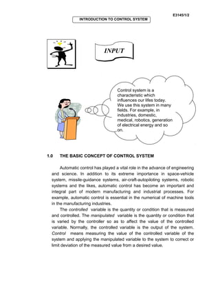
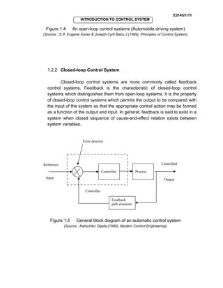
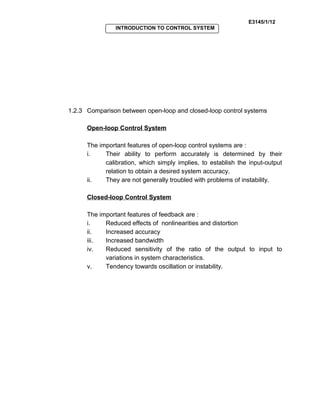
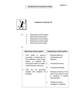
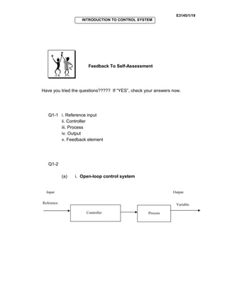

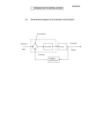

Control systems are used in many fields like industries, homes, and medical equipment. They are classified as open-loop or closed-loop systems. Open-loop systems operate independently of feedback, while closed-loop systems incorporate feedback to reduce errors between the actual and desired output. Examples of open-loop systems include washing machines and electric kettles, while closed-loop systems include automatic toasters and refrigerators. Block diagrams are used in control engineering to show the functions and signal flows between components.