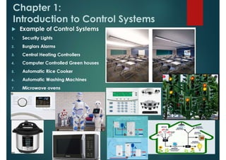
The document provides an introduction to control systems, including:
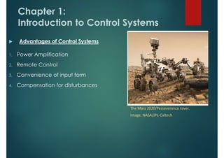
- Control systems are integral parts of modern society and are found in applications like rockets, manufacturing machines, and self-driving vehicles.
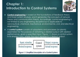
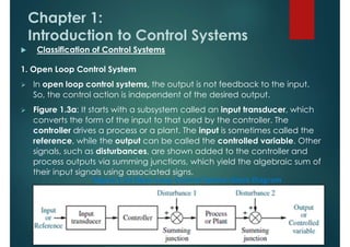
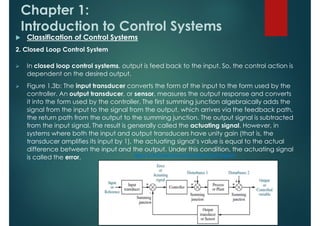
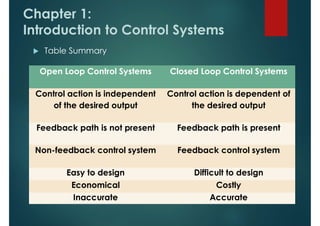
- The chapter defines a control system and describes their basic features and configurations, including open-loop and closed-loop systems.
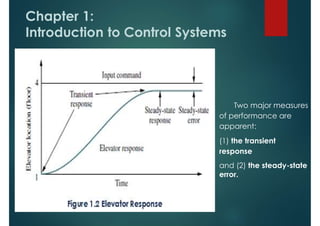
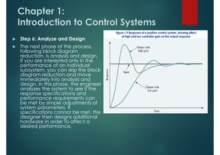
- The objectives of control system analysis and design are described as producing the desired transient response, reducing steady-state error, and achieving stability.
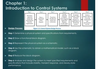
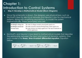
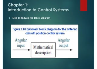
- The design process for control systems is outlined in six steps: determining requirements, drawing block diagrams, creating schematics, developing mathematical models, reducing block diagrams, and analyzing and designing the system.