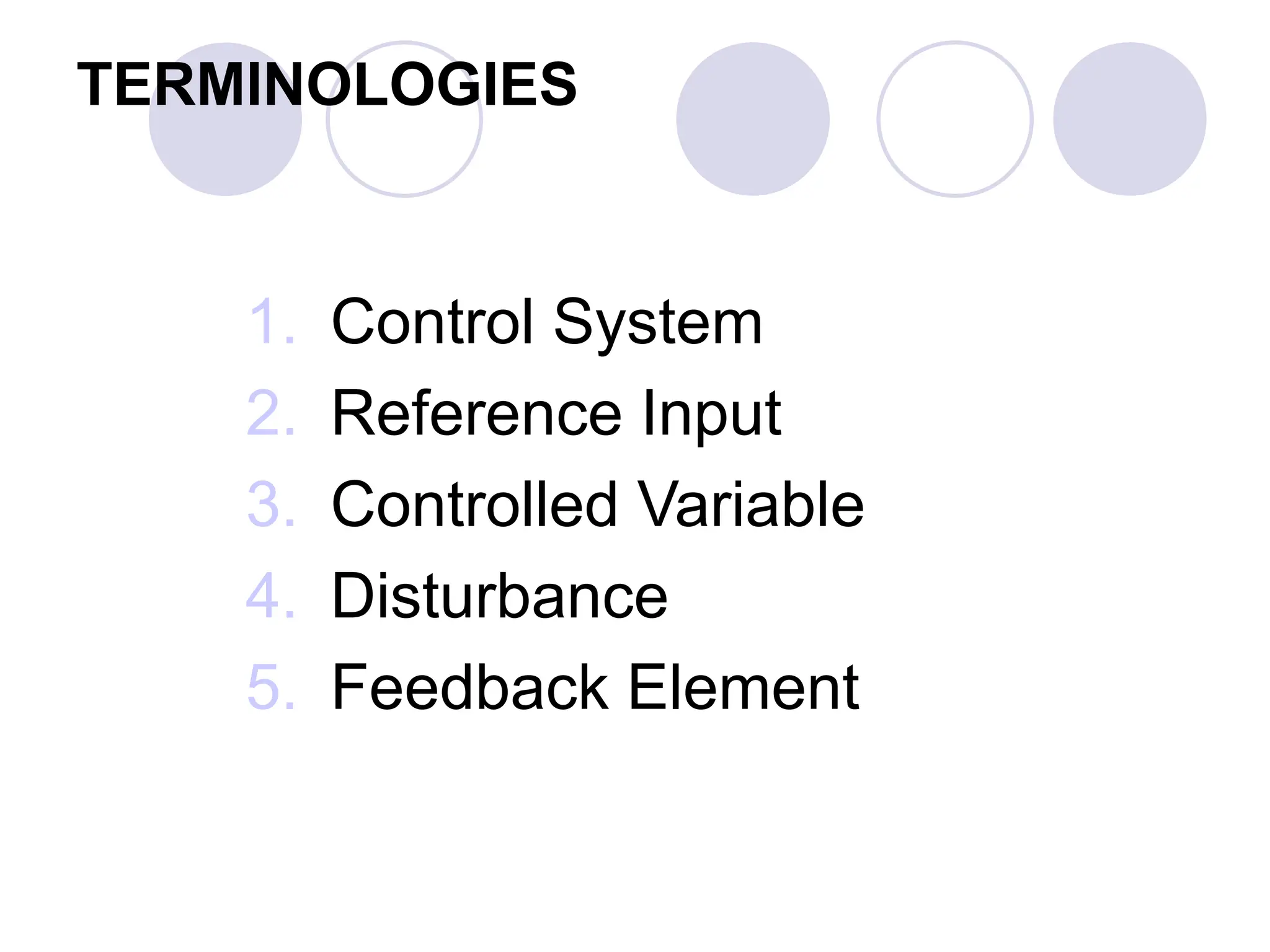
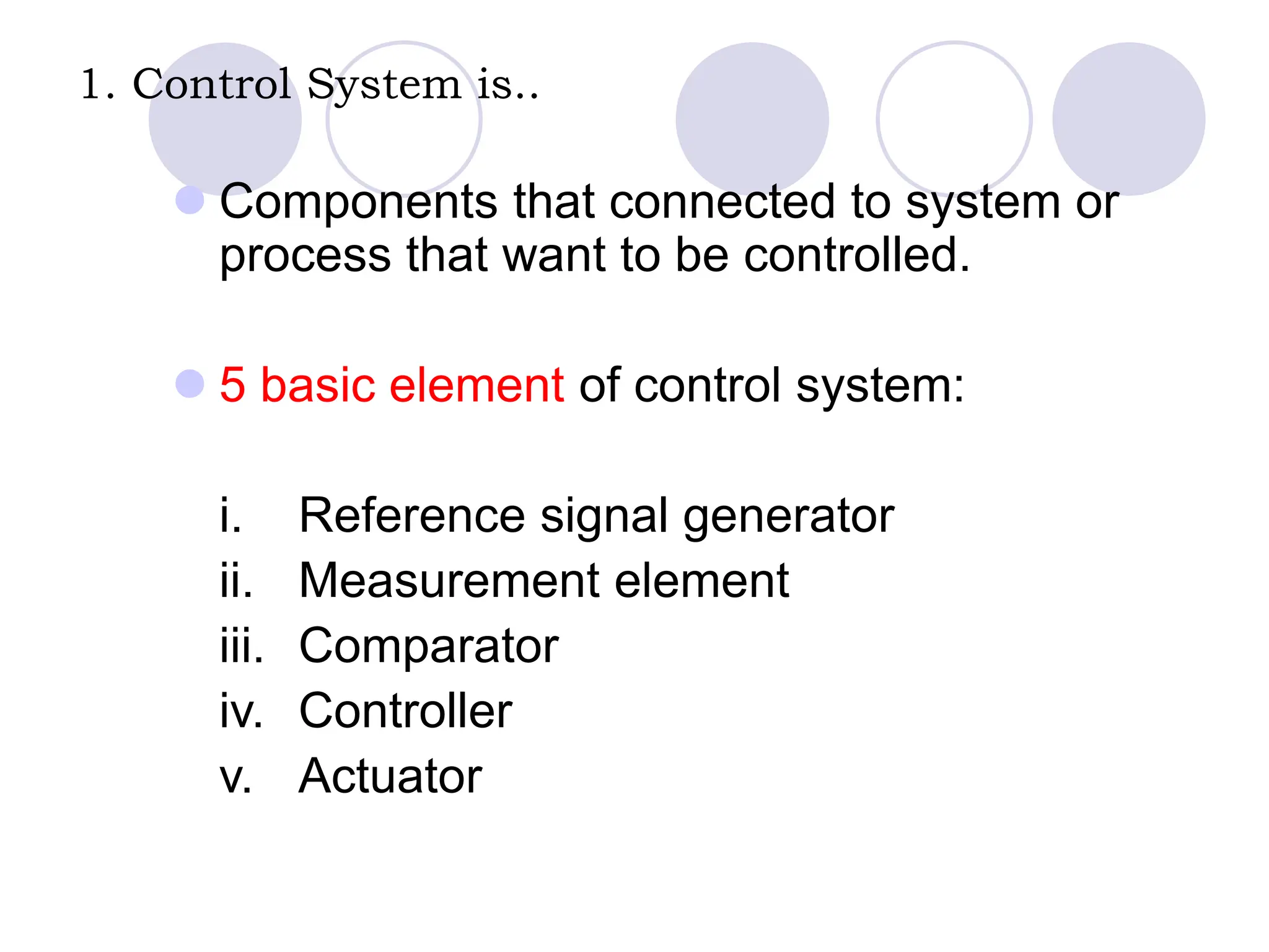
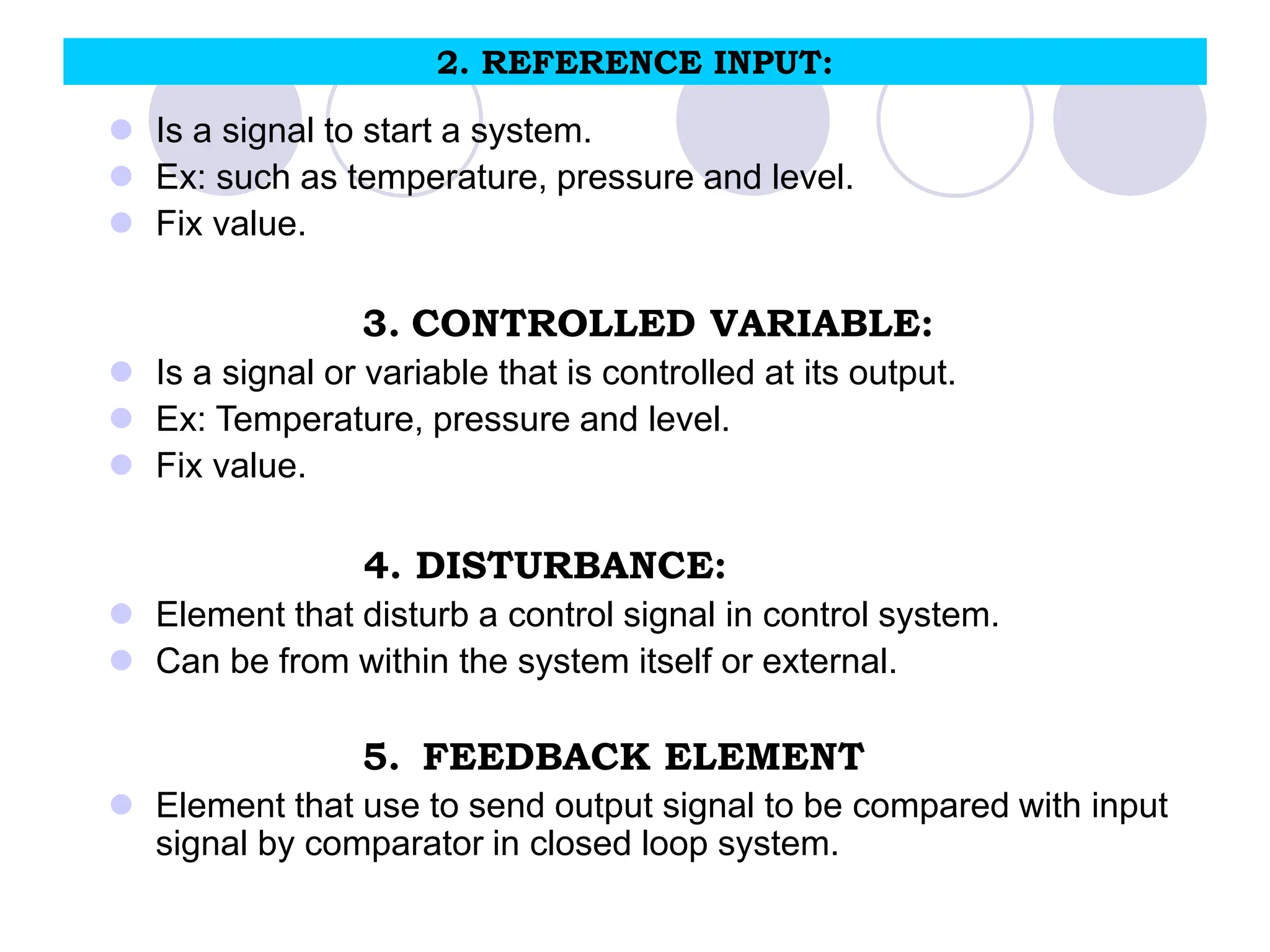
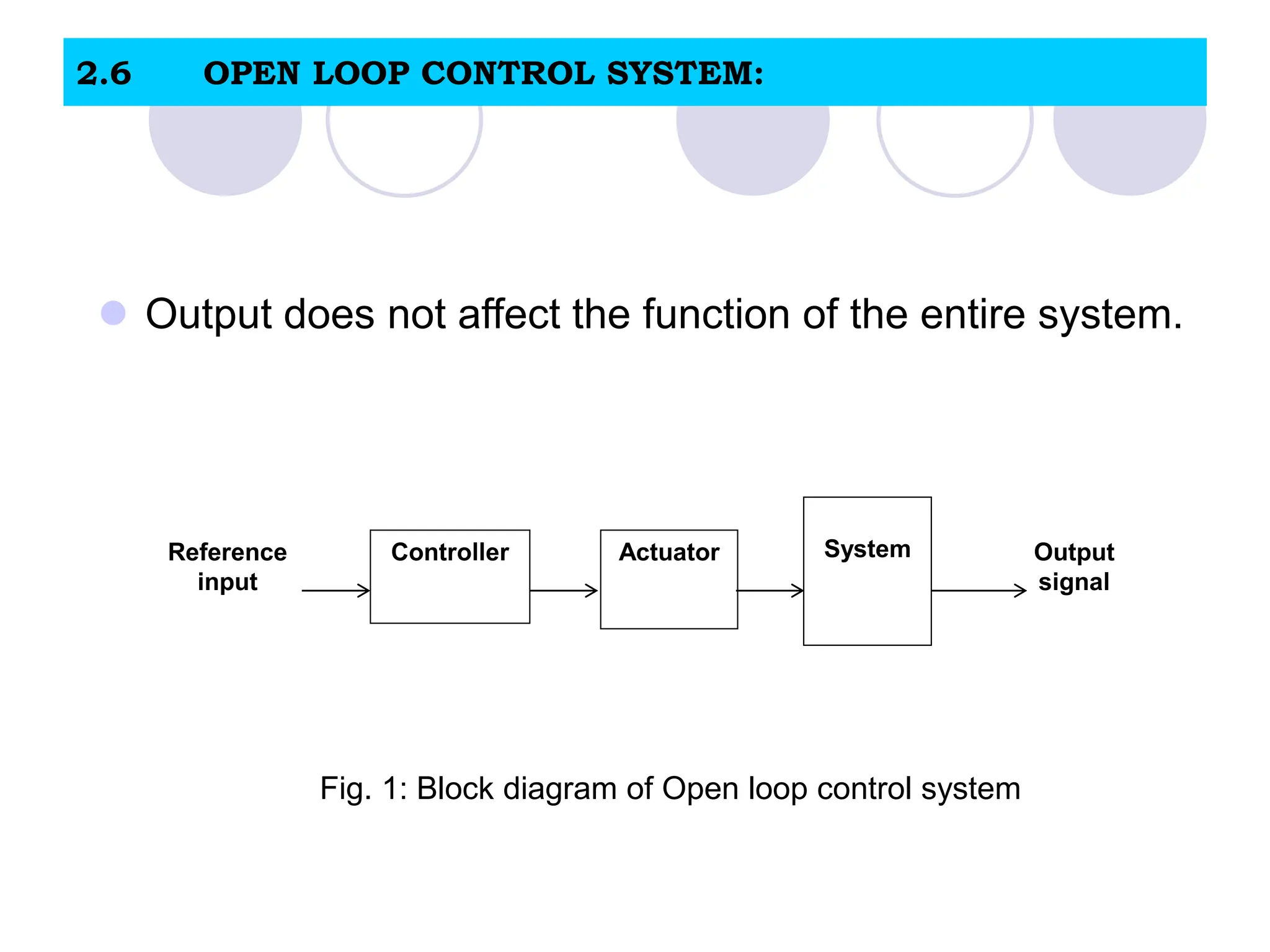
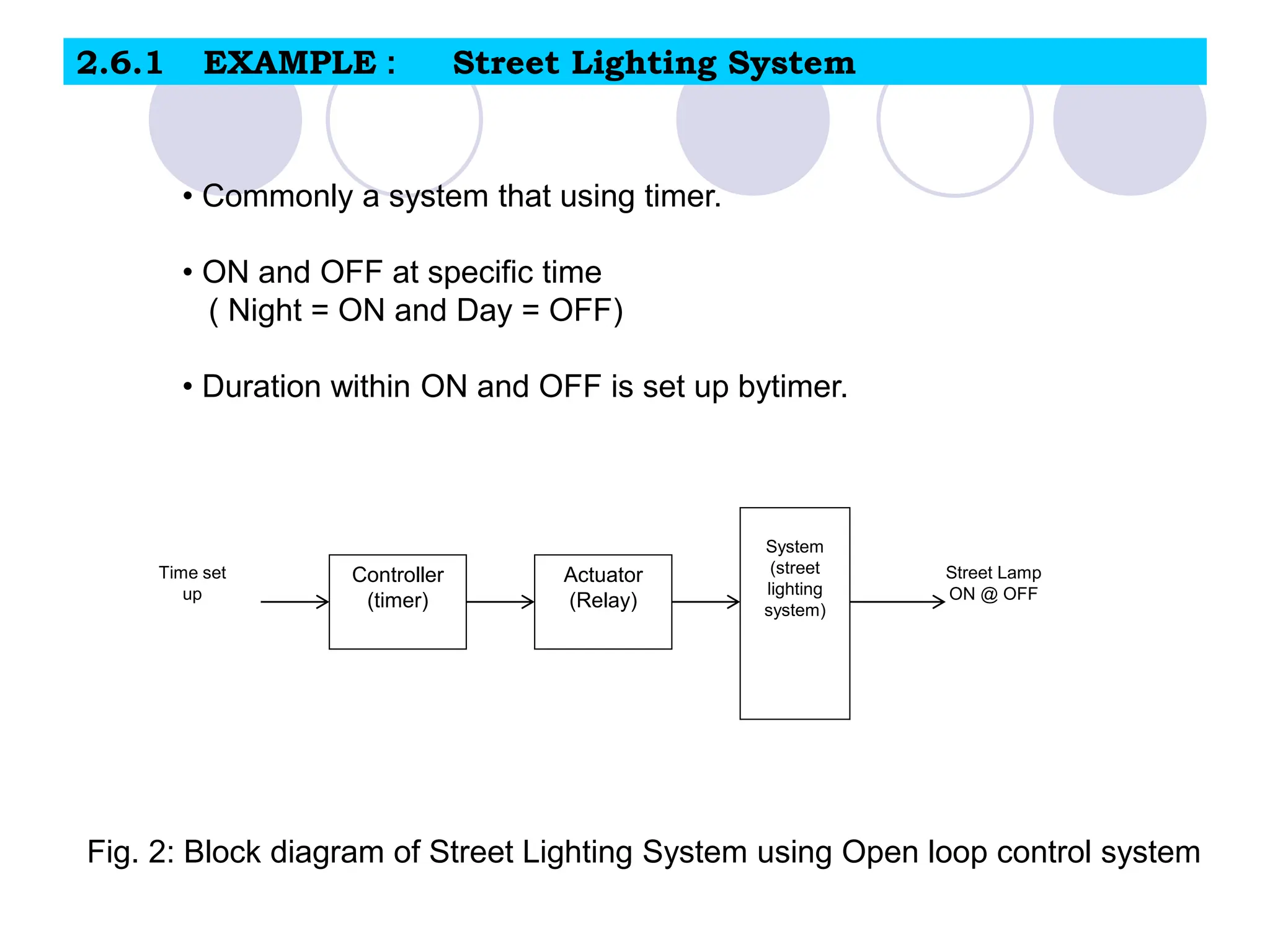
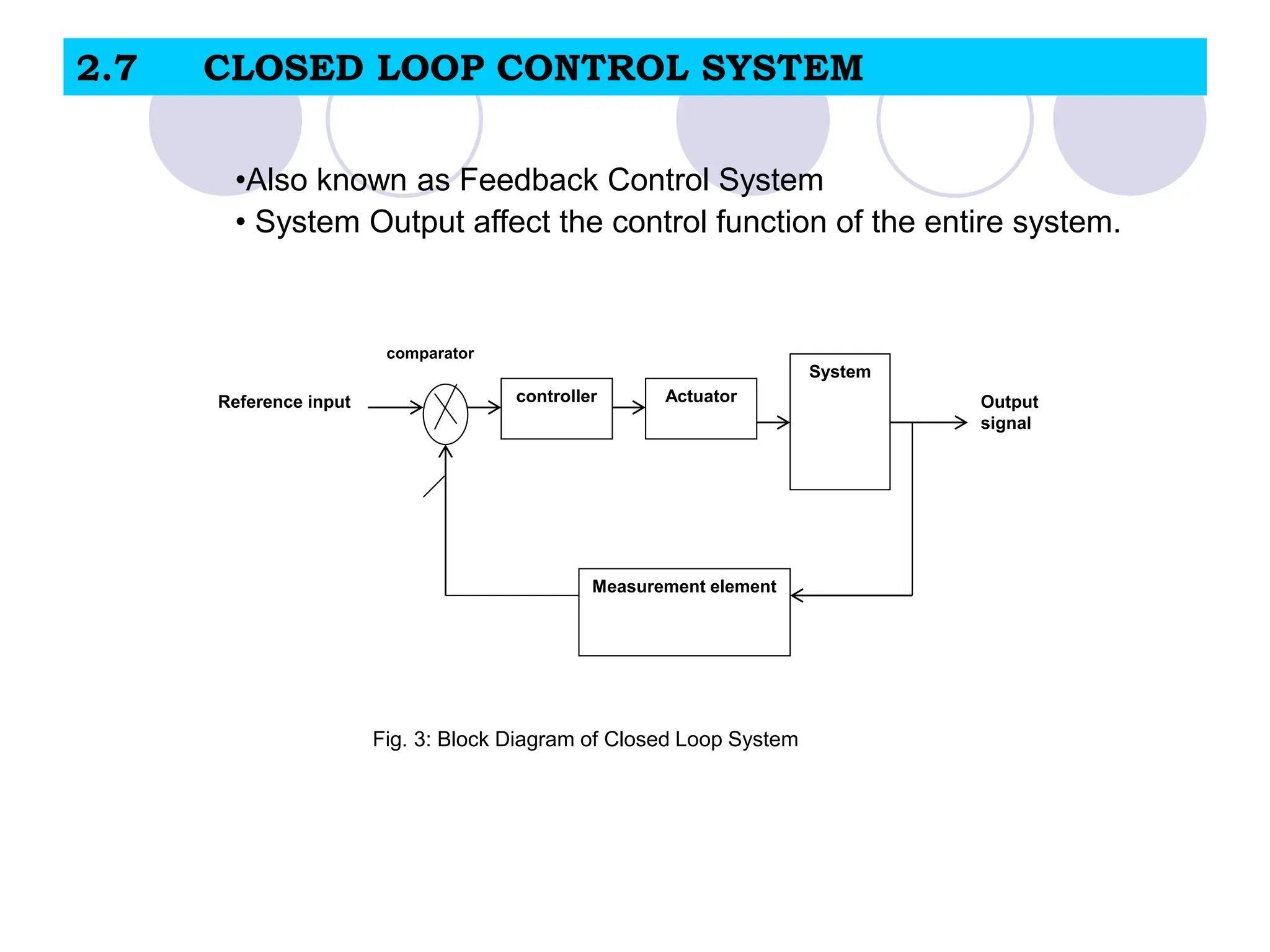
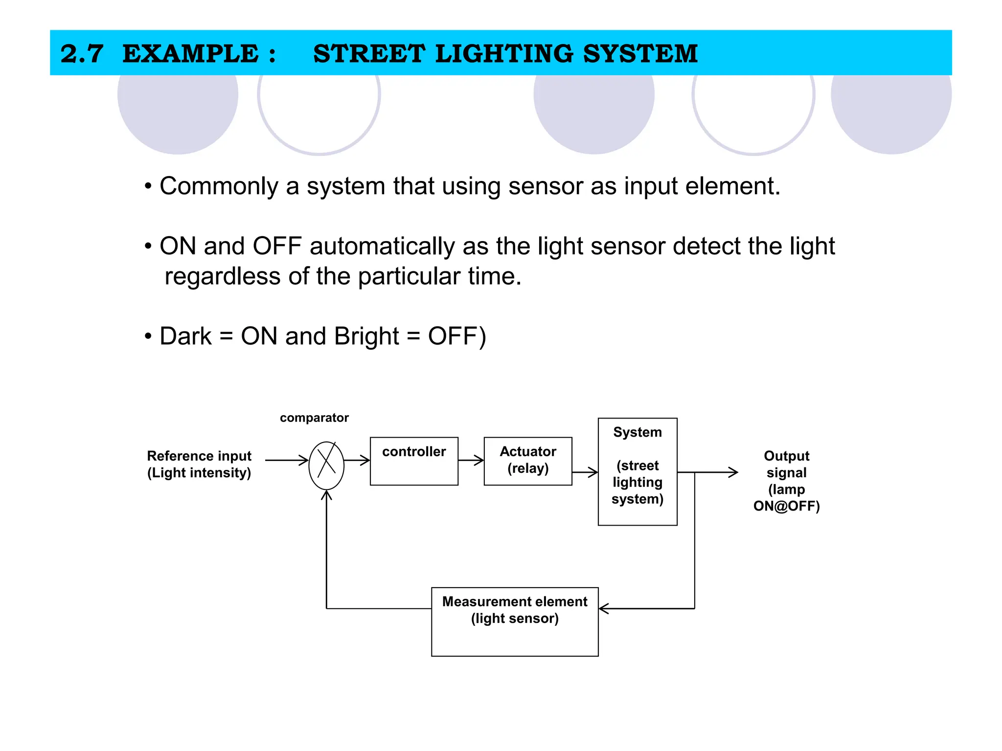
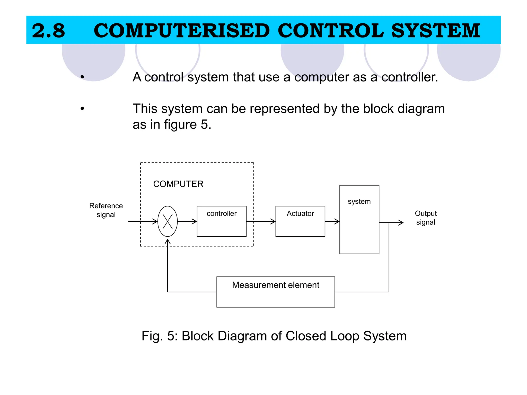
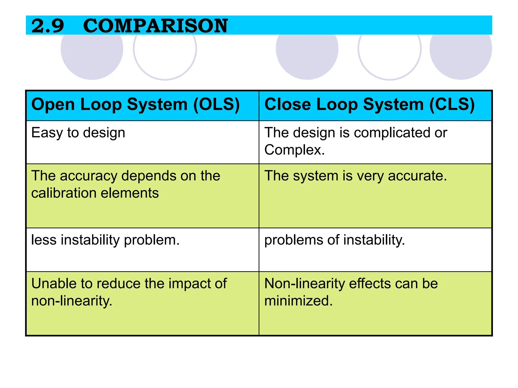
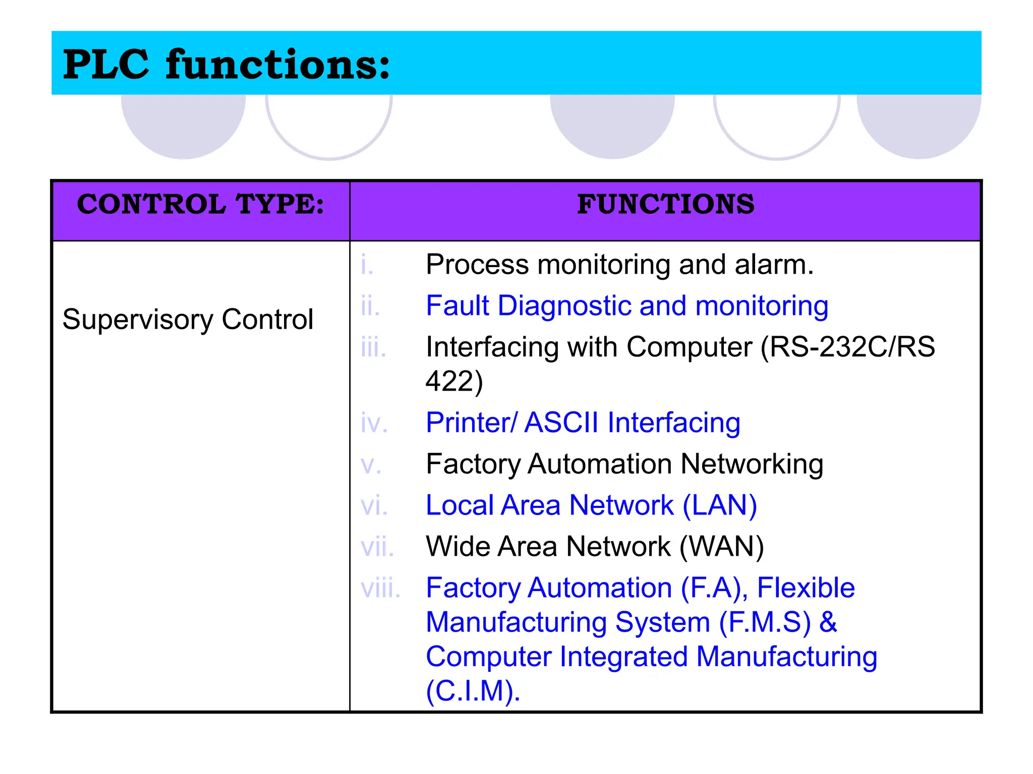
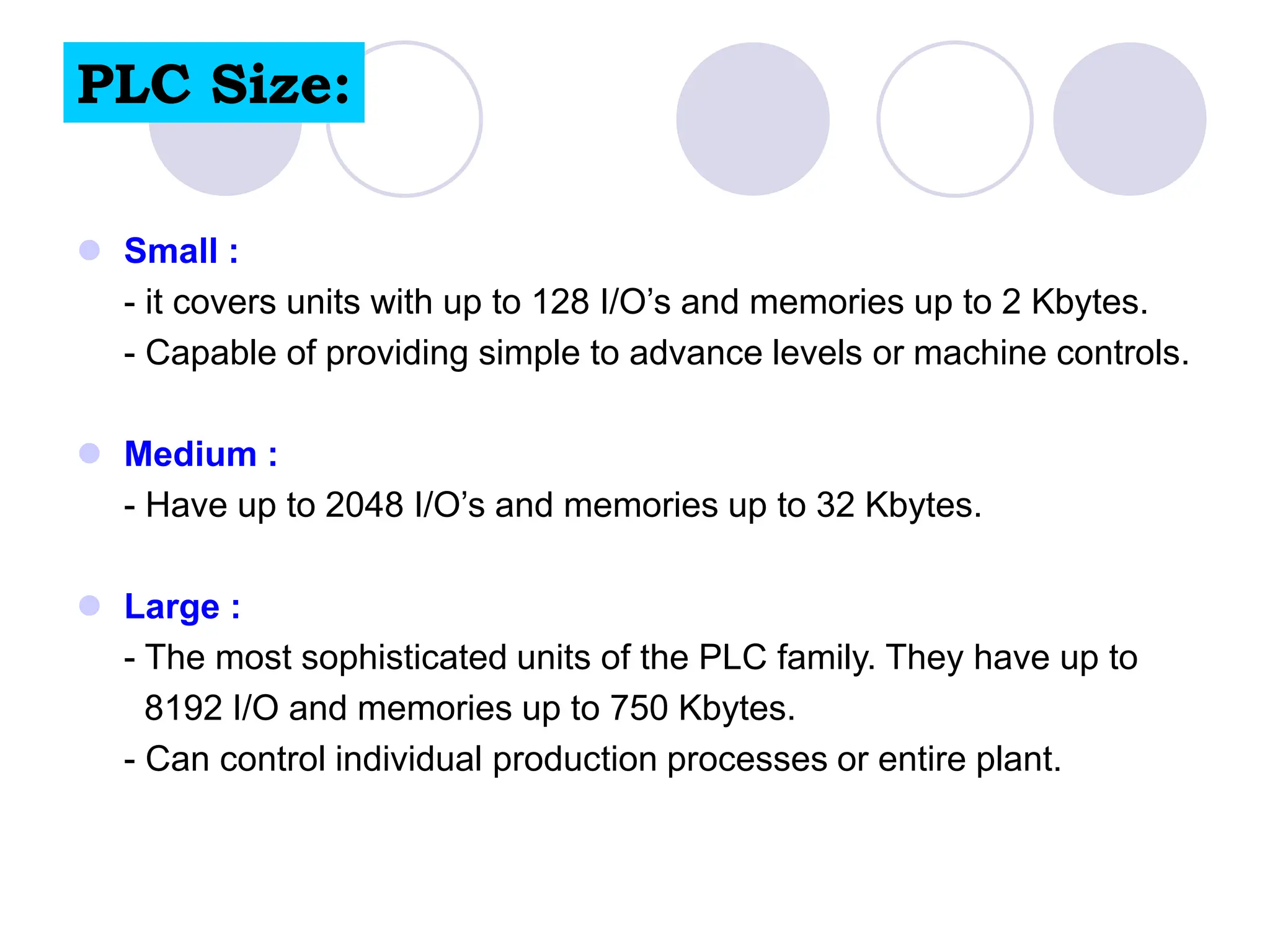
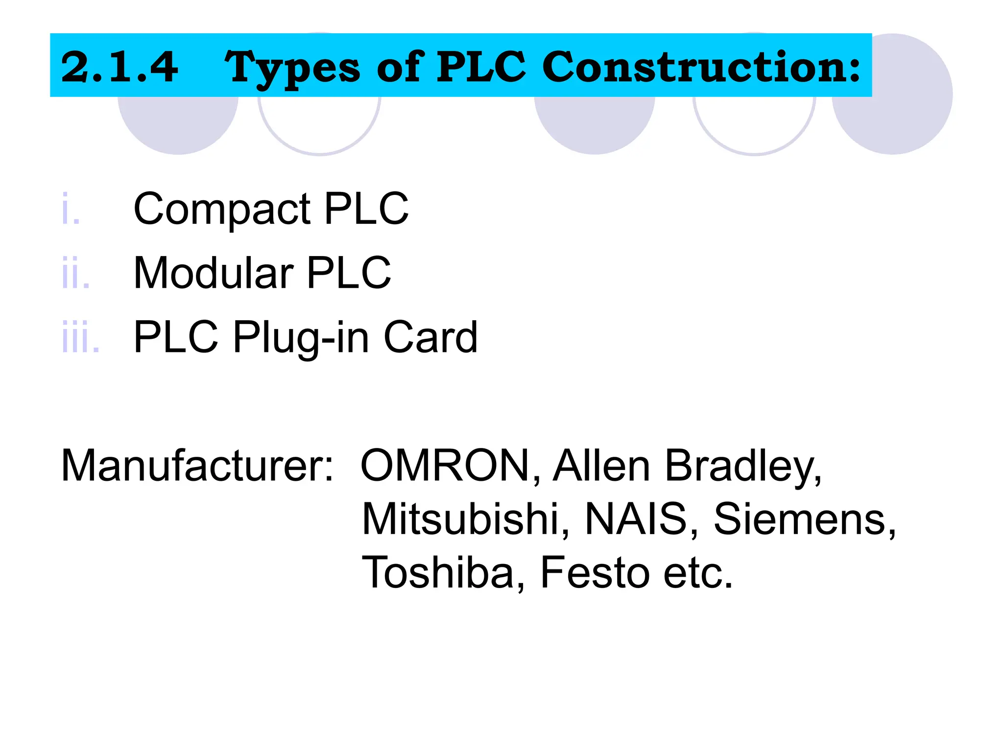
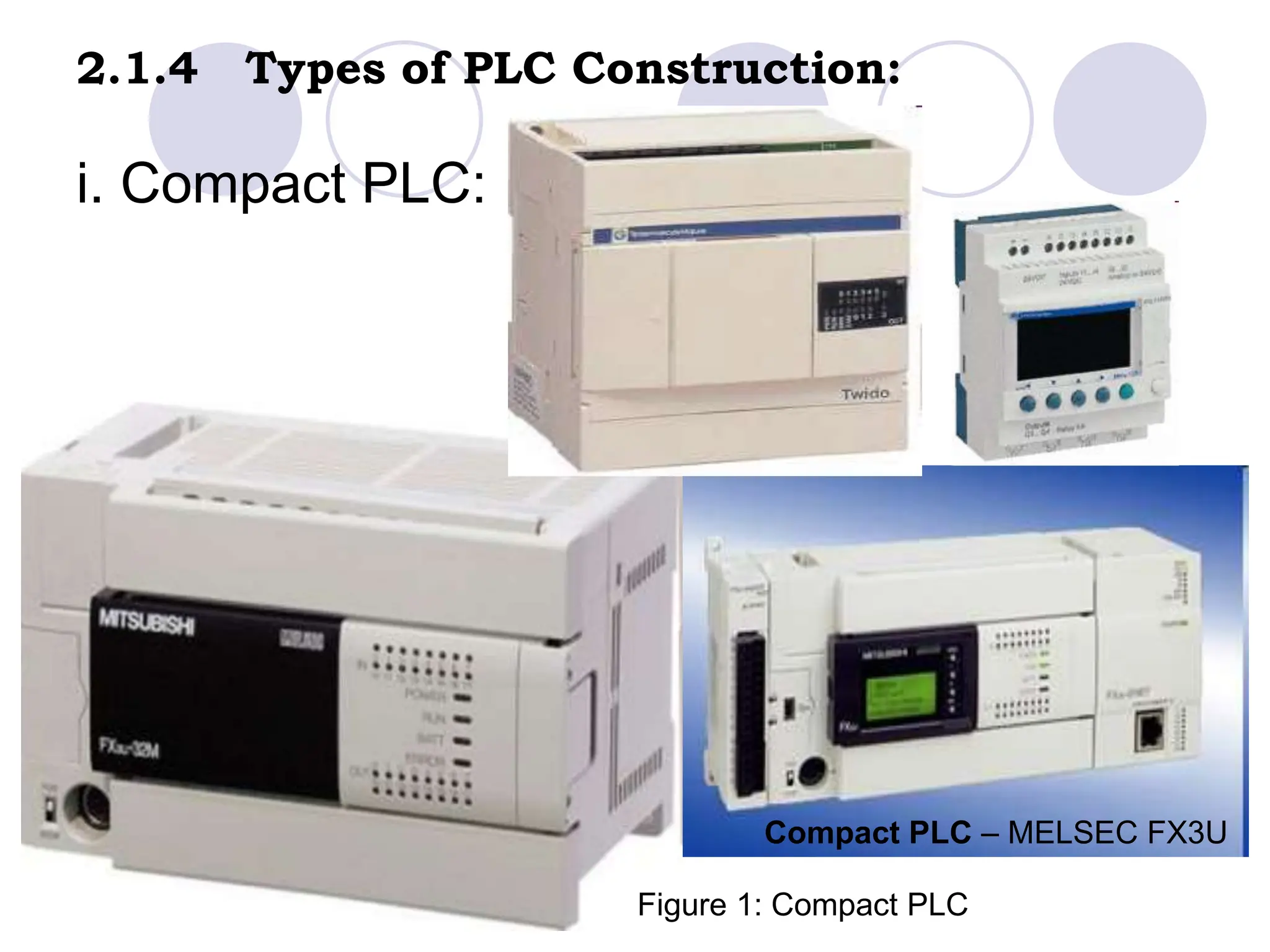
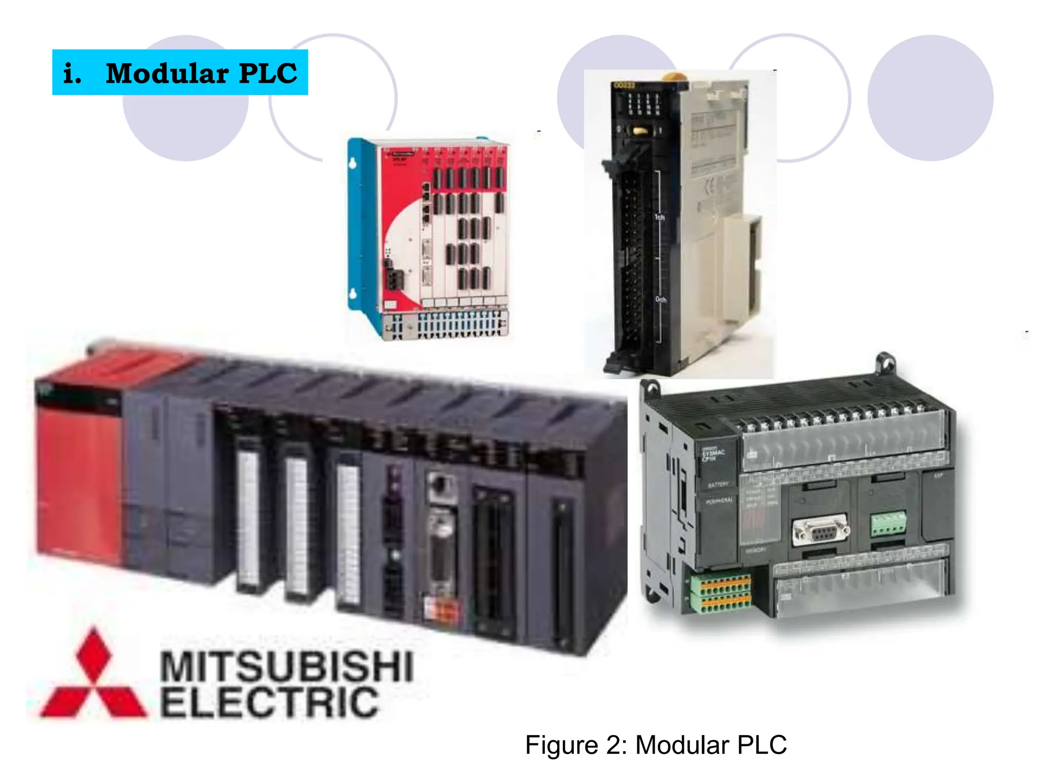
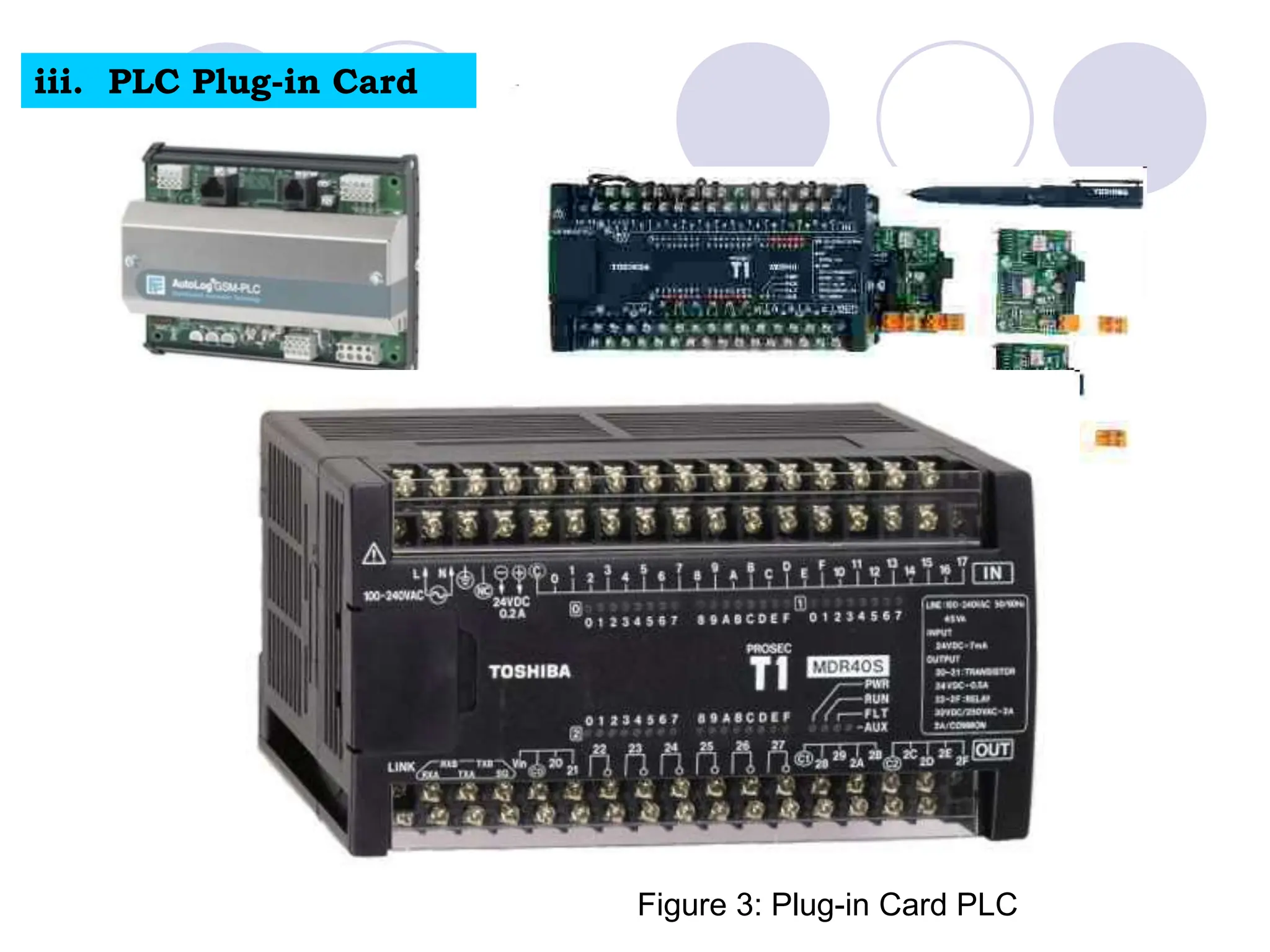
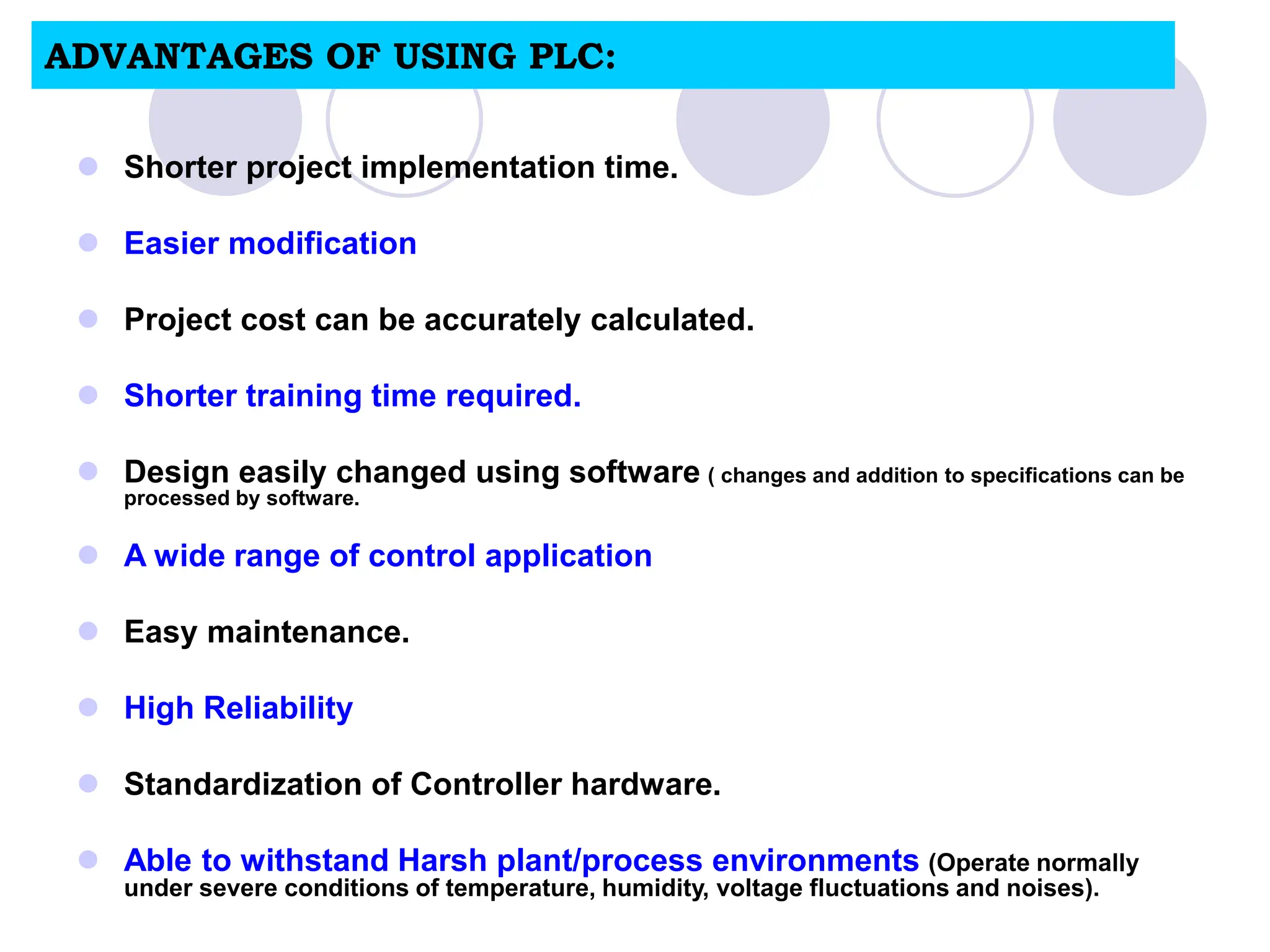
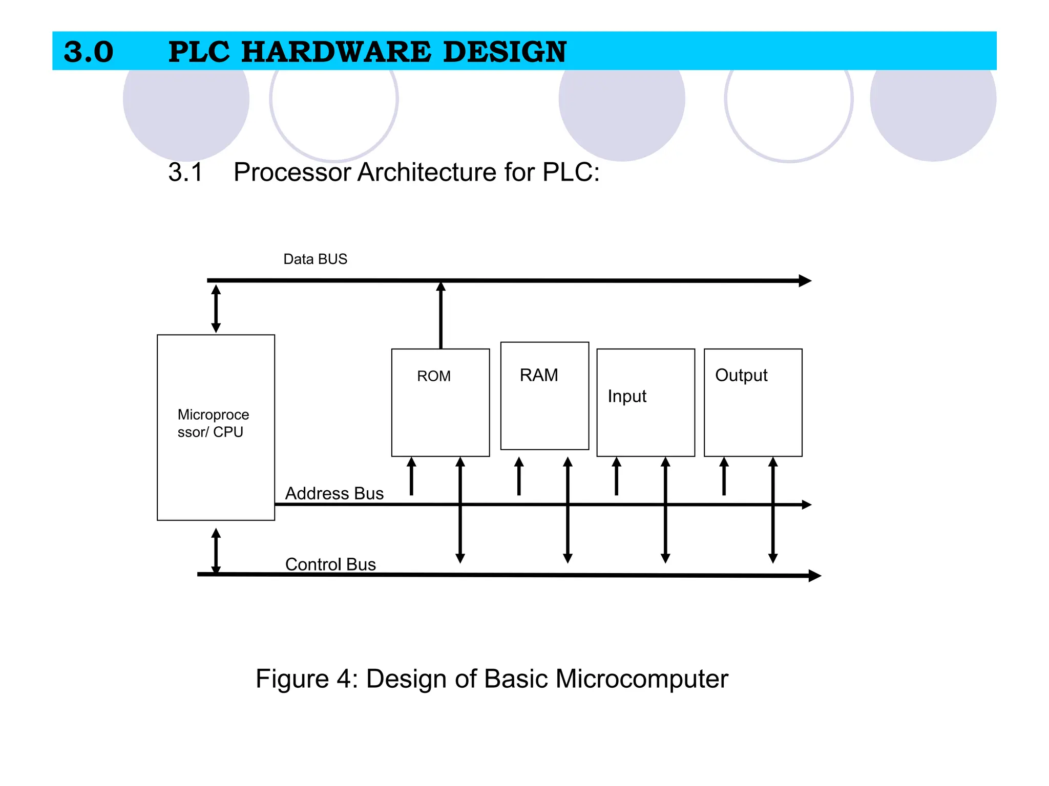
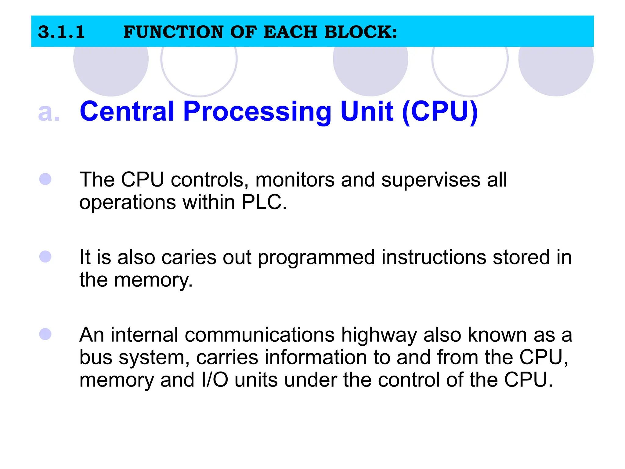
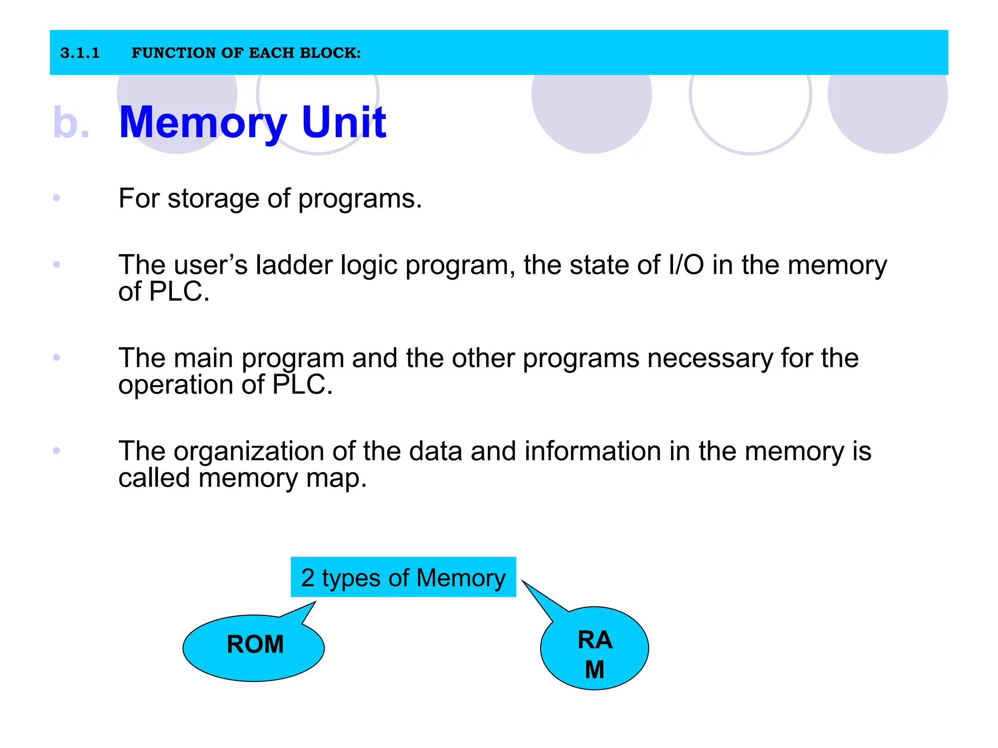
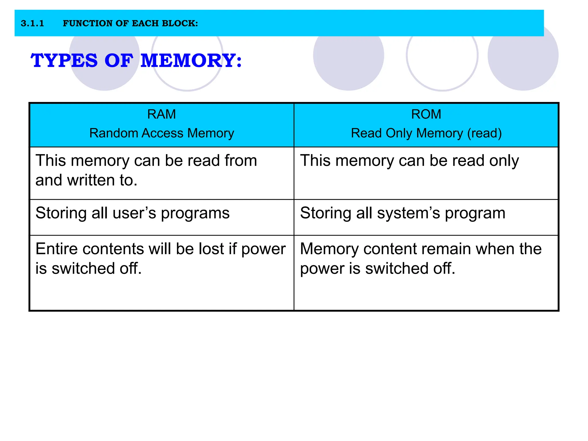
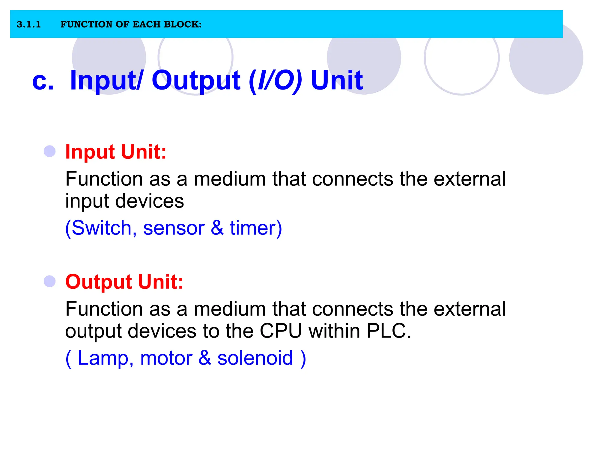
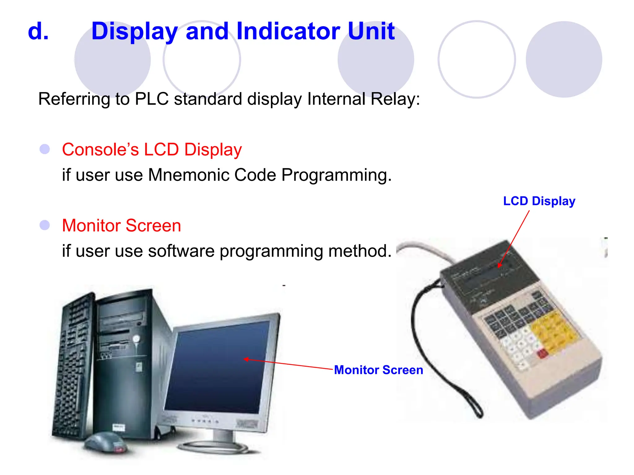
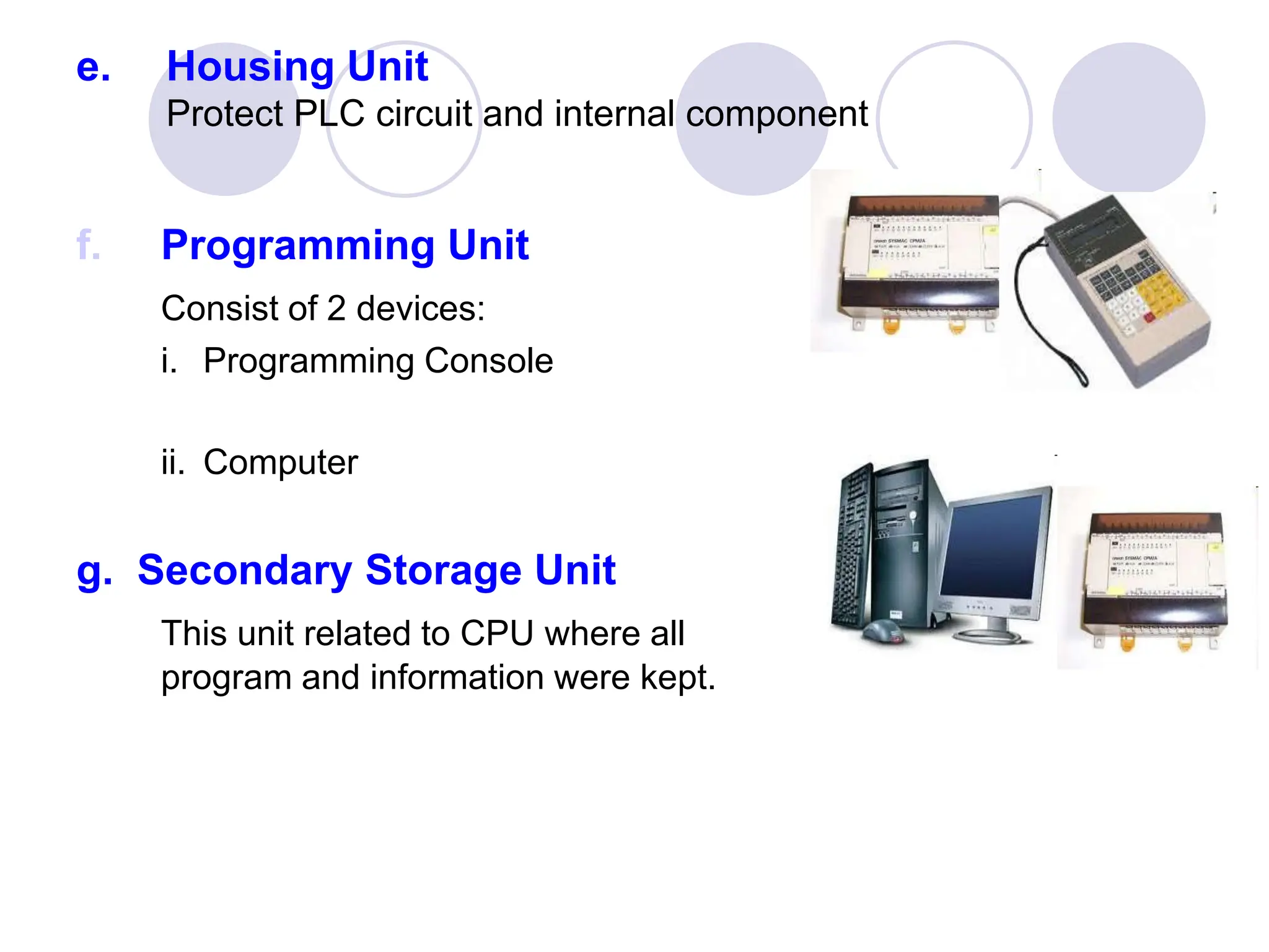
3. 1. Control System is..
Components that connected to system or
process that want to be controlled.
5 basic element of control system:
i. Reference signal generator
ii. Measurement element
iii. Comparator
iv. Controller
v. Actuator
4. 2. REFERENCE INPUT:
Is a signal to start a system.
Ex: such as temperature, pressure and level.
Fix value.
3. CONTROLLED VARIABLE:
Is a signal or variable that is controlled at its output.
Ex: Temperature, pressure and level.
Fix value.
4. DISTURBANCE:
Element that disturb a control signal in control system.
Can be from within the system itself or external.
5. FEEDBACK ELEMENT
Element that use to send output signal to be compared with input
signal by comparator in closed loop system.
5. 2.6 OPEN LOOP CONTROL SYSTEM:
Output does not affect the function of the entire system.
Controller Actuator System
Reference
input
Output
signal
Fig. 1: Block diagram of Open loop control system
6. 2.6.1 EXAMPLE : Street Lighting System
Controller
(timer)
Actuator
(Relay)
System
(street
lighting
system)
Time set
up
Street Lamp
ON @ OFF
Fig. 2: Block diagram of Street Lighting System using Open loop control system
• Commonly a system that using timer.
• ON and OFF at specific time
( Night = ON and Day = OFF)
• Duration within ON and OFF is set up bytimer.
7. 2.7 CLOSED LOOP CONTROL SYSTEM
Fig. 3: Block Diagram of Closed Loop System
Reference input controller Actuator
System
Measurement element
Output
signal
comparator
•Also known as Feedback Control System
• System Output affect the control function of the entire system.
8. 2.7 EXAMPLE : STREET LIGHTING SYSTEM
Reference input
(Light intensity)
controller Actuator
(relay)
System
(street
lighting
system)
Measurement element
(light sensor)
Output
signal
(lamp
ON@OFF)
comparator
• Commonly a system that using sensor as input element.
• ON and OFF automatically as the light sensor detect the light
regardless of the particular time.
• Dark = ON and Bright = OFF)
9. 2.8 COMPUTERISED CONTROL SYSTEM
Reference
signal controller Actuator
system
Output
signal
COMPUTER
Measurement element
Fig. 5: Block Diagram of Closed Loop System
• A control system that use a computer as a controller.
• This system can be represented by the block diagram
as in figure 5.
10. 2.9 COMPARISON
Open Loop System (OLS) Close Loop System (CLS)
Easy to design The design is complicated or
Complex.
The accuracy depends on the
calibration elements
The system is very accurate.
less instability problem. problems of instability.
Unable to reduce the impact of
non-linearity.
Non-linearity effects can be
minimized.
11. INTRODUCTION TO PLC
2. Explain PLC
2.1.1 Define PLC terminologies
2.1.2 Explain PLC background
2.1.3 Explain PLC functions
2.1.4 List and explain the types and advantages
of PLC.
12. 2.1.1Define PLC
What is Programmable Logic Controller (PLC) ?
Definition: National Electrical Manufacturers Association
US (NEMA)
A PLC is a digital operating electronic apparatus
which uses a programmable memory for internal
storage of instruction for implementing specific
function such as logic, sequencing, timing, counting
and arithmetic to control through analog or digital
input/output modules various types of machines or
process.
13. Define PLC terminologies:
Several different terms used to described
programmable controllers:
i. PLC –Programmable Logic Controller (UK origin)
ii. PC – Programmable controller (US origin)
Most referring to the functional operation of the
machine.
PLC has been used in this text to avoid confusion
with the personal computer.
14. 2.1.2 Explain PLC background
PLC Development factors:
i. needs for low-cost
ii. Flexible
iii. Easily commissioned/ smart usage
15. Historical Background:
In 1968, a group of engineers from General
Motors developed the concept of PLC with an
initial specification. The PLC must be:
i. Easy to program.
ii. Not need rewiring the control system if
change the program.
iii. Smaller in size, cheaper and high reliability.
iv. simple construction and low maintenance
v. Cost- competitive
16. 2.1.3 PLC functions
CONTROL TYPE: FUNCTIONS
Sequence Control
i. Conventional Relay Control Logic
replacer
ii. Timers/ Counter
iii. PCB Card controller replacer
iv. Auto/Semi-auto/Manual control of
machine and process.
Advanced/
Sophisticated Control
i. Arithmetic operation (+, -, × , ÷)
ii. Information Handling
iii. Analog Control (Temperature, Pressure )
iv. P.I.D (Proportional Integral Derivation)
v. Servo Motor Control
vi. Stepper Motor control
17. PLC functions:
CONTROL TYPE: FUNCTIONS
Supervisory Control
i. Process monitoring and alarm.
ii. Fault Diagnostic and monitoring
iii. Interfacing with Computer (RS-232C/RS
422)
iv. Printer/ ASCII Interfacing
v. Factory Automation Networking
vi. Local Area Network (LAN)
vii. Wide Area Network (WAN)
viii. Factory Automation (F.A), Flexible
Manufacturing System (F.M.S) &
Computer Integrated Manufacturing
(C.I.M).
18. Small :
- it covers units with up to 128 I/O’s and memories up to 2 Kbytes.
- Capable of providing simple to advance levels or machine controls.
Medium :
- Have up to 2048 I/O’s and memories up to 32 Kbytes.
Large :
- The most sophisticated units of the PLC family. They have up to
8192 I/O and memories up to 750 Kbytes.
- Can control individual production processes or entire plant.
PLC Size:
19. i. Compact PLC
ii. Modular PLC
iii. PLC Plug-in Card
Manufacturer: OMRON, Allen Bradley,
Mitsubishi, NAIS, Siemens,
Toshiba, Festo etc.
2.1.4 Types of PLC Construction:
20. 2.1.4 Types of PLC Construction:
i. Compact PLC:
Compact PLC – MELSEC FX3U
Figure 1: Compact PLC
23. ADVANTAGES OF USING PLC:
Shorter project implementation time.
Easier modification
Project cost can be accurately calculated.
Shorter training time required.
Design easily changed using software ( changes and addition to specifications can be
processed by software.
A wide range of control application
Easy maintenance.
High Reliability
Standardization of Controller hardware.
Able to withstand Harsh plant/process environments (Operate normally
under severe conditions of temperature, humidity, voltage fluctuations and noises).
25. 3.0 PLC HARDWARE DESIGN
Microproce
ssor/ CPU
ROM RAM
Input
Output
Data BUS
Control Bus
Address Bus
3.1 Processor Architecture for PLC:
Figure 4: Design of Basic Microcomputer
26. 3.1.1 FUNCTION OF EACH BLOCK:
a. Central Processing Unit (CPU)
The CPU controls, monitors and supervises all
operations within PLC.
It is also caries out programmed instructions stored in
the memory.
An internal communications highway also known as a
bus system, carries information to and from the CPU,
memory and I/O units under the control of the CPU.
27. 3.1.1 FUNCTION OF EACH BLOCK:
b. Memory Unit
• For storage of programs.
• The user’s ladder logic program, the state of I/O in the memory
of PLC.
• The main program and the other programs necessary for the
operation of PLC.
• The organization of the data and information in the memory is
called memory map.
2 types of Memory
RA
M
ROM
28. TYPES OF MEMORY:
RAM
Random Access Memory
ROM
Read Only Memory (read)
This memory can be read from
and written to.
This memory can be read only
Storing all user’s programs Storing all system’s program
Entire contents will be lost if power
is switched off.
Memory content remain when the
power is switched off.
3.1.1 FUNCTION OF EACH BLOCK:
29. c. Input/ Output (I/O) Unit
Input Unit:
Function as a medium that connects the external
input devices
(Switch, sensor & timer)
Output Unit:
Function as a medium that connects the external
output devices to the CPU within PLC.
( Lamp, motor & solenoid )
3.1.1 FUNCTION OF EACH BLOCK:
32. d. Display and Indicator Unit
Referring to PLC standard display Internal Relay:
Console’s LCD Display
if user use Mnemonic Code Programming.
Monitor Screen
if user use software programming method.
LCD Display
Monitor Screen
33. e. Housing Unit
Protect PLC circuit and internal component
f. Programming Unit
Consist of 2 devices:
i. Programming Console
ii. Computer
g. Secondary Storage Unit
This unit related to CPU where all
program and information were kept.
34. h. Power Supply Unit:
Supplies DC power to the Central Processing Unit, Input Unit and
Output Unit.
i. Printing Unit
Used to print control system programming that controlled by PLC
wether graphically or text.