Downloaded 50 times


1) The document discusses the principles of shielded gas arc welding, specifically TIG and MIG welding. It aims to explain the techniques, equipment, and advantages/disadvantages of each process. 2) TIG welding uses a non-consumable tungsten electrode within an inert gas shield to produce an arc for welding. MIG welding uses a consumable wire electrode and an inert gas shield. 3) The document covers TIG welding equipment, joint preparation, power sources, torch design, and electrode selection. It also briefly discusses MIG welding.
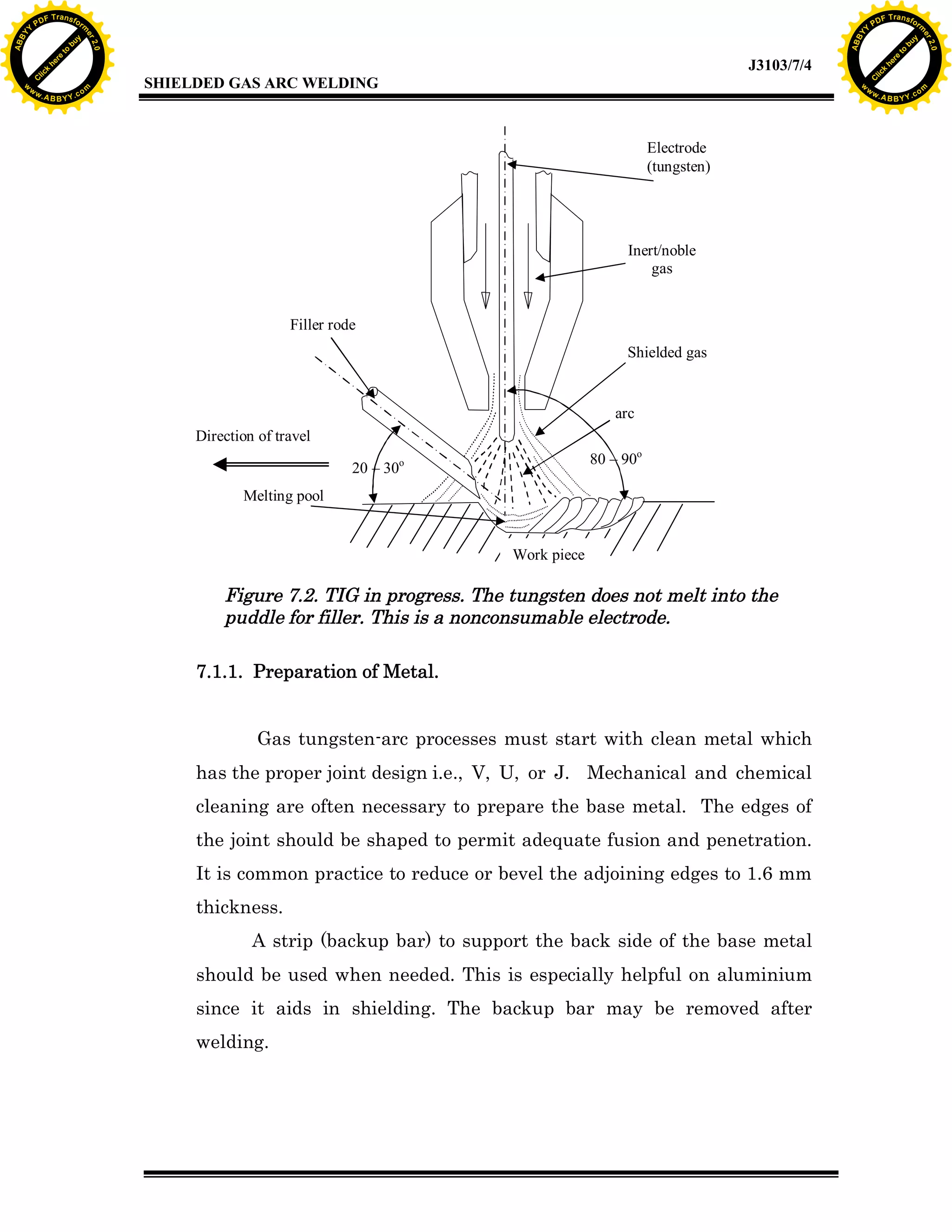
Overview of objectives for learning about TIG and MIG welding, including principles and techniques.
Describes the importance of creating a weld without contamination, using inert gases for shielding.
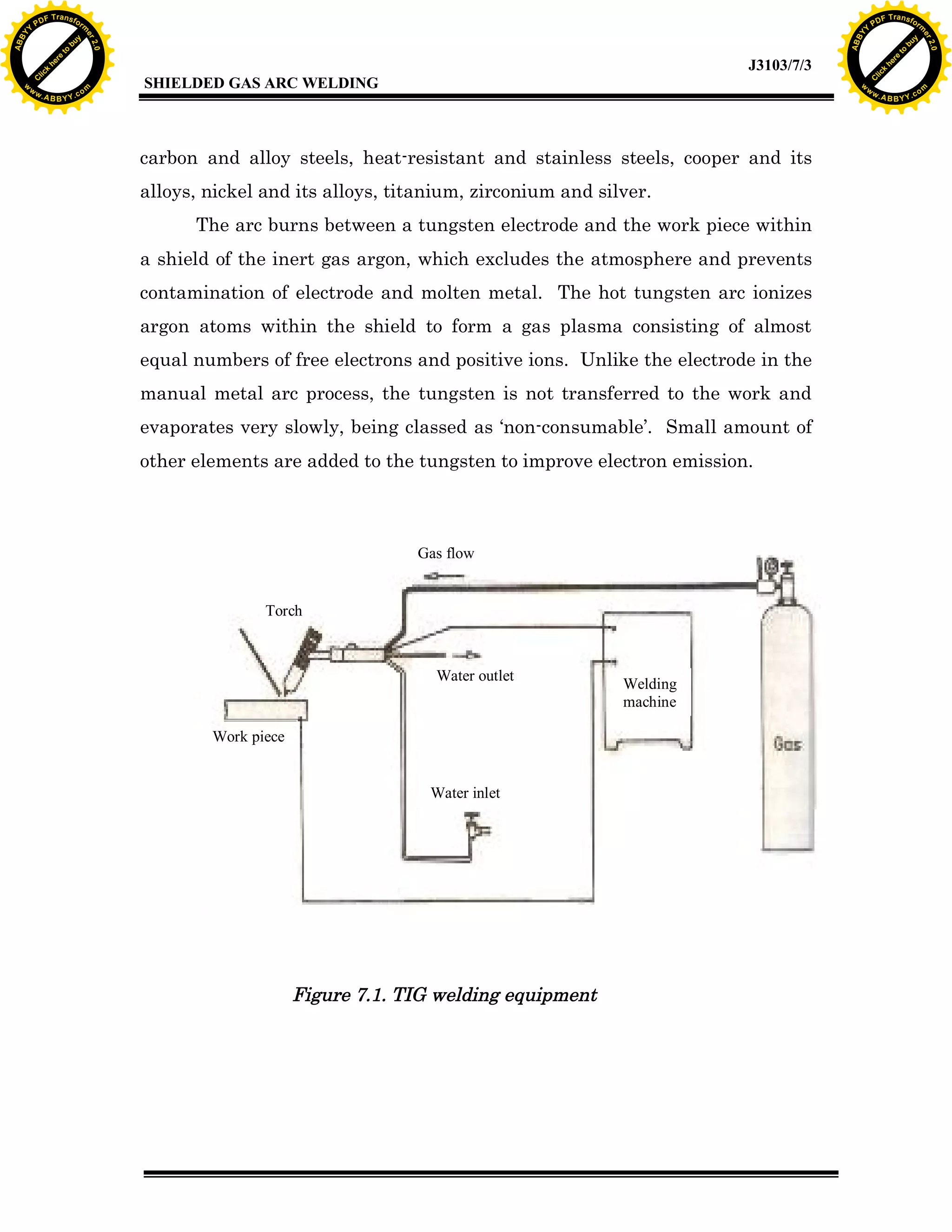
Explains the setup of TIG welding, including the types of machines, joint preparation, and welding procedures.
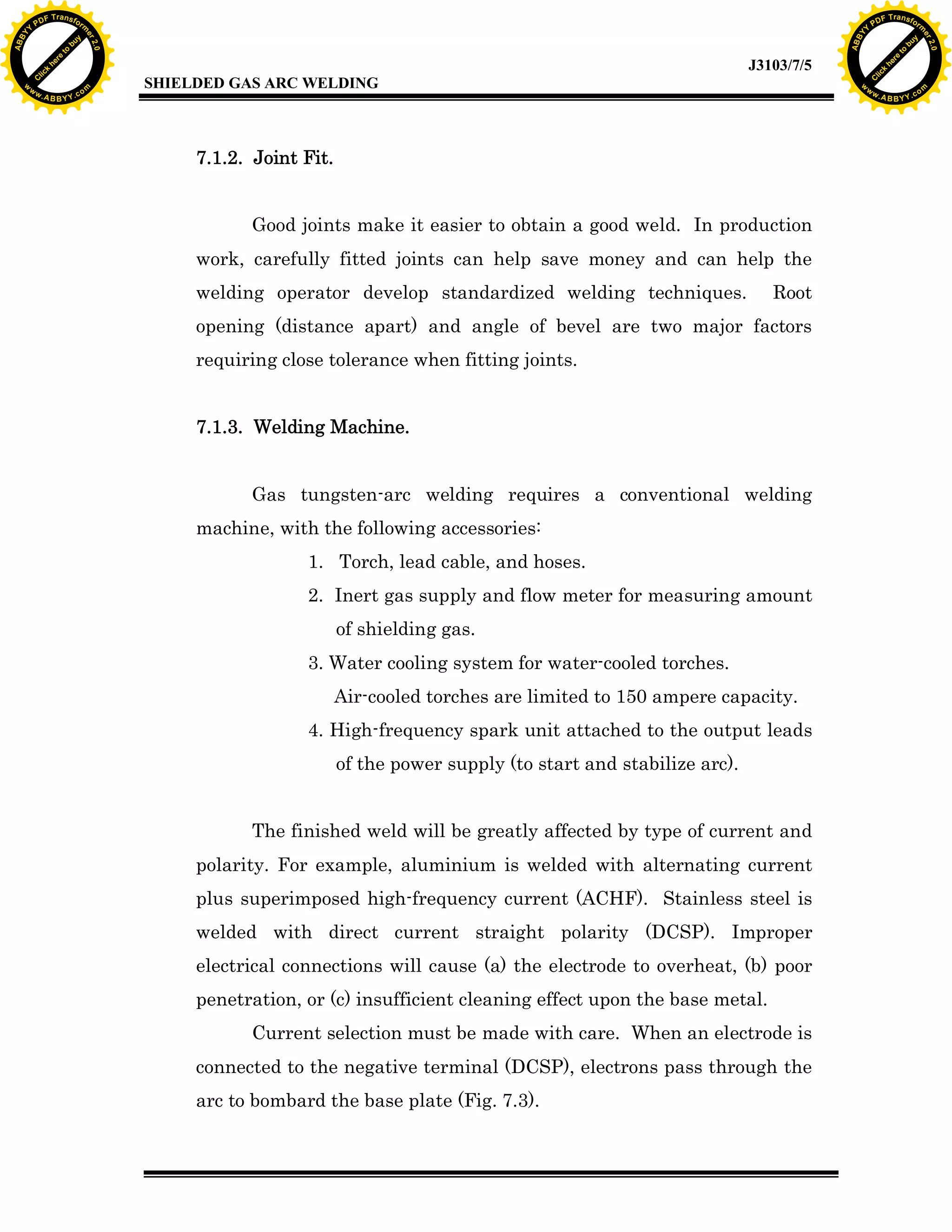
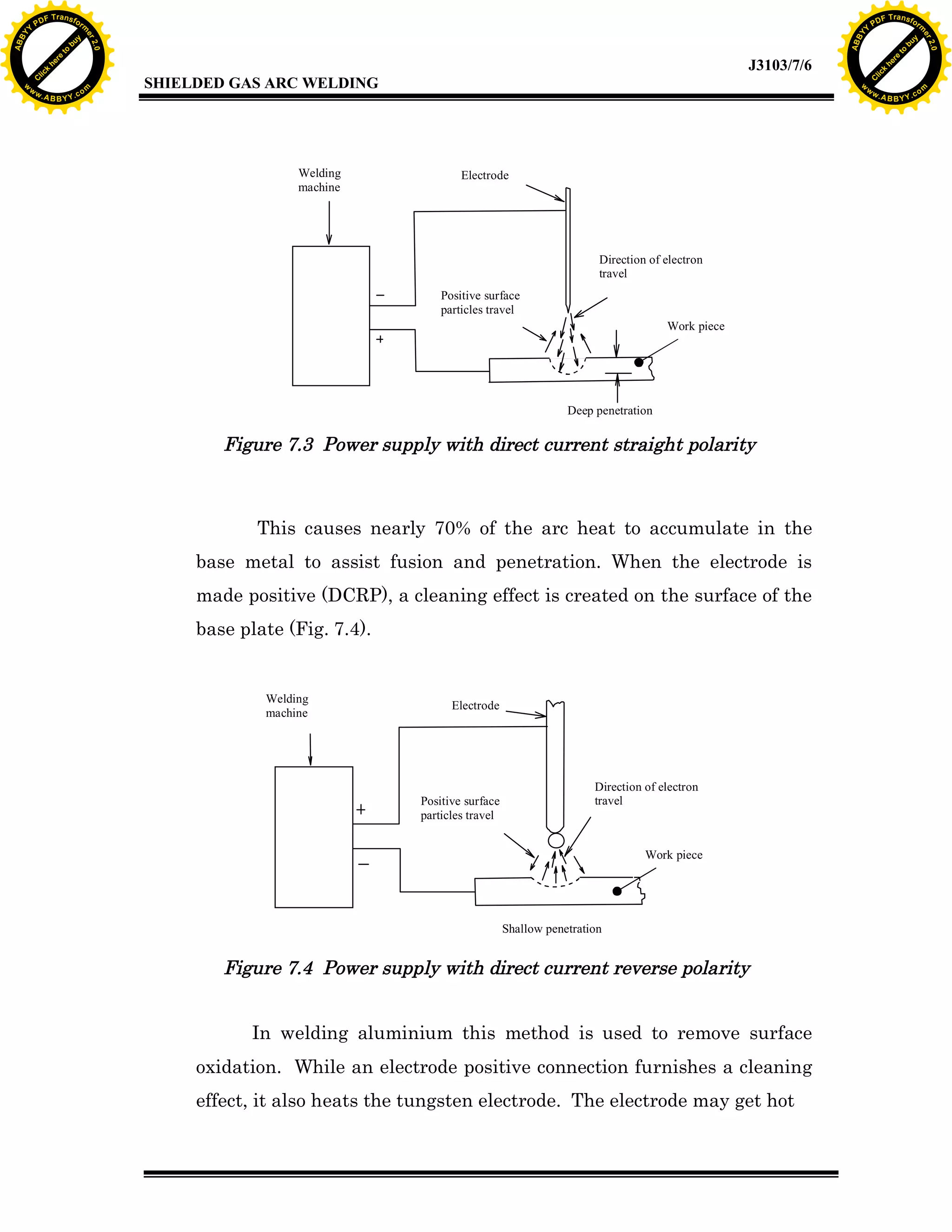
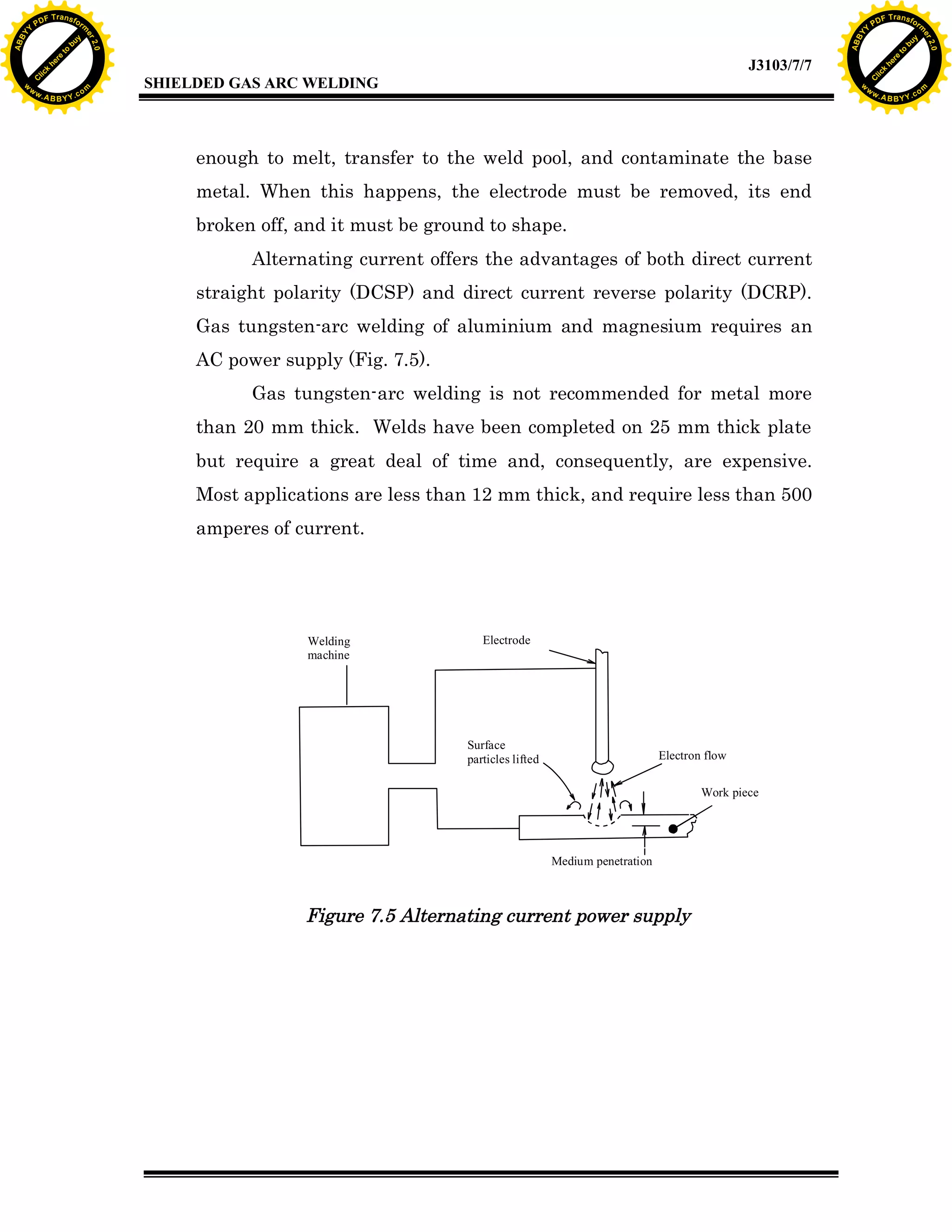
Details the effects of direct current and alternating current on different metals in TIG welding.
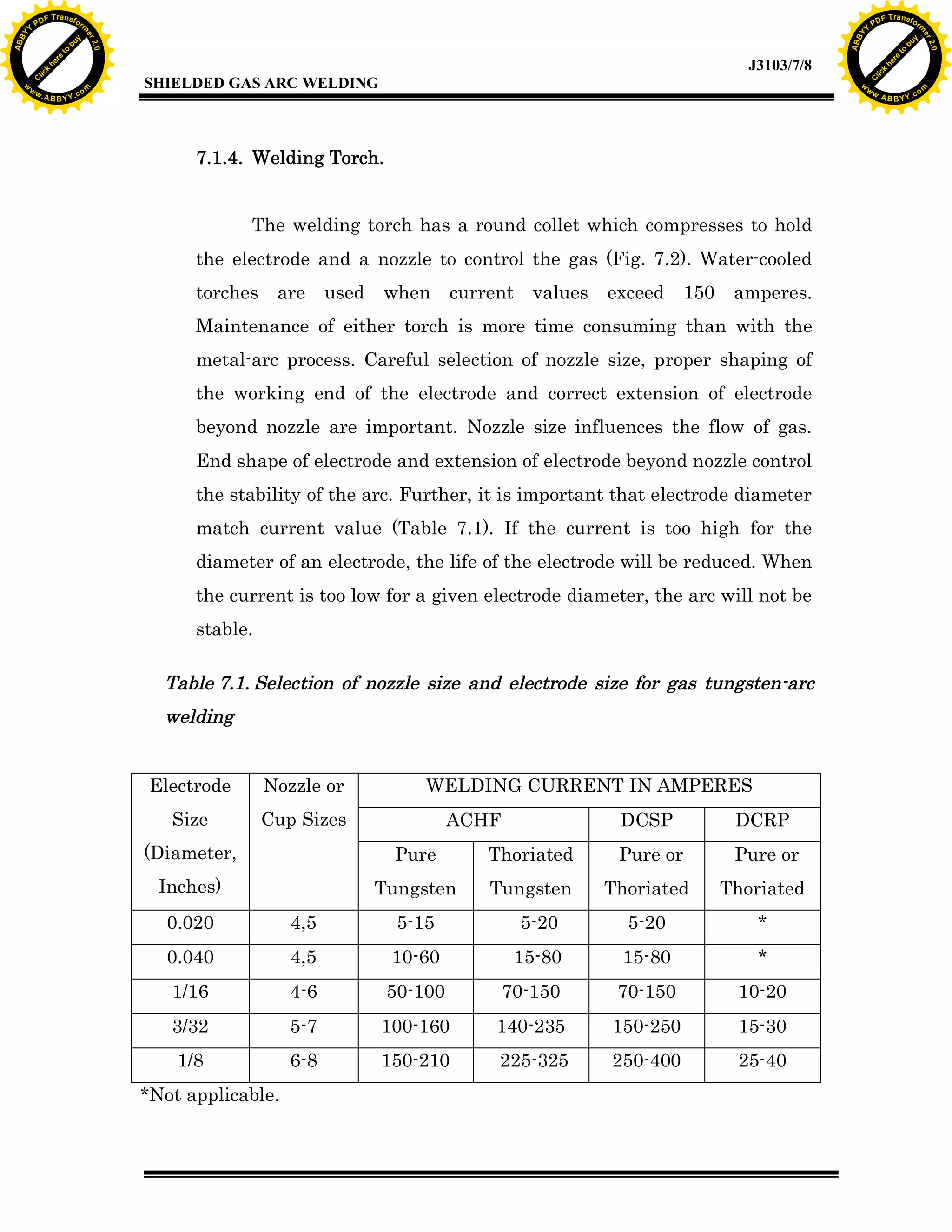
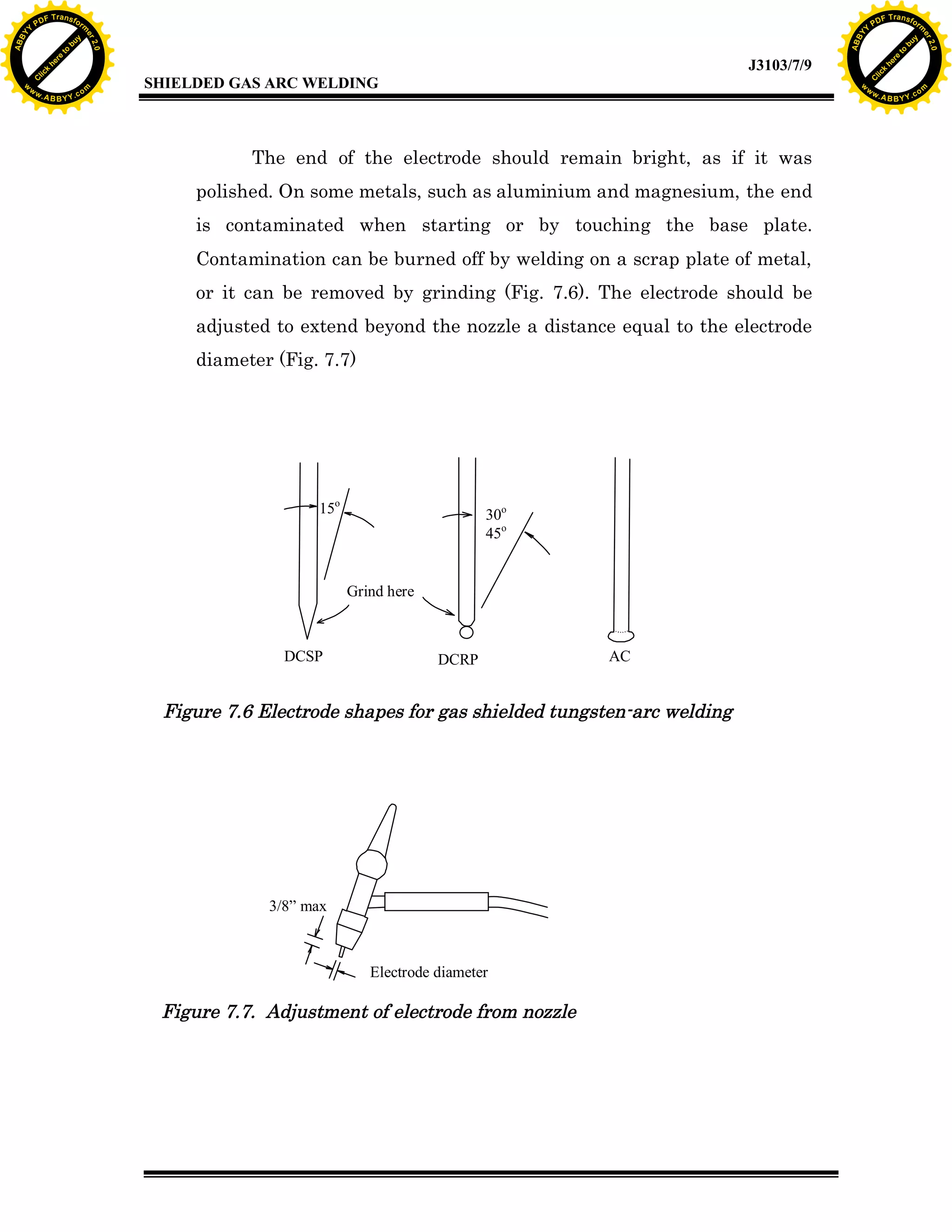
Discusses the design and maintenance of the welding torch and proper electrode shaping.
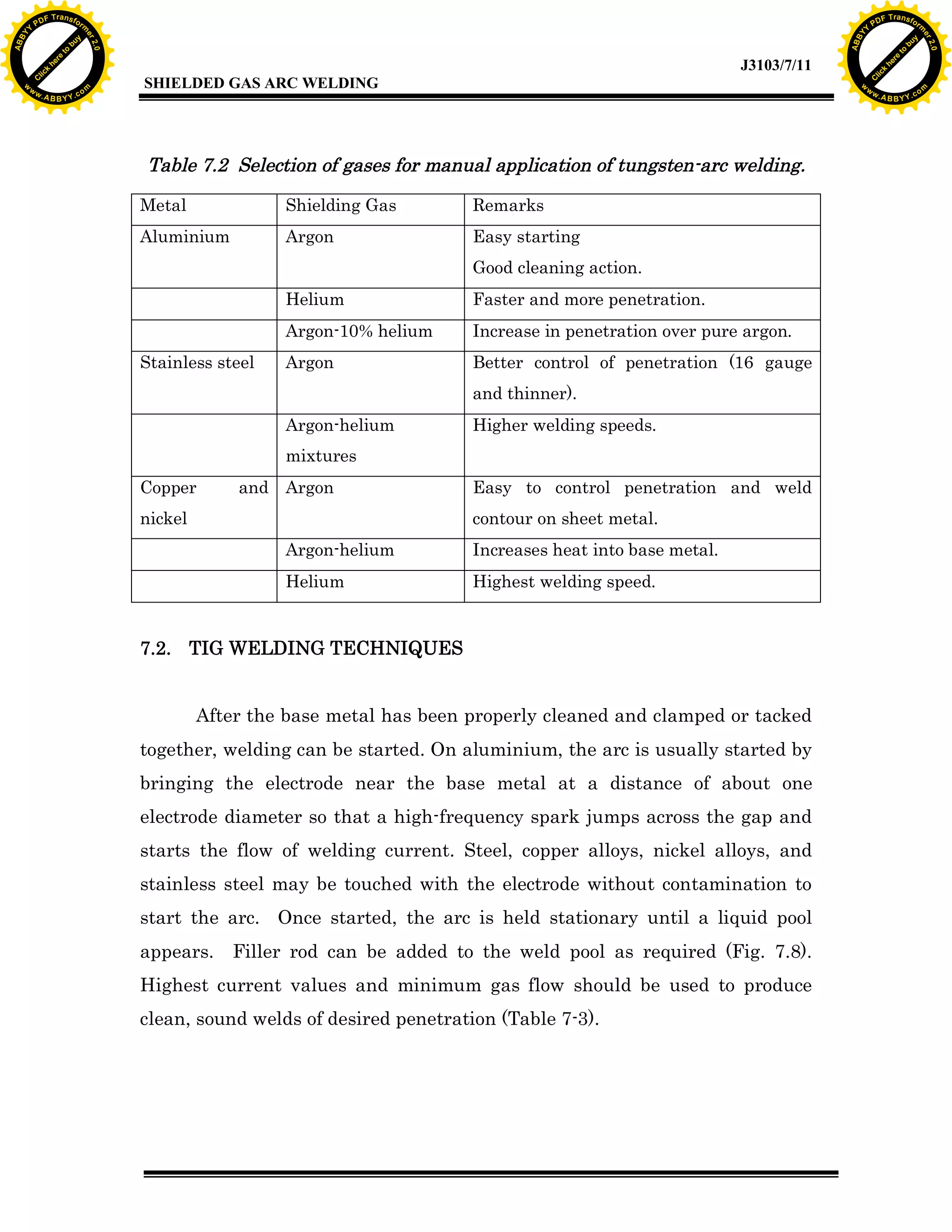
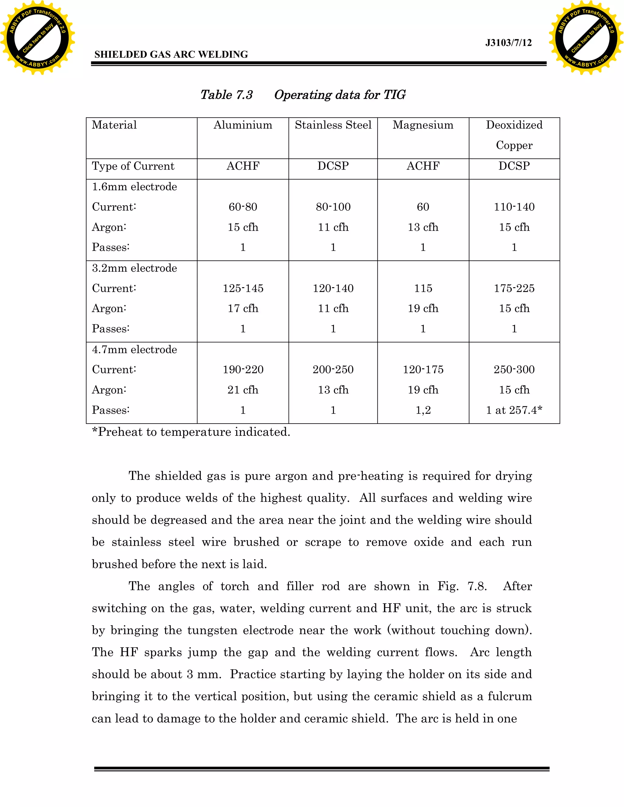
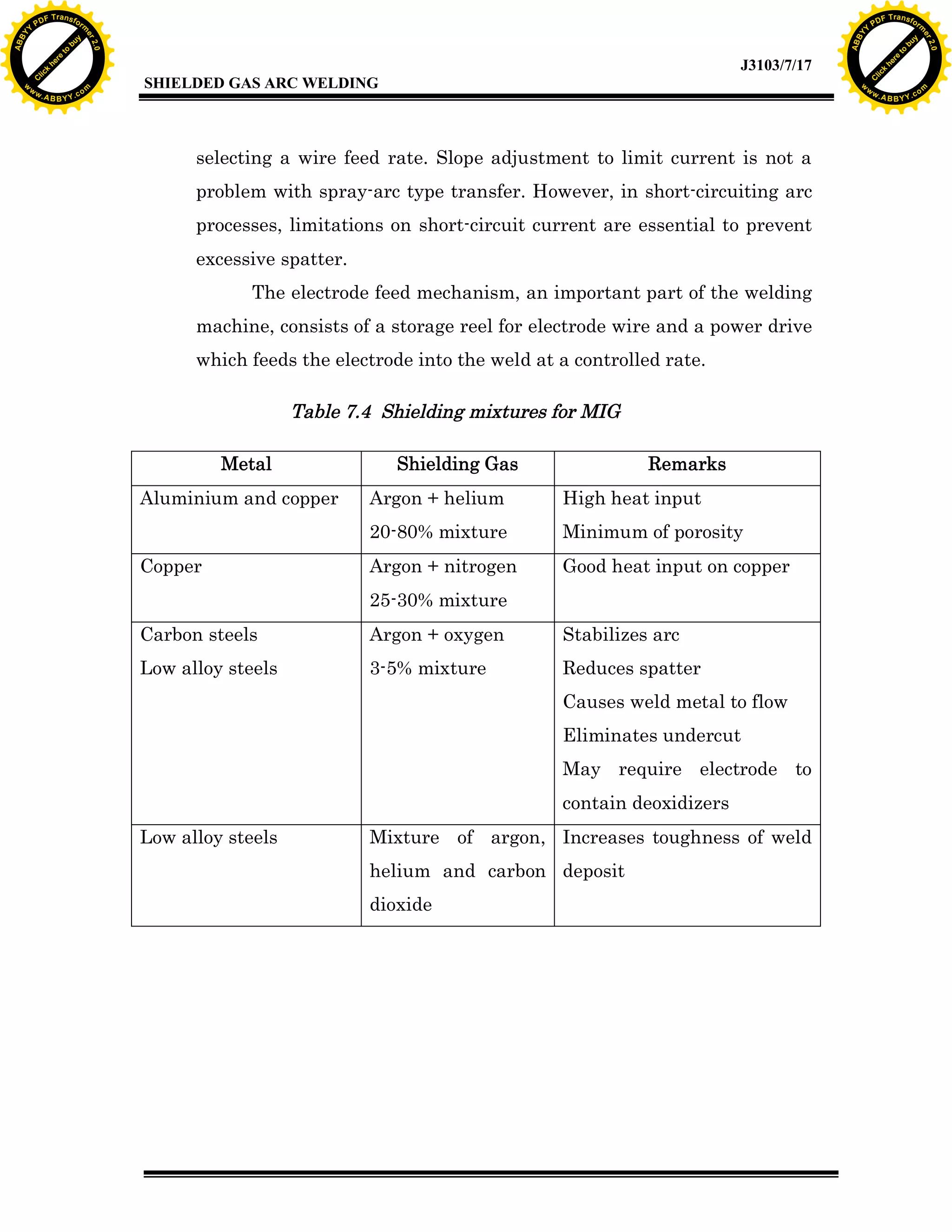
Types of shielding gases and filler metals for different materials, including application details.
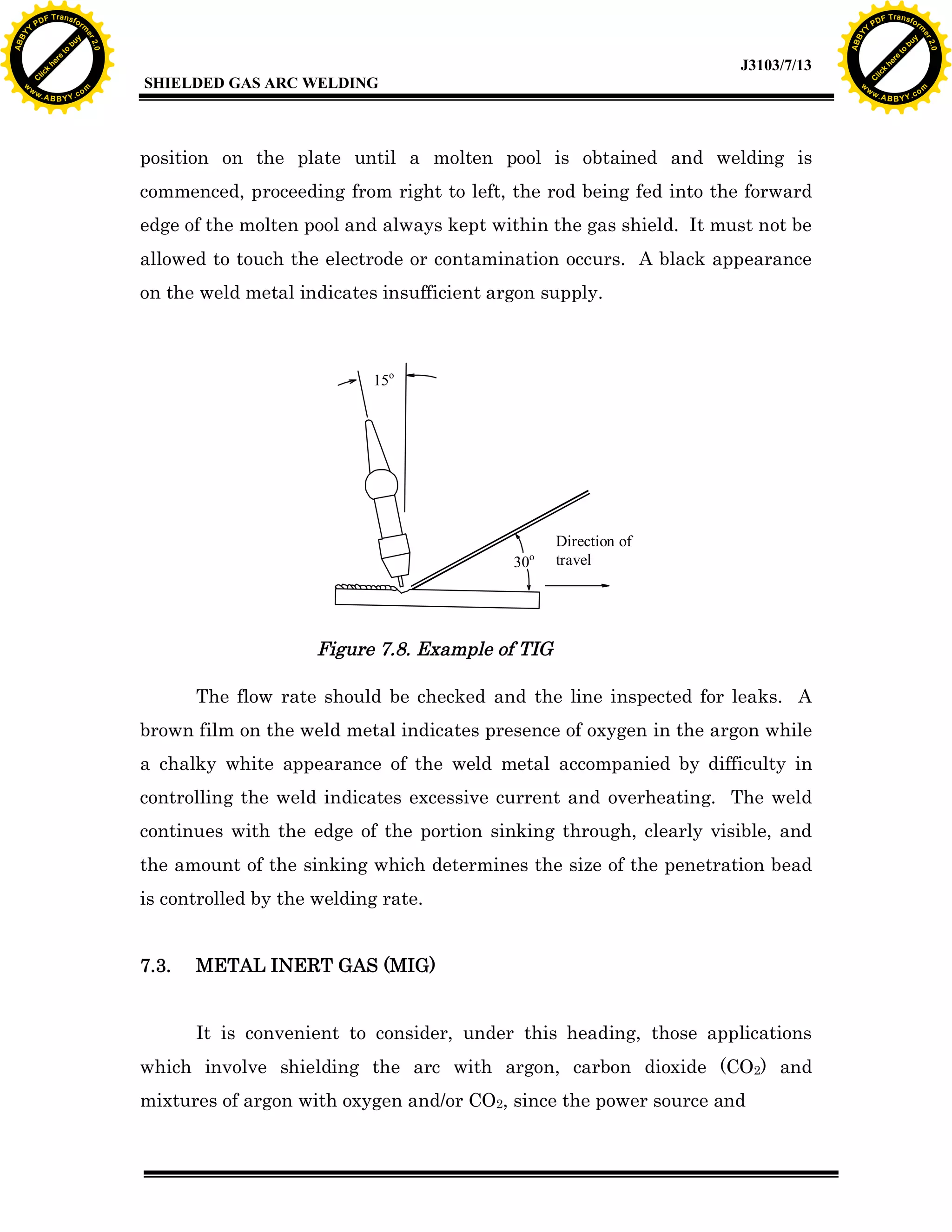
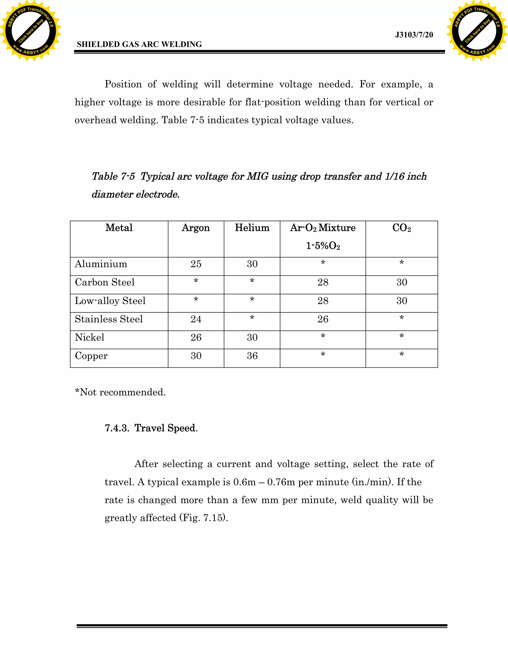
Details on operating techniques, including the process of creating the weld and common parameters.
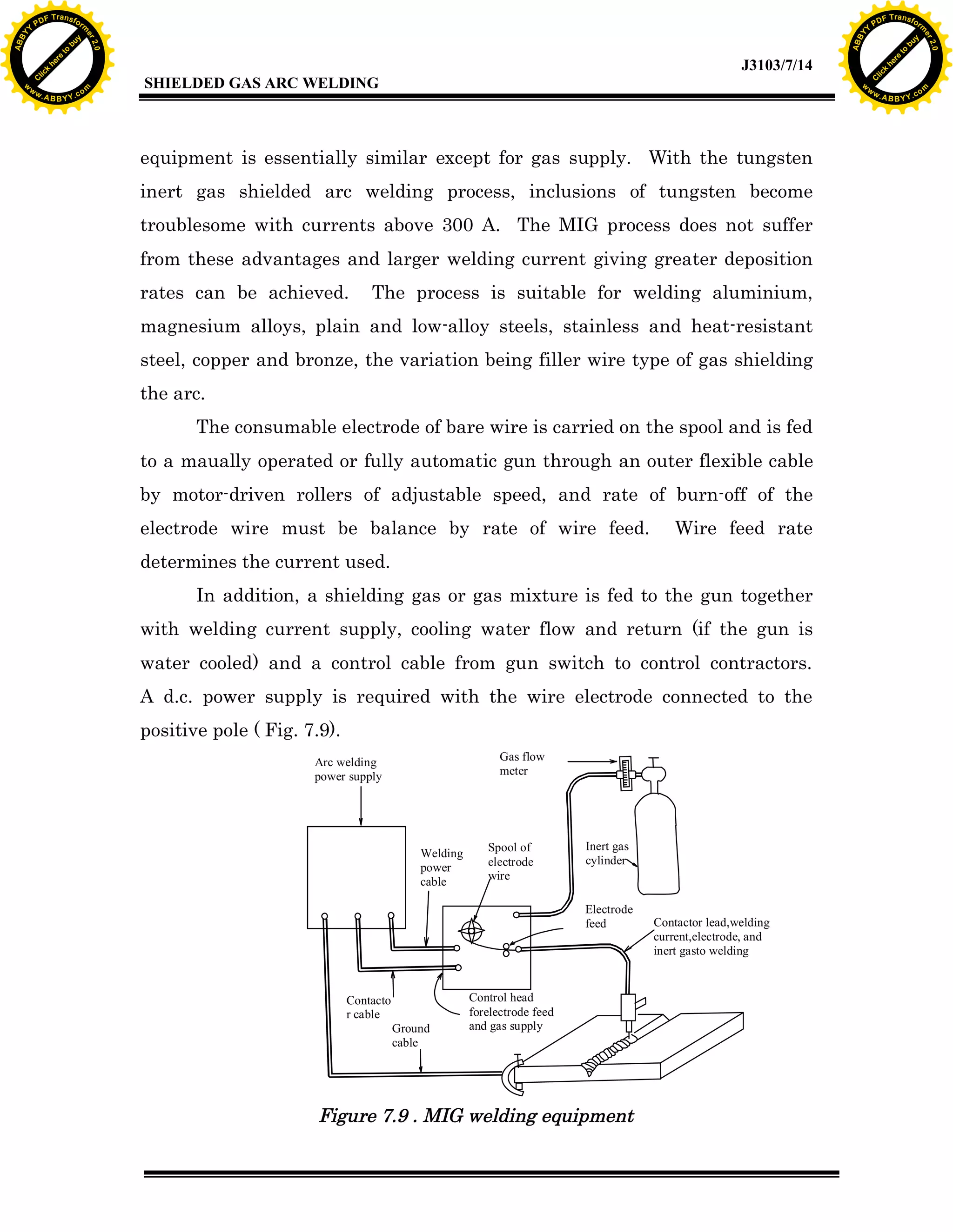
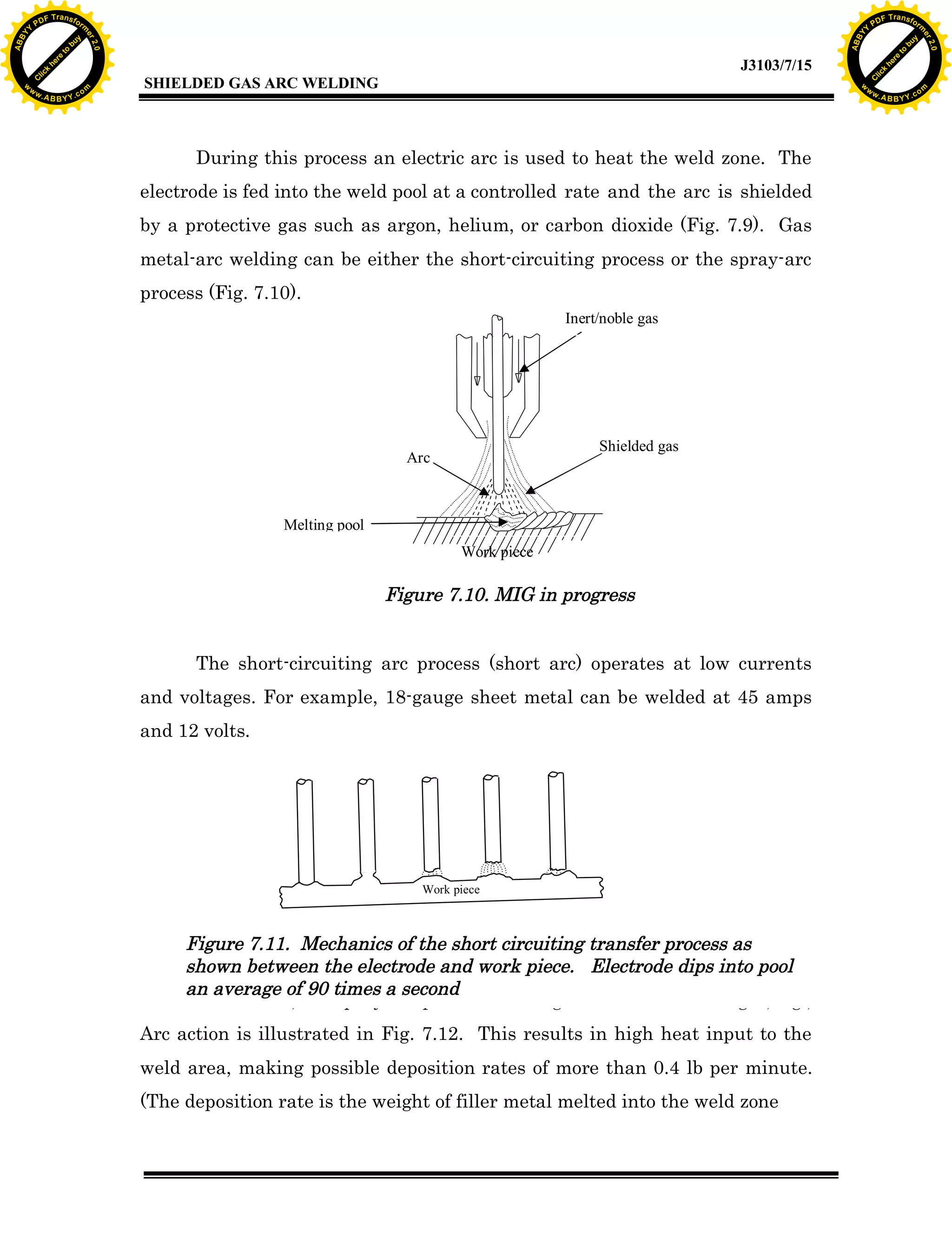
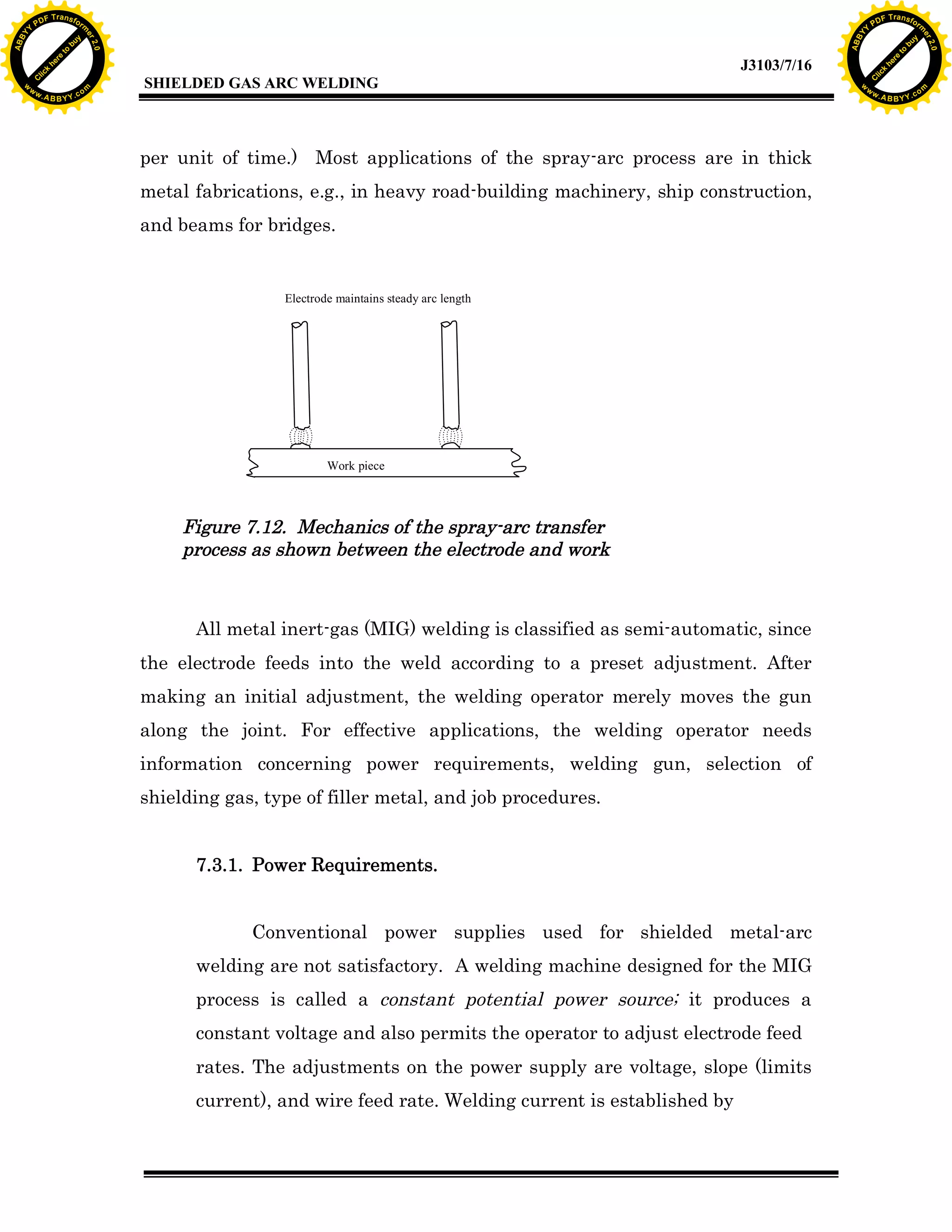
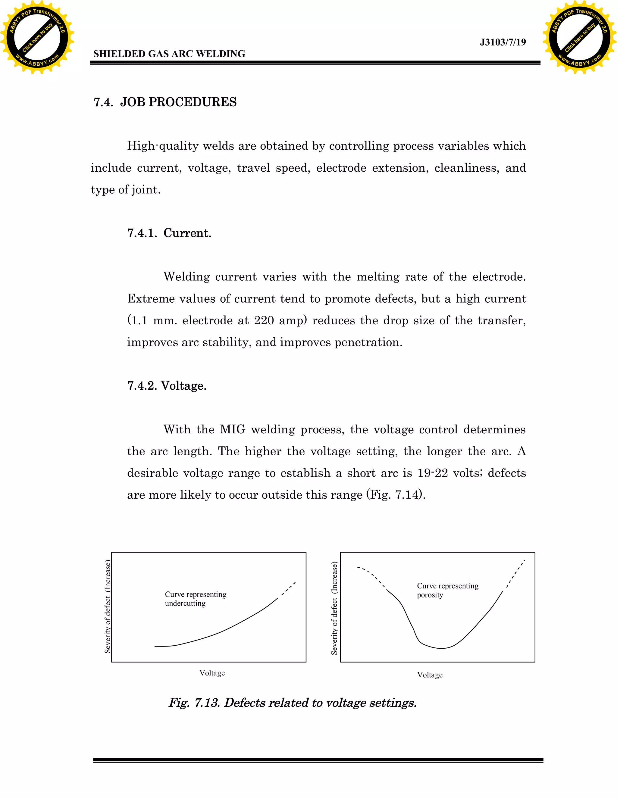
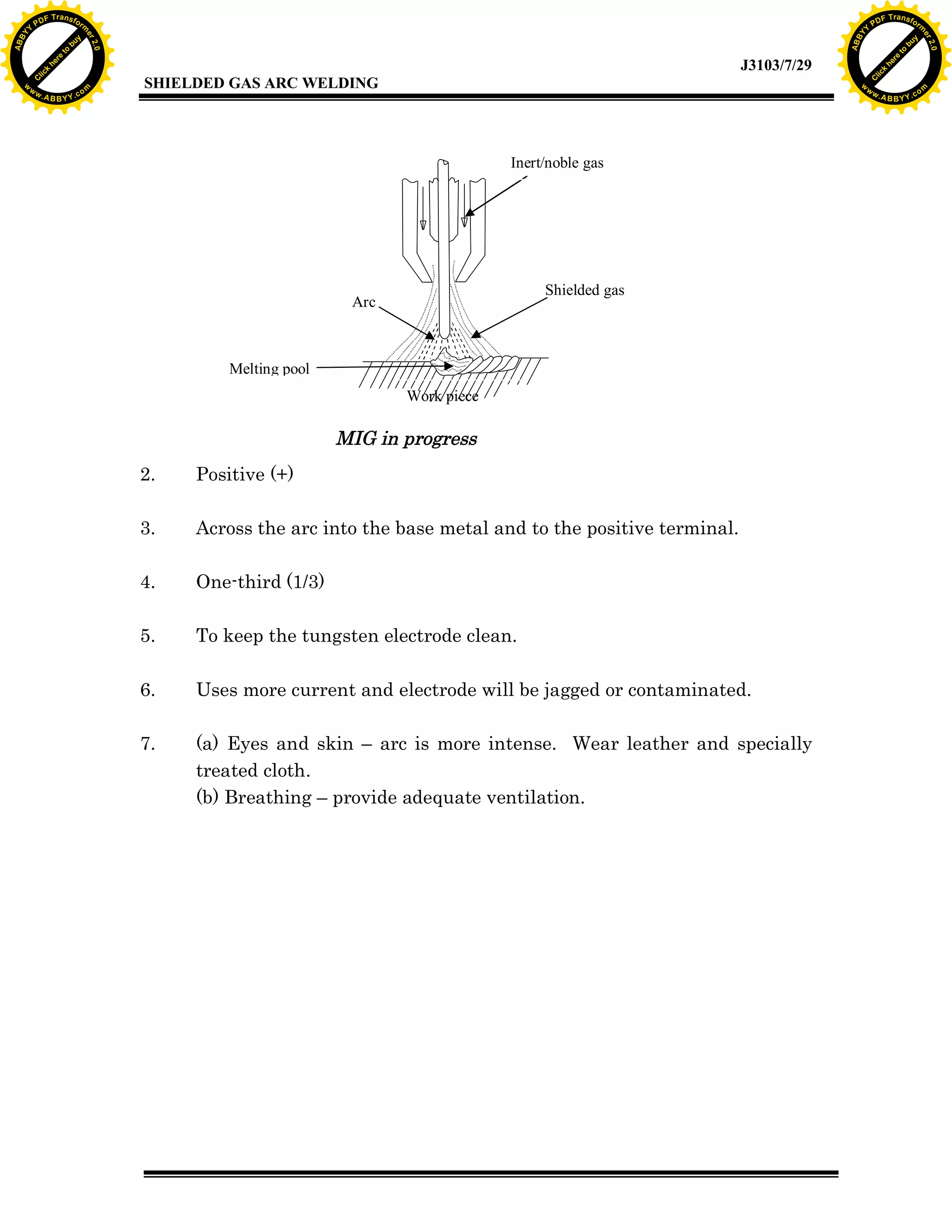
Introduction to MIG welding processes, equipment, shielding gases, and job procedures for effective welding.
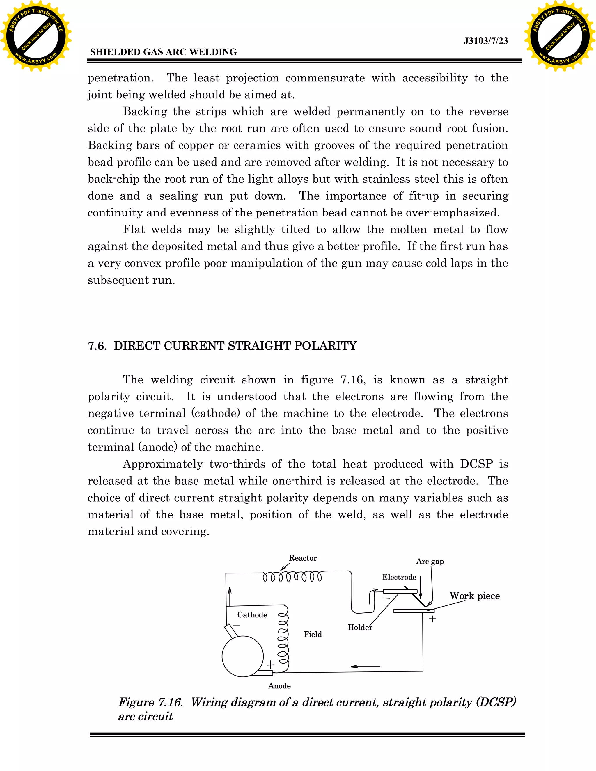
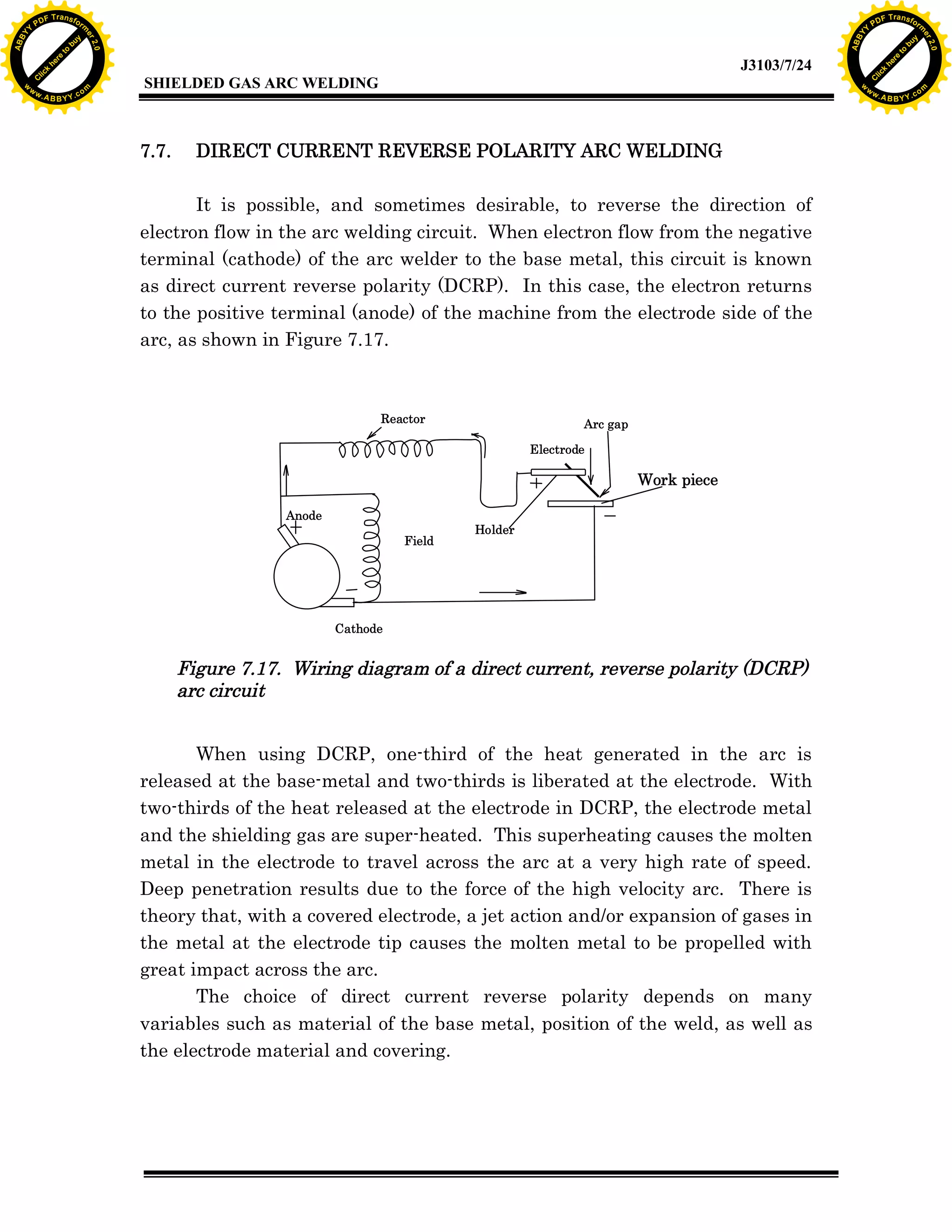
Explains the concepts of direct current straight and reverse polarity, impacts on welding quality.
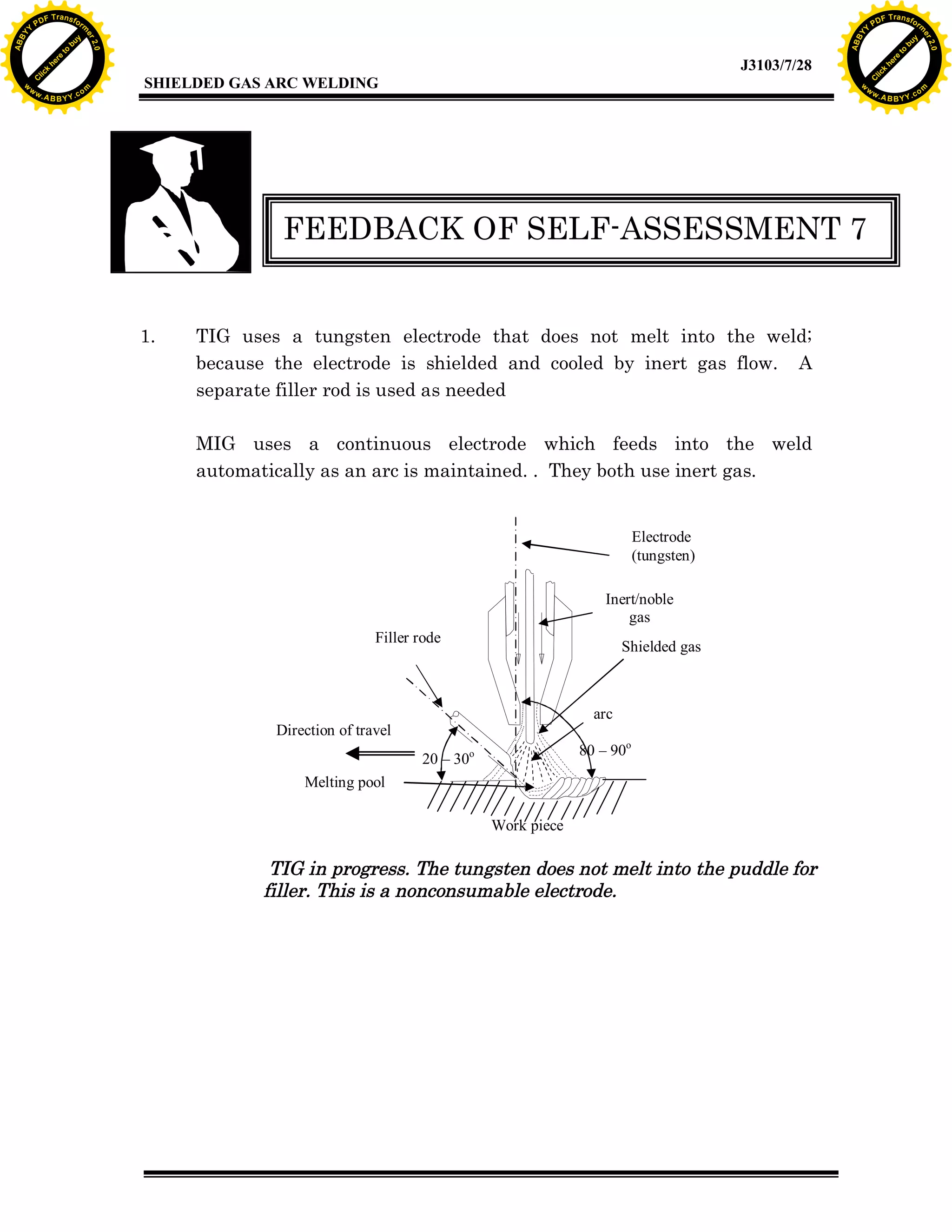
Activity prompts for self-assessment on TIG and MIG techniques, emphasizing the differences and applications.