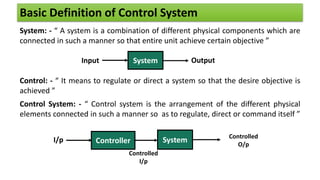
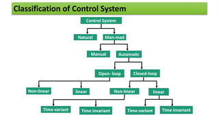
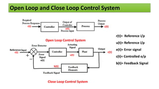
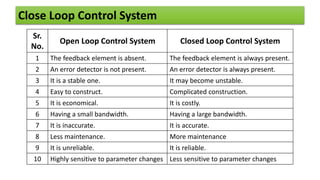
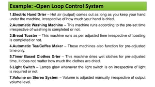
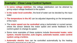
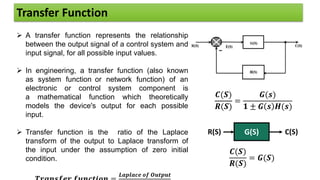
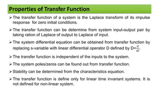
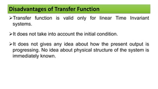
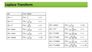
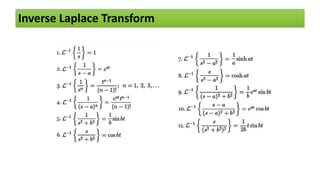
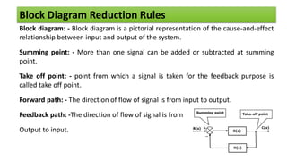
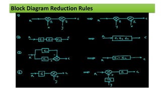
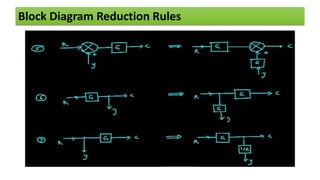
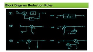
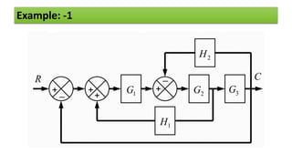
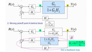
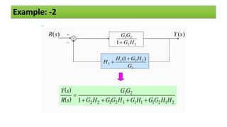
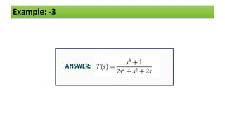
Electrical Engineering
Control
Systems
Basic Definition of Control System
System: - “ A system is a combination of different physical components which are
connected in such a manner so that entire unit achieve certain objective ”
Control: - “ It means to regulate or direct a system so that the desire objective is
achieved ”
Control System: - “ Control system is the arrangement of the different physical
elements connected in such a manner so as to regulate, direct or command itself ”
System
Input Output
System
I/p Controller
Controlled
I/p
Controlled
O/p
Classification of Control System
Control System
Natural Man-mad
Manual Automatic
Open- loop Closed-loop
Non-linear linear
Non-linear linear
Time-variant Time invariant Time-variant Time invariant
Open Loop and Close Loop Control System
Close Loop Control System
e(t)
u(t)
c(t)
b(t)
Reference
r(t)
Open Loop Control System
r(t) c(t)
u(t)
r(t)= Reference i/p
u(t)= Reference i/p
e(t)= Error signal
c(t)= Controlled o/p
b(t)= Feedback Signal
Close Loop Control System
Sr.
No.
Open Loop Control System Closed Loop Control System
1 The feedback element is absent. The feedback element is always present.
2 An error detector is not present. An error detector is always present.
3 It is a stable one. It may become unstable.
4 Easy to construct. Complicated construction.
5 It is economical. It is costly.
6 Having a small bandwidth. Having a large bandwidth.
7 It is inaccurate. It is accurate.
8 Less maintenance. More maintenance
9 It is unreliable. It is reliable.
10 Highly sensitive to parameter changes Less sensitive to parameter changes
Example: -Open Loop Control System
1.Electric Hand Drier – Hot air (output) comes out as long as you keep your hand
under the machine, irrespective of how much your hand is dried.
2.Automatic Washing Machine – This machine runs according to the pre-set time
irrespective of washing is completed or not.
3.Bread Toaster – This machine runs as per adjusted time irrespective of toasting
is completed or not.
4.Automatic Tea/Coffee Maker – These machines also function for pre-adjusted
time only.
5.Timer Based Clothes Drier – This machine dries wet clothes for pre-adjusted
time, it does not matter how much the clothes are dried.
6.Light Switch – Lamps glow whenever the light switch is on irrespective of light
is required or not.
7.Volume on Stereo System – Volume is adjusted manually irrespective of output
volume level.
Example: -Close Loop Control System
 In servo voltage stabilizer, the voltage stabilization can be attained by
giving output voltage feedback to the system
 In the water level controller, the level of water can be decided by the input
water
 The temperature in the AC can be adjusted depending on the temperature
of the room.
 The motor speed can be controlled using a tachometer or current sensor,
where the sensor detects the motor speed and sends feedback to the
control system to change its speed.
 Some more examples of these systems include thermostat heater, solar
system. missile launcher, auto engine, automatic toaster, water control
system using a turbine.
 Automatic electric iron can be controlled automatically by the heating
Transfer Function
 A transfer function represents the relationship
between the output signal of a control system and
input signal, for all possible input values.
 In engineering, a transfer function (also known
as system function or network function) of an
electronic or control system component is
a mathematical function which theoretically
models the device's output for each possible
input.
 Transfer function is the ratio of the Laplace
transform of the output to Laplace transform of
the input under the assumption of zero initial
condition.
𝑳𝒂𝒑𝒍𝒂𝒄𝒆 𝒐𝒇 𝑶𝒖𝒕𝒑𝒖𝒕
𝑪(𝑺)
𝑹(𝑺)
=
𝑮(𝒔)
𝟏 ± 𝑮 𝒔 𝑯(𝒔)
G(S) C(S)
R(S)
𝑪(𝑺)
𝑹(𝑺)
= 𝑮(𝑺)
Properties of Transfer Function
The transfer function of a system is the Laplace transform of its impulse
response for zero initial conditions.
The transfer function can be determine from system input-output pair by
taking ration of Laplace of output to Laplace of input.
The system differential equation can be obtained from transfer function by
replacing s-variable with linear differential operator D defined by D=
𝑑
𝑑𝑡
.
The transfer function is independent of the inputs to the system.
The system poles/zeros can be found out from transfer function.
Stability can be determined from the characteristics equation.
The transfer function is define only for linear time invariant systems. It is
not defined for non-linear system.
Disadvantages of Transfer Function
Transfer function is valid only for linear Time Invariant
systems.
It does not take into account the initial condition.
It does not gives any idea about how the present output is
progressing. No idea about physical structure of the system is
immediately known.
Laplace Transform
Inverse Laplace Transform
Block Diagram Reduction Rules
Block diagram: - Block diagram is a pictorial representation of the cause-and-effect
relationship between input and output of the system.
Summing point: - More than one signal can be added or subtracted at summing
point.
Take off point: - point from which a signal is taken for the feedback purpose is
called take off point.
Forward path: - The direction of flow of signal is from input to output.
Feedback path: -The direction of flow of signal is from
Output to input.
Block Diagram Reduction Rules
Example: -1
Example: -1
Example: -1
Example: -2
Example: -2
Example: -3
Example: -3
Some important Signal flow graph terms
Definition of SFG :
“A signal flow graph is pictorial representation of a system, and it displays
graphically, the transmission of signal in a system”
It applied to time- invariant linear system.
Signal flow graph
Mason’s Gain Equation: -
Overall Transfer function = T.F. =
𝑪(𝒔)
𝑹(𝒔)
=
𝑷𝒊∆𝒊
∆
i= Number of forward path
𝑷𝒊= Gain of 𝒊𝒕𝒉 forward path
∆= System determinant and can be calculated as follows
∆= 1- ( sum of all individual loop gain including self loops)
+ ( sum of all gain products of two non – touching loops)
- (sum of all gain products of three non – touching loops)
+ ------------------------
∆𝒊= The value of ∆ for the part of graph not touching to the 𝒊𝒕𝒉
forward
path.
Block Diagram to Signal Flow Graph
Signal Flow Graph to Block Diagram
Signal Flow Graph from equations
𝑦2 = 𝑡21𝑦1 + 𝑡23𝑦3
𝑦3 = 𝑡32𝑦2 + 𝑡33𝑦3 + 𝑡31𝑦1
𝑦4 = 𝑡43𝑦3 + 𝑡42𝑦2
𝑦5 = 𝑡54𝑦4
𝑦6 = 𝑡65𝑦5+ 𝑡45𝑦4
Example: Signal flow graph
Sankalp Education, Ahmedabad | Gandhinagar Mo. 9974460008
Thank you

Control system basics, block diagram and signal flow graph

  • 1.
  • 2.
    Basic Definition ofControl System System: - “ A system is a combination of different physical components which are connected in such a manner so that entire unit achieve certain objective ” Control: - “ It means to regulate or direct a system so that the desire objective is achieved ” Control System: - “ Control system is the arrangement of the different physical elements connected in such a manner so as to regulate, direct or command itself ” System Input Output System I/p Controller Controlled I/p Controlled O/p
  • 3.
    Classification of ControlSystem Control System Natural Man-mad Manual Automatic Open- loop Closed-loop Non-linear linear Non-linear linear Time-variant Time invariant Time-variant Time invariant
  • 4.
    Open Loop andClose Loop Control System Close Loop Control System e(t) u(t) c(t) b(t) Reference r(t) Open Loop Control System r(t) c(t) u(t) r(t)= Reference i/p u(t)= Reference i/p e(t)= Error signal c(t)= Controlled o/p b(t)= Feedback Signal
  • 5.
    Close Loop ControlSystem Sr. No. Open Loop Control System Closed Loop Control System 1 The feedback element is absent. The feedback element is always present. 2 An error detector is not present. An error detector is always present. 3 It is a stable one. It may become unstable. 4 Easy to construct. Complicated construction. 5 It is economical. It is costly. 6 Having a small bandwidth. Having a large bandwidth. 7 It is inaccurate. It is accurate. 8 Less maintenance. More maintenance 9 It is unreliable. It is reliable. 10 Highly sensitive to parameter changes Less sensitive to parameter changes
  • 6.
    Example: -Open LoopControl System 1.Electric Hand Drier – Hot air (output) comes out as long as you keep your hand under the machine, irrespective of how much your hand is dried. 2.Automatic Washing Machine – This machine runs according to the pre-set time irrespective of washing is completed or not. 3.Bread Toaster – This machine runs as per adjusted time irrespective of toasting is completed or not. 4.Automatic Tea/Coffee Maker – These machines also function for pre-adjusted time only. 5.Timer Based Clothes Drier – This machine dries wet clothes for pre-adjusted time, it does not matter how much the clothes are dried. 6.Light Switch – Lamps glow whenever the light switch is on irrespective of light is required or not. 7.Volume on Stereo System – Volume is adjusted manually irrespective of output volume level.
  • 7.
    Example: -Close LoopControl System  In servo voltage stabilizer, the voltage stabilization can be attained by giving output voltage feedback to the system  In the water level controller, the level of water can be decided by the input water  The temperature in the AC can be adjusted depending on the temperature of the room.  The motor speed can be controlled using a tachometer or current sensor, where the sensor detects the motor speed and sends feedback to the control system to change its speed.  Some more examples of these systems include thermostat heater, solar system. missile launcher, auto engine, automatic toaster, water control system using a turbine.  Automatic electric iron can be controlled automatically by the heating
  • 8.
    Transfer Function  Atransfer function represents the relationship between the output signal of a control system and input signal, for all possible input values.  In engineering, a transfer function (also known as system function or network function) of an electronic or control system component is a mathematical function which theoretically models the device's output for each possible input.  Transfer function is the ratio of the Laplace transform of the output to Laplace transform of the input under the assumption of zero initial condition. 𝑳𝒂𝒑𝒍𝒂𝒄𝒆 𝒐𝒇 𝑶𝒖𝒕𝒑𝒖𝒕 𝑪(𝑺) 𝑹(𝑺) = 𝑮(𝒔) 𝟏 ± 𝑮 𝒔 𝑯(𝒔) G(S) C(S) R(S) 𝑪(𝑺) 𝑹(𝑺) = 𝑮(𝑺)
  • 9.
    Properties of TransferFunction The transfer function of a system is the Laplace transform of its impulse response for zero initial conditions. The transfer function can be determine from system input-output pair by taking ration of Laplace of output to Laplace of input. The system differential equation can be obtained from transfer function by replacing s-variable with linear differential operator D defined by D= 𝑑 𝑑𝑡 . The transfer function is independent of the inputs to the system. The system poles/zeros can be found out from transfer function. Stability can be determined from the characteristics equation. The transfer function is define only for linear time invariant systems. It is not defined for non-linear system.
  • 10.
    Disadvantages of TransferFunction Transfer function is valid only for linear Time Invariant systems. It does not take into account the initial condition. It does not gives any idea about how the present output is progressing. No idea about physical structure of the system is immediately known.
  • 11.
  • 12.
  • 13.
    Block Diagram ReductionRules Block diagram: - Block diagram is a pictorial representation of the cause-and-effect relationship between input and output of the system. Summing point: - More than one signal can be added or subtracted at summing point. Take off point: - point from which a signal is taken for the feedback purpose is called take off point. Forward path: - The direction of flow of signal is from input to output. Feedback path: -The direction of flow of signal is from Output to input.
  • 14.
  • 15.
  • 16.
  • 17.
  • 18.
  • 19.
  • 20.
  • 22.
  • 23.
  • 24.
  • 25.
    Some important Signalflow graph terms Definition of SFG : “A signal flow graph is pictorial representation of a system, and it displays graphically, the transmission of signal in a system” It applied to time- invariant linear system.
  • 26.
    Signal flow graph Mason’sGain Equation: - Overall Transfer function = T.F. = 𝑪(𝒔) 𝑹(𝒔) = 𝑷𝒊∆𝒊 ∆ i= Number of forward path 𝑷𝒊= Gain of 𝒊𝒕𝒉 forward path ∆= System determinant and can be calculated as follows ∆= 1- ( sum of all individual loop gain including self loops) + ( sum of all gain products of two non – touching loops) - (sum of all gain products of three non – touching loops) + ------------------------ ∆𝒊= The value of ∆ for the part of graph not touching to the 𝒊𝒕𝒉 forward path.
  • 27.
    Block Diagram toSignal Flow Graph
  • 28.
    Signal Flow Graphto Block Diagram
  • 29.
    Signal Flow Graphfrom equations 𝑦2 = 𝑡21𝑦1 + 𝑡23𝑦3 𝑦3 = 𝑡32𝑦2 + 𝑡33𝑦3 + 𝑡31𝑦1 𝑦4 = 𝑡43𝑦3 + 𝑡42𝑦2 𝑦5 = 𝑡54𝑦4 𝑦6 = 𝑡65𝑦5+ 𝑡45𝑦4
  • 30.
  • 31.
    Sankalp Education, Ahmedabad| Gandhinagar Mo. 9974460008 Thank you