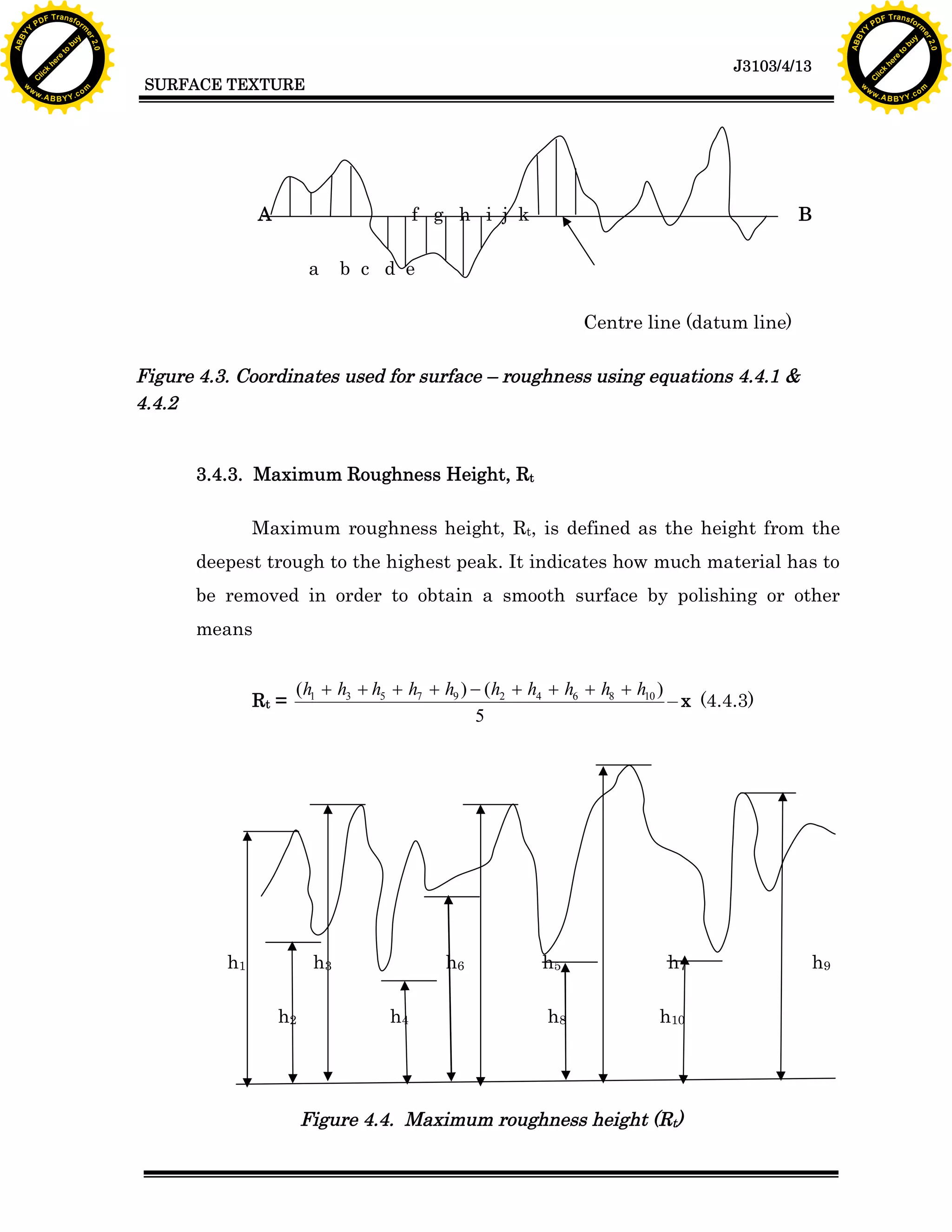
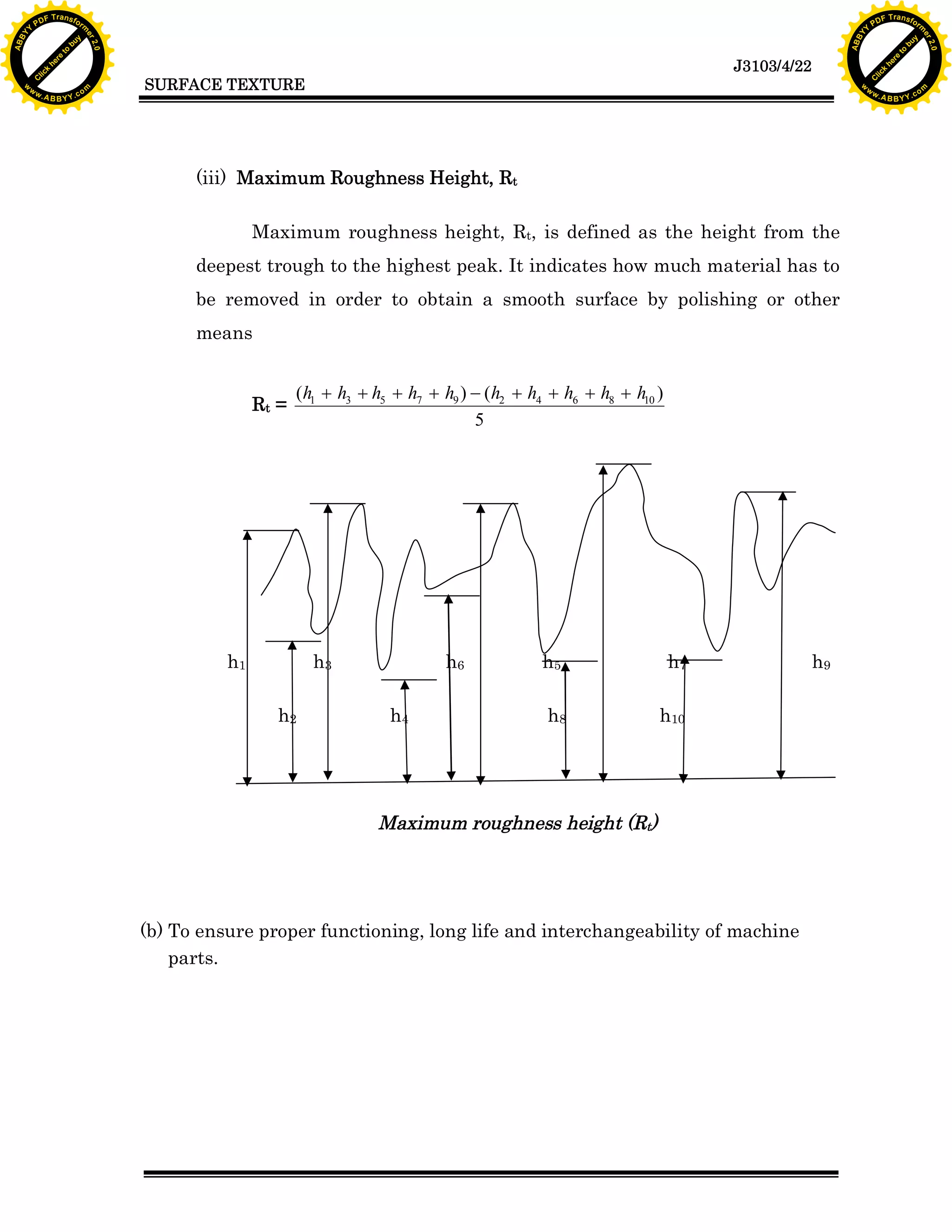
bu
to
re
he
k
w
A
lic
C
SURFACE TEXTURE
rm
y
ABB
to
re
he
J3103/4/13
k
lic
C
w.
om
w
w
w
Y
2.0
2.0
bu
y
rm
er
Y
F T ra n sf o
ABB
PD
er
Y
Rt is defined as the maximum height of the roughness profile. It is the
vertical distance between the
The document discusses surface finish and roughness measurement. It defines terms like surface texture, roughness, waviness, and provides explanations of different measurement methods and parameters like Ra, Rz, and Rmax. Measurement methods covered include comparison methods, profilometers, and instruments like the Taylor-Hobson Talysurf that can numerically analyze surface roughness.
The document discusses surface finish of engineering components. It defines terms like surface roughness, actual profile, reference profile, datum profile, mean profile, peak to valley height and mean roughness index which are used to characterize the geometrical properties of a surface. It also discusses different methods to measure and represent surface roughness values and grades on engineering drawings.
This document provides information on reinforcement detailing according to Eurocode 2 (EC2). It begins with an overview of the structural Eurocodes and the contents of EC2. Key topics covered in more detail include reinforcement properties, minimum cover requirements, crack control, bar spacing, bond stress calculations, and the design of anchorage and lap lengths. Worked examples are provided to demonstrate how to calculate the design anchorage length for tension reinforcement according to the equations and factors specified in EC2. In summary, the document outlines the main requirements for reinforcement detailing in concrete structures as defined by EC2.
This document discusses measurement of surface finish. It begins with basic concepts of surface roughness and factors that influence surface finish like machining variables, tool geometry, workpiece and tool materials. It describes different types of surface irregularities from first to fourth order. There are two main methods to measure surface finish - qualitative methods like visual inspection and quantitative methods using instruments like stylus profilometers. Key parameters to analyze surface roughness include Ra, Rz, and RMS. Surface roughness is important for functions like friction, wear and lubrication.
Guide to the design and construction of reinforced concrete flat slabs (1)abbdou001
This document provides guidance on the design and construction of reinforced concrete flat slabs according to Eurocode standards. It discusses factors that influence flat slab design and construction such as the type of structure, client requirements, planning rules, ground conditions, and contractor preferences. It also covers typical flat slab behavior, design considerations, construction methods, detailing, and analysis techniques. The document aims to help designers understand flat slab structural behavior and best practices for design and construction.
Datum targets are symbols used on drawings to represent the shape, size, and location of gauge elements used to establish datum planes or axes, even though the targets do not physically exist on the part. There are three basic datum target symbols - for points, lines, and areas. Datum targets allow establishing a repeatable relationship between a part and gauge for inspection and assembly.
Design of concrete structure 2 project-Loay Qabaha &Basel SalameLoay Qabaha
This document provides a design for a two-way ribbed slab system. It begins by defining two-way slab systems and providing structural equations. It then gives the problem definition, including load data. The slab is designed by first assuming a thickness and checking loads and shear. Reinforcement is designed. Frame analysis is done by hand and in SAP2000 to calculate moments, which are within 5% error. Design details like steel areas are attached in an Excel sheet.
The document discusses factors that affect surface finish, methods for measuring surface finish, and ways to represent surface roughness specifications. It describes that the material, machining type, tooling, and cutting conditions can influence surface finish. Methods for measuring finish include comparison to standards, using a profilometer, profilograph, or other instruments. Surface roughness can be specified via standard grades, numerical values, or symbols added to drawings.
IJRET : International Journal of Research in Engineering and Technology is an international peer reviewed, online journal published by eSAT Publishing House for the enhancement of research in various disciplines of Engineering and Technology. The aim and scope of the journal is to provide an academic medium and an important reference for the advancement and dissemination of research results that support high-level learning, teaching and research in the fields of Engineering and Technology. We bring together Scientists, Academician, Field Engineers, Scholars and Students of related fields of Engineering and Technology
This document summarizes the design of the reinforcement for an interior bay of a two-way flat plate concrete slab system. The slab was designed using the ACI 318 Direct Design Method. Reinforcement details and quantities are provided for welded wire reinforcement in both short and long slab directions. The steel weight per square foot using welded wire reinforcement is 1.93 lbs, compared to 2.51 lbs using grade 60 rebar, representing a 23% savings in steel weight.
There are three main stages of setting out that must be carried out for construction projects:
1. Initial setting out of the site limits and boundaries
2. Setting out the foundations and major site elements in the first stage
3. Setting out precise design points and dimensions in the second stage
Horizontal and vertical control points must be established to accurately position all design aspects according to the drawings and specifications. Proper planning and protection of control points is important to ensure correct construction.
1) There are several methods for accurately setting out and measuring angles on a construction site, including using a builders square, the 3:4:5 method, optical equipment, and satellite navigation.
2) Setting out a rectangular building involves establishing corner points and boundary lines, measuring lengths and checking for square corners using the building diagonals.
3) Temporary corner profiles are erected and marked with setting out lines to aid in transferring measurements underground once excavation is complete.
This document discusses surface metrology and surface texture. It provides definitions of key terms like roughness, waviness, and flaws. It describes how surface texture is influenced by manufacturing processes and factors like material, cutting tools, and cutting conditions. Methods for measuring and specifying surface texture are outlined, including peak-to-valley height, average roughness, form factor, and bearing curve analysis. Direct instrument methods to measure surface finish are also summarized, such as using a profilometer, Tomlinson surface tester, and Taylor-Hobson-Talysurf surface roughness tester.
This document outlines the aims, learning outcomes, and content of a module on engineering surveying for a National Diploma in Industrial Technician for civil engineering. The 120-hour module aims to introduce students to basic surveying techniques and instruments, develop skills in using this equipment, and apply surveying practices to construction projects. Key topics covered include linear measurement, levelling, compass traversing, setting out structures, and calculating areas. Assessment is through continuous assessment.
New microsoft office power point presentationgeometrical toleranceSrinivas Narayana
A geometric tolerance specifies the allowable variation in geometric form, orientation, or location of a feature. There are three main types of geometric tolerances: form tolerances which define straightness, circularity, flatness, or cylindricity; orientation tolerances which define perpendicularity, parallelism, or angularity; and position tolerances which define position, symmetry, or concentricity. A geometric tolerance is prescribed using a feature control frame that specifies the tolerance symbol, tolerance value, and datum references.
A Study of Reduced Beam Section Profiles using Finite Element AnalysisIOSR Journals
Abstract: Reduced beam section (RBS) is one of the several connection types, which is economical and
popular for use in new steel moment frame structures in seismic zone. To form RBS connection, some portion of
the beam flanges at a short distance from column face is purposefully trimmed so that the yielding and plastic
hinge occurs within this area of flanges. Use of RBS connection is found advantageous due to: a) the shear
force in the panel zone is reduced; b) the force demand in column continuity plates i.e. stiffeners are reduced;
and c) strong-column – weak-beam requirement is satisfied. Although, radius cut RBS is qualified by
ANSI/AISC, FEMA codes, various flange cut shapes like constant, tapered, radius cut, drilled holes are possible
to reduce the cross sectional area of beam flanges. The purpose of this study is to understand behavior of RBS
beam-to-column moment connections for various flange cut geometries. This document represents nonlinear
finite element analysis of the connection models performed using the computer program, ANSYS/Multiphysics
Keywords - Steel structures, steel connections, reduced beam section, RBS profiles
The document discusses reference frames and datums, including:
- A datum is a theoretically exact point, axis, line or plane used to define the geometric relationships between tolerance zones and the datum reference frame.
- Datum feature simulators are used to establish datums and have characteristics like perfect form and basic orientation/location.
- Common datum features include planar surfaces using 3 datum planes, inclined surfaces oriented at the basic angle, and cylindrical features using planes and axes.
- Datum modification symbols like MMB and LMB are used to define the material condition of a datum feature.
- Datum targets, indicated by symbols, are used to establish datums where full surfaces cannot be due to irregularities and include points,
This document discusses the design of two-way floor slab systems. It compares the behavior of one-way and two-way slabs, describing how two-way slabs carry load in two directions versus one direction for one-way slabs. Different two-way slab systems like flat plates, waffle slabs, and ribbed slabs are described. Methods for analyzing two-way slabs include direct design, equivalent frame, elastic, plastic, and nonlinear analysis. Design considerations like minimum slab thickness are discussed along with examples calculating thickness.
This document summarizes a lecture on flat slab design and analysis. It discusses key topics such as:
1. Definitions of flat slabs and their components like column strips and middle strips.
2. Methods of analyzing flat slabs including numerical methods and manual methods like the method of substitutive beams.
3. Design considerations for flat slabs including steel distribution above columns, welded mesh reinforcement, loading schemes, and punching shear design.
4. Different types of shear reinforcement that can be used at column heads like links, cages, and bent-up bars.
This document provides design details for the reinforcement of a 300mm thick flat slab with 4.5m spacing between columns. The slab is for an office with a specified imposed load of 1kN/m2 for finishes and 4kN/m2 imposed. Perimeter load is assumed to be 10kN/m. Concrete strength is C30/37. Analysis and design is carried out for grid line C, which is considered as a 6m wide bay. Reinforcement requirements are calculated for flexure, deflection, punching shear, and transfer of moments to columns. Reinforcement arrangements are proposed to meet the calculated requirements.
This document summarizes the key aspects of flat slab construction and design according to Indian code IS 456-2000. It defines flat slabs as slabs that are directly supported by columns without beams, and describes four common types based on whether drops and column heads are used. The main topics covered include guidelines for proportioning slabs and drops, methods for determining bending moments and shear forces, requirements for slab reinforcement, and an example problem demonstrating the design of an interior flat slab panel.
Geometric Dimensioning and Tolerance (GD&T) defines the allowable shape variations for features using geometric tolerances rather than just size tolerances. There are three main types of geometric tolerances - form, orientation, and position tolerances. Geometric tolerances are specified using a feature control frame containing a tolerance symbol, value, and optional datum reference. Material condition modifiers indicate if the tolerance applies at maximum, least, or regardless of material size.
Flat Plate Slab Design for B.Sc. in Civil Engg Students
By: Md.Mahbub Ul Alam, Asst Prof, Dept. of Civil Engg.
Stamford University Bangladesh.
Uploaded at www.sladeshare.net.
This document provides information about geometric dimensioning and tolerancing (GD&T). It defines GD&T as a method for defining the geometry of a part beyond simple tolerance dimensions. Feature control frames modify a part's geometry and include the geometric tolerance symbol, datum, and modifiers. Geometric characteristic symbols indicate the type of tolerance such as flatness, circularity, or perpendicularity. Datums establish the reference frame for measurements and include primary, secondary, and tertiary datums indicated on drawings.
Introduction to Geometric Dimensioning and Tolerancing (GD&T)Kapil Mukund
This document provides an introduction to geometric dimensioning and tolerancing (GD&T). It defines GD&T and explains that it uses international symbols and standards to accurately describe parts in three dimensions. The document outlines the history and development of GD&T and explains its key advantages like reducing costs and improving quality. It also describes the different GD&T elements like form tolerances, profile tolerances, orientation tolerances, location tolerances, and runout tolerances. Standards bodies like ASME and ISO are discussed and examples of common GD&T symbols are provided.
This document provides an overview of geometric dimensioning and tolerancing (GD&T). It defines three categories of dimensioning: general, geometric, and surface texture. GD&T is important as it saves money by reducing unnecessary inspection of features, ensures interchangeability, and provides a universal understanding of symbols. GD&T should be used when part features are critical to function or interchangeability. The document provides examples of when and how to apply GD&T to features such as flatness, straightness, and circularity.
Unit ini membahas masalah-masalah utama dalam sistem hidraulik seperti kesan beban dan kelajuan berlebihan pada pompa yang dapat mengurangkan umur komponen, masalah peronggaan akibat pengendalian yang tidak tepat, kebocoran sistem, dan masalah pada silinder seperti kebocoran dan kelambatan gerakan. Dokumen ini juga menjelaskan panduan untuk memilih cairan hidraulik yang ideal berdasarkan sifatnya se
This document is an introduction to the book "Thiaoouba Prophecy" which details reported events that the author, Michel Desmarquet, claims to have experienced personally. He describes being taken from his home by a being named Thao, who explains to him that he has been brought to a parallel universe where time is suspended. In this parallel universe, people from Earth who were accidentally transported there through natural "warps" between universes can exist indefinitely without aging. The introduction sets up the unusual story that Desmarquet then plans to recount from his experiences.
1) The document discusses the principles of shielded gas arc welding, specifically TIG and MIG welding. It aims to explain the techniques, equipment, and advantages/disadvantages of each process.
2) TIG welding uses a non-consumable tungsten electrode within an inert gas shield to produce an arc for welding. MIG welding uses a consumable wire electrode and an inert gas shield.
3) The document covers TIG welding equipment, joint preparation, power sources, torch design, and electrode selection. It also briefly discusses MIG welding.
The document is a chapter from a story that describes a young monk visiting an old blind hermit for instruction. The hermit recounts how, after being tortured and wandering blind, he was taken to a shrine where beings told him they were "Gardeners of the Earth" who travel between universes. They healed the hermit and told him they would reveal the true origins of life on Earth so he could pass this knowledge to others. The hermit is now sharing this story with the young monk so he can spread the message to the world.
The document discusses various methods for measuring elements of screw threads, including:
1) Major diameter can be measured using a micrometer.
2) Minor diameter can be measured using a micrometer with shaped anvils or micrometer and vee pieces.
3) Mean diameter is best measured using the three-wire method with a micrometer.
4) An optical comparator can also be used to check thread form by projecting an enlarged shadow.
1. The document discusses divisibility rules and properties of numbers including: a) If b divides a and c divides b, then c divides a. b) The greatest common divisor (GCD) of two numbers is the largest positive integer that divides both numbers. c) The GCD of a and b is the largest number that divides both a and b completely with no remainder.
2. Examples are provided to illustrate divisibility rules for various numbers. For numbers like 9, 3 divides it and the quotient is an integer, so its number is divisible by 3.
3. The Euclidean algorithm is described as a method to efficiently find the GCD of two numbers a and b by repeatedly finding the remainder
Control charts are statistical tools used to monitor processes and distinguish between common and special cause variations. They graphically display process stability over time and can provide early warnings if a process becomes out of control. The X-bar and R chart is used for variables data with subgroup sizes of 2-15. It involves calculating the mean and range for each subgroup, then determining control limits based on the grand mean and average range. Patterns outside the control limits or showing trends over time indicate the process may need investigation.
The document provides an introduction to relays and contactors. It defines relays as electromagnetically actuated switches that use a magnetic field created by a coil to switch contacts. Relays are used to switch small outputs and currents, while contactors are used to switch larger outputs and currents. The document discusses relay and contactor symbols, diagrams, types, and provides a comparison of their key differences. Specifically, it notes that relays have a clapper-type armature and single contact separation, while contactors have a lifting armature and double contact separation.
This document provides an overview of quality concepts including definitions of quality, zero defects, customers, quality terms and concepts, inspection, sampling, and the differences between SPC and acceptance sampling. It defines quality as meeting customer expectations and conforming to specifications. Zero defects aims for no product or service defects. Customers are critical to quality and satisfaction. Total quality management, continuous improvement, six sigma, and PDCA model are quality approaches. Inspection and sampling are used to check for defects. SPC monitors processes while acceptance sampling accepts or rejects lots.
The document discusses attribute control charts which are used to monitor quality characteristics that can only have discrete responses like pass/fail rather than continuous variable measurements. It provides information on the different types of attribute control charts including P, NP, C, and U charts. The key steps for constructing these charts are outlined which include collecting data, calculating control limits, and plotting sample points to check if the process is in control. Formulas for calculating control limits of each chart type are also presented along with examples of how to construct and interpret P, NP, C and U charts.
This document discusses acceptance sampling, which is used to determine whether to accept or reject a sample based on predetermined quality levels. It defines key terms and outlines the advantages and disadvantages. Various sampling plans are described, including single, double, and multiple sampling plans. The operating characteristic curve is explained as a graph showing the probability of accepting lots at various quality levels. Producers' and consumers' risks are defined. Examples are provided to demonstrate calculating acceptance probabilities using Poisson distributions and constructing operating characteristic curves.
This document summarizes key concepts related to surface quality and accuracy in machining. It defines different aspects of surface texture including roughness, waviness, lay, and flaws. It describes common methods for measuring and characterizing surface roughness numerically and visually. Surface roughness values like arithmetic average, root mean square, and maximum peak-to-valley roughness are defined. The document also discusses how surface finish affects functional properties such as wear resistance, fatigue strength, and corrosion resistance. Finally, it introduces process capability and how the CpK value is used to determine if a process can reliably meet specified tolerances.
This document appears to be an exam for a Manufacturing Science II course. It contains 5 questions with multiple parts each. Question 1 asks about tool geometry, tool wear mechanisms, tool material properties, economics of machining, and causes of vibration. Question 2 asks about shaper mechanisms, capstan lathe features, deep hole drilling, chip thickness calculation, vertical boring mills, and milling operations. Question 3 asks about grinding wheel selection, honing and lapping processes, and measurement/fitting terminology. Question 4 asks about arc welding processes, differences between arc welding and other welding, heat affected zones, weld quality checking, and TIG vs MIG welding. Question 5 asks about laser and friction welding applications and use of
This document discusses surface engineering and manufacturing processes. It covers topics such as surface structure, surface finish terminology, surface roughness measurement, adhesion, friction, lubrication, wear mechanisms like abrasive and adhesive wear, thermal spraying, vapor deposition, electroplating, and burnishing. Figures and tables illustrate concepts like surface layer structure, surface roughness parameters, coefficient of friction for different processes, and wear modeling.
This document provides a 3-page design example calculation for fatigue analysis of an aluminum alloy structural component based on the European Standard ENV 1999-2 (Eurocode 9). It summarizes the steps taken, which include: (1) describing the structural detail and loading conditions, (2) developing the stress spectrum from measurements, (3) classifying the structural detail and selecting the appropriate S-N curve, (4) computing the fatigue damage using Miner's rule summation. The calculation shows that the fatigue damage DL is 0.659, indicating a safety margin against the failure criterion of DL = 1.0.
Optimization of tube-flange welded joints under Torsional loadingIRJET Journal
This document summarizes research optimizing the geometry of tube-flange welded joints under torsional loading. Finite element analysis was conducted using ANSYS to analyze stresses and deformation on welded joints made of carbon steel and aluminum alloy. Response surface methodology and Taguchi design of experiments were used to generate design points and optimize shape parameters. The analysis found that corner points experience the highest shear stresses and are most prone to failure. Shear stress decreases further from corners. While deformation is greatest at open ends. The h parameter was found to have the highest sensitivity to stresses, so should be a key consideration in joint design.
This document discusses fundamentals of machining processes. It introduces common machining operations like turning, cutting off, and milling. It then focuses on turning operations and the orthogonal cutting process. Key concepts covered include tool geometry, chip formation through shearing, different types of chips, factors that influence machining, and forces involved in cutting. Continuous, built-up edge, serrated, and discontinuous chips are described along with how tool geometry and machining parameters impact chip type.
Investigation of Process Parameters for Optimization of Surface Roughness in ...IJERA Editor
Surface roughness has significant effect on functionality and service life of components. If surface roughness is properly controlled then, performance of the component enhances in operational applications. Surface roughness becomes key concern when intricate profiles and shapes are required to be manufactured in components. The objective of the paper is to bring up an adequate surface roughness in finish cut by optimizing process variables. If initial surface form is obtained by proper control of machining parameters then additional finishing efforts and lead time reduce a lot. In the industrial tool room survey availability of machining data is prime concern in terms of tuned process parameter for precision machining. Optimization of process parameters is essential in order to arrest surface roughness and thereby improve surface textures. Experimental investigations are performed to study the effect of pulse current, pulse on time and gap voltage on response of surface roughness, in case of ram EDM. Design of experimentation (DOE) and ANOVA are carried out for optimization of process parameters, within work interval of finish cut machining
This document provides information on various sheet metal operations used in metal fabrication. It begins with an introduction to pressed metal frames and the advantages of sheet metal. Various sheet metal cutting and forming operations are described such as punching, blanking, deep drawing, bending, squeezing, and notchting. Hooke's law and its application to sheet metal forming is explained. Details are provided on punching, blanking, deep drawing, and bending operations including the forces involved. Applications of sheet metal operations in various industries are mentioned. Finally, types of sheet metals and mechanical linkages used in sheet metal presses are discussed.
This document discusses the fundamentals of machining processes. It covers topics such as the theory of chip formation, cutting conditions, tool types, forces acting on the chip and tool, and relationships between power, energy and cutting temperature. Machining involves removing material from a workpiece using a sharp cutting tool to generate a chip. Key machining processes covered are turning, drilling, and milling.
Surface condition impacts part performancweDave Davidson
1) Surface finish and the presence of burrs on aircraft and aircraft engine parts can significantly impact part performance and lifespan by increasing stresses, corrosion, and reducing sealing abilities.
2) Specialized finishing processes are used to remove burrs, round edges, and optimize surface texture in ways that reduce stresses, improve fatigue life, enhance corrosion resistance, and improve sealing of joints.
3) Paying close attention to edge and surface quality is important in aerospace applications due to the potential for catastrophic failure if surfaces are improperly finished or contain defects.
This document discusses modeling abrasive flow machining (AFM) to determine stress levels, depth of indentation, and material removal rate. AFM uses an abrasive particle-filled viscoelastic polymer that is forced through a workpiece to improve its surface finish. The summary is as follows:
(1) Computational fluid dynamics (CFD) analysis using ANSYS software was used to model AFM of mild steel with a convergent-divergent nozzle.
(2) The CFD simulation results provided values for axial stress, radial stress, normal stress, depth of indentation, and material removal rate.
(3) Modeling equations were presented for calculating the normal force on abrasive particles
This document discusses mechanics of machining and grinding processes. It describes how grinding works by using abrasive grains on a grinding wheel as cutting tools. It explains factors that influence grinding wheel performance like abrasive type, grain size, bond material, and grain spacing. The document also summarizes equations for estimating chip length, chip thickness, cutting points, grinding forces, and specific energy during different grinding operations. Finally, it discusses wear mechanisms in grinding wheels like attritious, fracture, and bond fracture wear.
Material removal processes involve using tools to remove material from a workpiece to achieve a desired shape. There are three main categories: machining, abrasive processes like grinding, and non-traditional processes using energy forms other than cutting tools. Machining is the most common and involves shear deformation to form chips when removing material with a sharp cutting tool. Key factors in machining include cutting speed, feed rate, depth of cut, forces on the tool and chip, temperature at the tool-chip interface, and power requirements.
This document contains a soil mechanics exam with four questions. Question 1 involves calculating the factor of safety for a cut in stiff clay. Question 2 calculates total stress at a point below two foundations. Question 3 involves drawing shear strength envelopes from triaxial test data. Question 4 determines shear strength parameters from direct shear tests and uses them to calculate initial cell pressure in a triaxial test.
This document provides information on bio-pharm fittings manufactured by NEUMO Ehrenberg Group that meet ASME BPE standards for maximum purity and cleanability. The fittings are made of 316L stainless steel and undergo a multi-step cleaning and passivation process. Key features highlighted include full traceability, quality inspection of each fitting, certification according to ASME BPE, and dimensional tolerances specified in the ASME BPE standard. Documentation including material test reports is provided with each order.
This document provides information on bio-pharm fittings manufactured by NEUMO Ehrenberg Group that meet ASME BPE standards for maximum purity and cleanability. The fittings are made of 316L stainless steel and undergo a multi-step cleaning and electropolishing process to achieve very low surface roughness. Each fitting is fully traceable and inspected to ensure quality.
This document discusses using an acetylene and nitrogen gas mixture during turning operations to achieve in-situ surface hardening of AISI 4340 steel. Preliminary results showed the tool-chip interface provided enough energy to decompose the gases and allow carbon diffusion into the work surface, carburizing it and increasing hardness without post-machining heat treatment. An experiment was conducted to optimize cutting parameters like speed, feed, and depth of cut using the gas mixture in order to maximize hardness and minimize surface roughness of the machined steel. Analysis found hardness increased by up to 39.6% with the gas mixture compared to other environments.
The document discusses different categories of quality costs: presentation costs, appraisal costs, internal failure costs, and external failure costs. It provides examples of costs that fall under each category and explains how tracking quality costs can help companies identify areas for improvement and prioritize quality initiatives. Quality costs can be optimized by finding the right balance between prevention costs and failure costs.
This document provides an overview of mechanical components and maintenance for a Malaysian polytechnic handbook. It covers topics such as maintenance principles, procedures, lubrication, power transmission, bearings, clutches and brakes, pumps, valves and compressors. The document includes learning outcomes, definitions of maintenance, types of maintenance such as breakdown, preventive and predictive, and discusses safety practices, tools, costs and other aspects of maintenance. Chapters cover specific mechanical systems and components, how to inspect and maintain them, and develop maintenance procedures and checklists. Practical assemblies and disassemblies of components are also suggested as examples.
This document provides an overview of basic statistics concepts. It defines statistics, describes who uses statistics, and outlines descriptive and inferential statistics. It also defines types of variables, population and sample, measures of central tendency including mean, median and mode, and measures of dispersion including range, variance and standard deviation. Frequency distribution is discussed as a method to organize grouped quantitative data into classes with their frequencies. The normal curve is briefly mentioned as well.
This document discusses transfer functions and their derivation from electrical circuits and control systems. It begins by defining a transfer function as the ratio of the Laplace transform of the output variable to the Laplace transform of the input variable. Examples are then given of deriving transfer functions from simple RLC circuits by applying Kirchhoff's laws and taking the Laplace transform. The document also discusses deriving transfer functions from block diagrams of open-loop and closed-loop control systems and provides rules for reducing complex block diagrams to a single transfer function relating the input to the output.
The document provides an introduction to programmable logic controllers (PLCs). It begins by stating the objectives of understanding PLC terminology, history, functions, advantages, and basic programming. It then explains what a PLC is and discusses its terminology, historical background, functions, advantages, basic components and instructions. Specific topics covered include the evolution of PLCs since 1968; their uses in various industries; how they can replace hard-wired relay systems; and how programming PLCs involves using ladder logic diagrams to represent circuits.
The document discusses piping and instrumentation drawings (PNIDs) which include components of pneumatic control systems and hydraulic control systems. It defines PNIDs and states their objectives. The basic components of pneumatic systems are compressors, air tanks, air dryers, regulators, directional control valves, and actuators. Basic hydraulic system components are pumps, motors or cylinders, oil tanks, and valves. It also compares the advantages of pneumatic and hydraulic systems and provides their symbols.
This document provides an overview of principles of controllers. It begins by stating the objectives of understanding basic controller concepts and components. It then defines controllers as devices that receive input from a transmitter and set point, and send output to control valves. The main controller components are identified as the comparator mechanism, controller, and feedback mechanism. Several types of controllers are described, including proportional, integral, derivative, and combinations of these. Schematics are provided to illustrate how different controller types operate based on error signals. Advantages and disadvantages of each controller type are also summarized.
Control systems are used in many fields like industries, homes, and medical equipment. They are classified as open-loop or closed-loop systems. Open-loop systems operate independently of feedback, while closed-loop systems incorporate feedback to reduce errors between the actual and desired output. Examples of open-loop systems include washing machines and electric kettles, while closed-loop systems include automatic toasters and refrigerators. Block diagrams are used in control engineering to show the functions and signal flows between components.
This document provides information on the module E3145 Basic Control System taught at Politeknik Johor Bahru in Malaysia. It includes biographies of the two module writers, Salmah Thukiman and Noor Fadzillah Abdullah. The module is divided into 6 units covering topics such as introduction to control systems, principles of controllers, piping and instrumentation drawing, relays and contactors, programmable logic controllers, and transfer functions. The document also lists general objectives, prerequisites, teaching resources and 10 references for the module.
Proses rawatan haba dapat mengubah sifat mekanik logam dengan mengubah struktur mikro logamnya. Beberapa proses utama termasuk sepuh lindap untuk melembutkan logam, pengerasan untuk meningkatkan kekerasan, dan pembajaan untuk mengurangkan keterikan pengerasan. Proses-proses lain seperti pengerasan permukaan dan penitridaan digunakan untuk memberi lapisan keras pada permukaan logam.
Bab 6 membahas proses kerja logam sejuk dan panas. Kerja sejuk melibatkan pengubahan plastik pada suhu bilik untuk meningkatkan kekerasan dan kekuatan logam tetapi mengurangkan kemuluran. Kerja panas melibatkan pengubahan plastik sedikit di atas suhu penghabluran semula untuk memperbaiki struktur bijian dan sifat mekanikal logam. Proses kerja panas utama termasuk menggelek, tempaan dan ekstrusi.
The document discusses the structure of materials at the atomic level. It explains that the internal structure of materials, including the arrangement of atoms and bonds between atoms, determines properties and behaviors. There are four main types of atomic structure: crystalline solids with repeating patterns have defined properties, while amorphous solids lack order; molecules are formed by chemical bonds between different atoms; compounds contain two or more elements; and mixtures combine substances without chemical bonds. The structures of metals are explained by metallic bonds in which valence electrons are delocalized among the whole structure.
The document discusses rapid prototyping (RP), which allows prototypes to be made from a CAD model in hours or days rather than weeks. It describes various RP technologies including stereolithography, solid ground curing, droplet deposition manufacturing, laminated object manufacturing, fused deposition modeling, and selective laser sintering. These technologies differ in their starting materials, which can be liquids, solids like sheets, or powders, and how layers are added to build the final part in a layer-by-layer process from the CAD model.
The document discusses computer numerical control (CNC) systems. It begins by outlining the objectives of understanding CNC concepts and principles, components of a CNC system, point-to-point and contouring systems, and writing simple CNC milling programs. It then provides introductions to CNC operations, industrial applications including metal machining and forming, CNC axis conventions, and the main sub-units of CNC machines including the machine tool, control unit, and control system.
This document discusses gears and gearing concepts. It begins by introducing gears and their uses in power transmission applications. It then describes various types of gears including spur gears, internal gears, helical gears, herringbone gears, bevel gears, miter gears, angular bevel gears, hypoid gears, worm and worm gears, and rack and pinion gears. The document also defines common gear terminology like addendum, dedendum, pitch diameter, pitch circle, etc. It discusses measuring and testing gears using a gear tooth vernier caliper and the plug method. The objectives are to understand gear types and functions, know the parts of gears, and understand spur gear measurement.
The Most Inspiring Entrepreneurs to Follow in 2024.pdfthesiliconleaders
In a world where the potential of youth innovation remains vastly untouched, there emerges a guiding light in the form of Norm Goldstein, the Founder and CEO of EduNetwork Partners. His dedication to this cause has earned him recognition as a Congressional Leadership Award recipient.
Profiles of Iconic Fashion Personalities.pdfTTop Threads
The fashion industry is dynamic and ever-changing, continuously sculpted by trailblazing visionaries who challenge norms and redefine beauty. This document delves into the profiles of some of the most iconic fashion personalities whose impact has left a lasting impression on the industry. From timeless designers to modern-day influencers, each individual has uniquely woven their thread into the rich fabric of fashion history, contributing to its ongoing evolution.
Ellen Burstyn: From Detroit Dreamer to Hollywood Legend | CIO Women MagazineCIOWomenMagazine
In this article, we will dive into the extraordinary life of Ellen Burstyn, where the curtains rise on a story that's far more attractive than any script.
SATTA MATKA SATTA FAST RESULT KALYAN TOP MATKA RESULT KALYAN SATTA MATKA FAST RESULT MILAN RATAN RAJDHANI MAIN BAZAR MATKA FAST TIPS RESULT MATKA CHART JODI CHART PANEL CHART FREE FIX GAME SATTAMATKA ! MATKA MOBI SATTA 143 spboss.in TOP NO1 RESULT FULL RATE MATKA ONLINE GAME PLAY BY APP SPBOSS
Discover timeless style with the 2022 Vintage Roman Numerals Men's Ring. Crafted from premium stainless steel, this 6mm wide ring embodies elegance and durability. Perfect as a gift, it seamlessly blends classic Roman numeral detailing with modern sophistication, making it an ideal accessory for any occasion.
https://rb.gy/usj1a2
[To download this presentation, visit:
https://www.oeconsulting.com.sg/training-presentations]
This presentation is a curated compilation of PowerPoint diagrams and templates designed to illustrate 20 different digital transformation frameworks and models. These frameworks are based on recent industry trends and best practices, ensuring that the content remains relevant and up-to-date.
Key highlights include Microsoft's Digital Transformation Framework, which focuses on driving innovation and efficiency, and McKinsey's Ten Guiding Principles, which provide strategic insights for successful digital transformation. Additionally, Forrester's framework emphasizes enhancing customer experiences and modernizing IT infrastructure, while IDC's MaturityScape helps assess and develop organizational digital maturity. MIT's framework explores cutting-edge strategies for achieving digital success.
These materials are perfect for enhancing your business or classroom presentations, offering visual aids to supplement your insights. Please note that while comprehensive, these slides are intended as supplementary resources and may not be complete for standalone instructional purposes.
Frameworks/Models included:
Microsoft’s Digital Transformation Framework
McKinsey’s Ten Guiding Principles of Digital Transformation
Forrester’s Digital Transformation Framework
IDC’s Digital Transformation MaturityScape
MIT’s Digital Transformation Framework
Gartner’s Digital Transformation Framework
Accenture’s Digital Strategy & Enterprise Frameworks
Deloitte’s Digital Industrial Transformation Framework
Capgemini’s Digital Transformation Framework
PwC’s Digital Transformation Framework
Cisco’s Digital Transformation Framework
Cognizant’s Digital Transformation Framework
DXC Technology’s Digital Transformation Framework
The BCG Strategy Palette
McKinsey’s Digital Transformation Framework
Digital Transformation Compass
Four Levels of Digital Maturity
Design Thinking Framework
Business Model Canvas
Customer Journey Map
Zodiac Signs and Food Preferences_ What Your Sign Says About Your Tastemy Pandit
Know what your zodiac sign says about your taste in food! Explore how the 12 zodiac signs influence your culinary preferences with insights from MyPandit. Dive into astrology and flavors!
Unveiling the Dynamic Personalities, Key Dates, and Horoscope Insights: Gemin...my Pandit
Explore the fascinating world of the Gemini Zodiac Sign. Discover the unique personality traits, key dates, and horoscope insights of Gemini individuals. Learn how their sociable, communicative nature and boundless curiosity make them the dynamic explorers of the zodiac. Dive into the duality of the Gemini sign and understand their intellectual and adventurous spirit.
Presentation by Herman Kienhuis (Curiosity VC) on Investing in AI for ABS Alu...Herman Kienhuis
Presentation by Herman Kienhuis (Curiosity VC) on developments in AI, the venture capital investment landscape and Curiosity VC's approach to investing, at the alumni event of Amsterdam Business School (University of Amsterdam) on June 13, 2024 in Amsterdam.
Garments ERP Software in Bangladesh _ Pridesys IT Ltd.pdfPridesys IT Ltd.
Pridesys Garments ERP is one of the leading ERP solution provider, especially for Garments industries which is integrated with
different modules that cover all the aspects of your Garments Business. This solution supports multi-currency and multi-location
based operations. It aims at keeping track of all the activities including receiving an order from buyer, costing of order, resource
planning, procurement of raw materials, production management, inventory management, import-export process, order
reconciliation process etc. It’s also integrated with other modules of Pridesys ERP including finance, accounts, HR, supply-chain etc.
With this automated solution you can easily track your business activities and entire operations of your garments manufacturing
proces
Industrial Tech SW: Category Renewal and CreationChristian Dahlen
Every industrial revolution has created a new set of categories and a new set of players.
Multiple new technologies have emerged, but Samsara and C3.ai are only two companies which have gone public so far.
Manufacturing startups constitute the largest pipeline share of unicorns and IPO candidates in the SF Bay Area, and software startups dominate in Germany.
Part 2 Deep Dive: Navigating the 2024 Slowdownjeffkluth1
Introduction
The global retail industry has weathered numerous storms, with the financial crisis of 2008 serving as a poignant reminder of the sector's resilience and adaptability. However, as we navigate the complex landscape of 2024, retailers face a unique set of challenges that demand innovative strategies and a fundamental shift in mindset. This white paper contrasts the impact of the 2008 recession on the retail sector with the current headwinds retailers are grappling with, while offering a comprehensive roadmap for success in this new paradigm.
Discover innovative uses of Revit in urban planning and design, enhancing city landscapes with advanced architectural solutions. Understand how architectural firms are using Revit to transform how processes and outcomes within urban planning and design fields look. They are supplementing work and putting in value through speed and imagination that the architects and planners are placing into composing progressive urban areas that are not only colorful but also pragmatic.
4 Benefits of Partnering with an OnlyFans Agency for Content Creators.pdfonlyfansmanagedau
In the competitive world of content creation, standing out and maximising revenue on platforms like OnlyFans can be challenging. This is where partnering with an OnlyFans agency can make a significant difference. Here are five key benefits for content creators considering this option:
4 Benefits of Partnering with an OnlyFans Agency for Content Creators.pdf
Workshop Technology 2, Chapter 3
1. A B B Y Y.c
Y
PD
F T ra n sf o
bu
to
re
he
k
lic
C
SURFACE TEXTURE
rm
y
ABB
to
re
he
J3103/4/1
k
lic
C
w.
om
w
w
w
w
Y
2.0
2.0
bu
y
rm
er
Y
F T ra n sf o
ABB
PD
er
Y
UNIT 4
SURFACE TEXTURE
OBJECTIVES
General Objectives:
Specific Objectives :
To understand the importance of surface texture in
engineering.
To understand the methods of calculating the surface
roughness.
At the end of this unit you will be able to:
Ø
Identify the surface finish symbols that appear on a
drawing.
Ø
Identify the surface texture terms/ definitions.
Ø
Calculate the arithmetic mean value, Ra.
Ø
Calculate the root-mean-square average, Rq.
Ø
Calculate the maximum roughness height, Rt.
Ø
Compare Ra and Rq.
w.
A B B Y Y.c
om
2. A B B Y Y.c
Y
PD
F T ra n sf o
DEFINITION
Surface Texture is defined as a degree of finish conveyed to the machinist
by a system of symbols devised by a Standards Association, eg. ASA – American
Standards Association, BS – British Standards
Modern technology has demanded improved surface finishes to ensure
proper functioning and long life of machine parts. Pistons, bearings, and gears
depend to a great extent on a good surface finish for proper functioning and
therefore, require little or no break-in period.
Finer finishes often require
additional operation, such as lapping or honing. The higher finishes are not
always required on parts and only result in higher production costs. To prevent
overfinishing a part, the desired finish is indicated on the shop drawing.
Information specifying the degree of finish is conveyed to the machinist by a
system of symbols devised by Standards Associations, eg. ASA American
Standards Association and BS British Standards.
These symbols provide a
standard system of determining and indicating surface finish. The inch unit for
surface finish measurement is microinch (µin), while the metric unit is
micrometer (µm)
bu
to
re
he
k
w
INPUT
4.0
lic
C
SURFACE TEXTURE
rm
y
ABB
to
re
he
J3103/4/2
k
lic
C
w.
om
w
w
w
Y
2.0
2.0
bu
y
rm
er
Y
F T ra n sf o
ABB
PD
er
Y
w.
A B B Y Y.c
om
3. A B B Y Y.c
Y
PD
F T ra n sf o
4.1.
bu
to
re
he
k
w
SURFACE TEXTURE TERMS AND DEFINITIONS
Lay
direction
Flaw
Waviness
height
Roughness
Height, Rt
Roughness
spacing
Surface profile
Roughness
width cutoff
Waviness
width
Error of form
Waviness
Roughness
Figure 4.1. Standard terminology and symbols to describe surface finish
Regardless of the method of production, all surfaces have their own
characteristics, which are collectively referred to as surface texture, Fig. 4.1.
Certain guidelines have been established to identify surface texture in terms of
well-defined and measurable quantities (Figure 4.2)
4.1.1.
lic
C
SURFACE TEXTURE
rm
y
ABB
to
re
he
J3103/4/3
k
lic
C
w.
om
w
w
w
Y
2.0
2.0
bu
y
rm
er
Y
F T ra n sf o
ABB
PD
er
Y
Flaws
Flaws or defects, are random irregularities, such as scratches,
cracks, holes, depression, seams, tears or inclusions. These defects can be
caused during the machining or production process such as moulding,
w.
A B B Y Y.c
om
4. A B B Y Y.c
Y
PD
F T ra n sf o
casting, crack and tears by forging and drawing process.
Lay
Lay or directionality, is the direction of the predominant surface
pattern caused by the machining process and it is usually visible to the
naked eye.
4.1.3.
bu
to
re
he
k
w
drawing, forging, machining, eg, holes cause by air bubbles during
4.1.2.
lic
C
SURFACE TEXTURE
rm
y
ABB
to
re
he
J3103/4/4
k
lic
C
w.
om
w
w
w
Y
2.0
2.0
bu
y
rm
er
Y
F T ra n sf o
ABB
PD
er
Y
Roughness
Roughness is defined as closely spaced, irregular deviation on a
scale smaller than that of waviness. It is caused by the cutting tool or the
abrasive grain action and the machine feed. Roughness may be
superimposed on waviness.
4.1.3.1.
Roughness height
Roughness height, Ra is the deviation to the centre line in
micro inches or micrometers.
4.1.3.2.
Roughness width
Roughness Width is the distance between successive
roughness peaks parallel to the nominal surface in inches or
millimeters.
w.
A B B Y Y.c
om
5. A B B Y Y.c
Y
PD
F T ra n sf o
bu
to
re
he
k
lic
C
SURFACE TEXTURE
rm
y
ABB
to
re
he
J3103/4/5
k
lic
C
w.
om
w
w
w
w
Y
2.0
2.0
bu
y
rm
er
Y
F T ra n sf o
ABB
PD
er
Y
4.1.4. Waviness
Waviness is a recurrent deviation from a flat surface, much like
waves on the surface of water. It is measured and described in terms of
the surface between adjacent crests of the waves (waviness width) and
height between the crests and valleys of the waves (waviness height).
Waviness can be caused by:
a) deflection of tools, dies or the work piece
b) force or temperature sufficient to cause warping
c) uneven lubrication
d) vibration
e) any periodic mechanical or thermal variations on the system
during manufacturing operations.
4.1.5. Profile
The contour of a specified section through a surface.
4.1.6. Microinch and micrometer
The unit of measurement used to measure surface finish. The
microinch is equal to 0.000 001 inch and the micrometer equals to
0.000 001 meter.
w.
A B B Y Y.c
om
6. A B B Y Y.c
Y
PD
F T ra n sf o
bu
to
re
he
k
lic
C
SURFACE TEXTURE
rm
y
ABB
to
re
he
J3103/4/6
k
lic
C
w.
om
w
w
w
w
Y
2.0
2.0
bu
y
rm
er
Y
F T ra n sf o
ABB
PD
er
Y
4.2. STANDARD SYMBOLS TO DESCRIBE SURFACE TEXTURE/FINISH
0.02 – 2
6.3
1.6
0.01
Figure 4.2 A sample of a surface texture/finish designation
Symbols’ definition:
0.02
–
Maximum waviness height (mm)
2
-
Maximum waviness width (mm)
6.3
-
Maximum roughness height (mm)
1.6
-
Minimum roughness height (mm)
0.01
-
Maximum roughness width (mm)
-
Lay symbol (Lay perpendicular to the line
representing the surface to which the symbol is
applied)
Sometimes, the roughness number is used as a substitute for the
roughness value eg. N7 is equals to 1.6 µm, (Table. 4.1). Table 4.2 shows an
average surface roughness produced by standard machining processes.
Table 4.1. Roughness number and value
µm
50
25 12.5
Roughness
N12 N11 N10
number
6.3
3.2
1.6
0.8
0.4
0.2
0.1
N9
N8
N7
N6
N5
N4
N3
0.05 0.025
N2
N1
w.
A B B Y Y.c
om
7. A B B Y Y.c
Y
PD
F T ra n sf o
PROCESS
Turning
Drilling
Reaming
Grinding
Honing
Lapping
MICROINCHES
100 - 250
100 - 200
50 - 150
20 - 100
5 - 20
1 - 10
MICROMETERS
2.5 - 6.3
2.5 - 5.1
1.3 - 3.8
0.5 - 2.5
0.13 - 0.5
0.025 - 0.254
4.3. SYMBOLS FOR SURFACE ROUGHNESS
The following symbols indicate the direction of the lay (Table 4.3)
=
bu
to
re
he
k
w
Table 4.2 Average surface roughness produced by standard machining
processes
Lay
Symbol
lic
C
SURFACE TEXTURE
rm
y
ABB
to
re
he
J3103/4/7
k
lic
C
w.
om
w
w
w
Y
2.0
2.0
bu
y
rm
er
Y
F T ra n sf o
ABB
PD
er
Y
Interpretation
Lay parallel to the line representing the surface
to which the symbol is applied
Lay perpendicular to the line representing the
surface to which the symbol is applied.
X
Lay angular and both direction to line
representing the surface to which symbol is
applied
M
Lay multidirectional
Examples
w.
A B B Y Y.c
om
8. A B B Y Y.c
Y
PD
F T ra n sf o
Lay
Symbol
bu
to
re
he
k
w
Interpretation
C
R
Examples
Lay approximately circular relative to the centre
of the surface to which the symbol is applied
Lay approximately radial relative to the centre
of the surface to which the symbol is applied
P
lic
C
SURFACE TEXTURE
rm
y
ABB
to
re
he
J3103/4/8
k
lic
C
w.
om
w
w
w
Y
2.0
2.0
bu
y
rm
er
Y
F T ra n sf o
ABB
PD
er
Y
Pitted, protuberant, porous, or particulate nondirectional lay
Figure 4.3. Standard lay symbols for engineering surfaces
C
R
P
w.
A B B Y Y.c
om
9. A B B Y Y.c
Y
PD
F T ra n sf o
TEST YOUR UNDERSTANDING BEFORE CONTINUING TO THE
NEXT INPUT…!
Explain why present-day standards relating to surface texture are
very important to industry .
4.2.
List and explain the types of defects found on surfaces.
4.3.
Explain the following terms:
a) roughness
b) waviness
c) lay
bu
to
re
he
k
w
ACTIVITY 4A
4.1.
lic
C
SURFACE TEXTURE
rm
y
ABB
to
re
he
J3103/4/9
k
lic
C
w.
om
w
w
w
Y
2.0
2.0
bu
y
rm
er
Y
F T ra n sf o
ABB
PD
er
Y
w.
A B B Y Y.c
om
10. A B B Y Y.c
Y
PD
F T ra n sf o
The
present-day
standards
such
as
American
Standards
Association (ASA) and British Standards Association (BSA)
specifies the degree of finish on the drawing which is then conveyed
to the machinist. This is to prevent over finishing a component or
part and to be more cost-effective.
.
4.2.
Types of defects found on surfaces are scratches, cracks, holes,
depression, seams, tears or inclusions. These defects can be caused
during the machining or production process such as moulding,
drawing, forging, machining, eg, holes in casting can be caused by
air bubbles during casting, crack and tears by forging and drawing
processes.
4.3.
bu
to
re
he
k
w
FEEDBACK ON ACTIVITY 4A
4.1.
lic
C
SURFACE TEXTURE
rm
y
ABB
to
re
he
J3103/4/10
k
lic
C
w.
om
w
w
w
Y
2.0
2.0
bu
y
rm
er
Y
F T ra n sf o
ABB
PD
er
Y
a) Roughness
Roughness is defined as closely spaced, irregular deviation on a
scale smaller than that of waviness. It is caused by the cutting tool
or the abrasive grain action and the machine feed. Roughness may
be superimposed on waviness.
w.
A B B Y Y.c
om
11. A B B Y Y.c
Y
F T ra n sf o
b) Waviness
Waviness is a recurrent deviation from a flat surface, much like
waves on the surface of water. It is measured and described in
terms of the surface between adjacent crests of the waves (waviness
width) and height between the crests and valleys of the waves
(waviness height).
c) Lay
Lay or directionality, is the direction of the predominant surface
pattern caused by the machining process and it is usually visible to
the naked eye.
bu
to
re
k
he
J3103/4/11
lic
SURFACE TEXTURE
rm
y
ABB
PD
C
to
re
he
k
lic
C
w.
om
w
w
w
w
Y
2.0
2.0
bu
y
rm
er
Y
F T ra n sf o
ABB
PD
er
Y
w.
A B B Y Y.c
om
12. A B B Y Y.c
Y
PD
F T ra n sf o
bu
to
re
he
k
lic
C
SURFACE TEXTURE
rm
y
ABB
to
re
he
J3103/4/12
k
lic
C
w.
om
w
w
w
w
Y
2.0
2.0
bu
y
rm
er
Y
F T ra n sf o
ABB
PD
er
Y
INPUT
4.4 SURFACE ROUGHNESS
Surface roughness is generally described in two methods: arithmetic mean
value and root-mean-square average.
4.4.1 The Arithmetic Mean Value, Ra.
Ra, formerly identified as AA for arithmetic average or CLA for
centre-line average is based on the schematic illustration of a rough
surface, which is shown in (Figure 4.4). The arithmetic mean value, Ra, is
defined as
a + b + c + d + e + f + ...
(4.4.1)
n
Where, all ordinates, a, b, c, …, are absolute values, and n is the number
of readings
Ra =
4.4.2. The Root-Mean-Square Average, Rq.
Rq, formerly identified as RMS is defined as
a 2 + b 2 + c 2 + d 2 +...
Rq =
n
(4.4.2)
The datum line AB in figure 4.4 is located so that the sum of the
area above the line is equal to the sum of the areas below the line. The
units generally used for surface roughness are µm (micrometer, or micron)
or µin (microinch). ( Note, 1µm = 40 µin and 1µin = 0.025 µm ).
w.
A B B Y Y.c
om
13. A B B Y Y.c
Y
PD
F T ra n sf o
f g h i j k
a
B
b c d e
Centre line (datum line)
Figure 4.3. Coordinates used for surface – roughness using equations 4.4.1 &
4.4.2
3.4.3. Maximum Roughness Height, Rt
Maximum roughness height, Rt, is defined as the height from the
deepest trough to the highest peak. It indicates how much material has to
be removed in order to obtain a smooth surface by polishing or other
means
(h1 + h3 + h5 + h7 + h9 ) - (h2 + h4 + h6 + h8 + h10 )
x (4.4.3)
5
h1
h3
h2
bu
w
A
Rt =
to
re
he
k
lic
C
SURFACE TEXTURE
rm
y
ABB
to
re
he
J3103/4/13
k
lic
C
w.
om
w
w
w
Y
2.0
2.0
bu
y
rm
er
Y
F T ra n sf o
ABB
PD
er
Y
h6
h4
h5
h7
h8
h10
Figure 4.4. Maximum roughness height (Rt)
h9
w.
A B B Y Y.c
om
14. A B B Y Y.c
Y
PD
F T ra n sf o
Where,
h1, h2…......hn
M
bu
to
re
he
k
lic
C
SURFACE TEXTURE
rm
y
ABB
to
re
he
J3103/4/14
k
lic
C
w.
om
w
w
w
w
Y
2.0
2.0
bu
y
rm
er
Y
F T ra n sf o
ABB
PD
er
Y
- height of ordinates in mm
- magnification
4.5. COMPARISON OF Ra AND Rq
The arithmetic mean value, Ra was adopted internationally in the mid1950s and is used widely in engineering practice. Equations 4.4.1 and 4.4.2
show that there is a relationship between Rq and Ra, as shown by the ratio
Rq
.
Ra
The table 4.4 below gives this ratio for various surfaces:
Table 4.4 Ratio for various surfaces
Surface
Sine Curve
Machining by cutting
Grinding
Lapping and honing
Rq
Ra
1.1
1.1
1.2
1.4
In general, a surface cannot be describe by its Ra and Rq value alone,
since these values are averages. Two surfaces may have the same roughness
value but have actual topography which is very different. A few deep troughs on
an otherwise smooth surface, for example, do not affect the roughness values
significantly. However, the type of surface profile can be significant in terms of
friction, wear and fatigue characteristics of a manufactured product.
It is therefore, important to analyze the surface in great detail,
particularly for parts used in critical applications. Some 130 parameters have
been identified thus far for measuring surface roughness.
w.
A B B Y Y.c
om
15. A B B Y Y.c
Y
PD
F T ra n sf o
bu
to
re
he
k
w
4.6 USING A SURFACE TEXTURE COMPARATOR
A more elaborate device for measuring surface finish is the surface
analyzer (prolimeter surface measuring instrument).
It utilizes a recording
device to reproduce the surface irregularities on a graduated chart, providing an
ink-line record.
Although the surface indicator is the most common, other methods may be
used to measure surface finish with reasonable accuracy during machining
processes, including:
4.6.1. Comparison blocks.
Comparison blocks which are use for comparing the finish on the
work piece with the calibrated finish on a test block. Surface roughness
can be measured by comparison inspection or by direct measurement. In
comparison inspection the surface roughness can be estimated by
matching a work piece surface with blocks that display a series of
increasingly smooth surfaces, Fig. 4.5.
4.6.2. Commercial sets of standard finished specimens.
Commercial sets of standard finished specimens, which have up to
25 different surface finish samples.
lic
C
SURFACE TEXTURE
rm
y
ABB
to
re
he
J3103/4/15
k
lic
C
w.
om
w
w
w
Y
2.0
2.0
bu
y
rm
er
Y
F T ra n sf o
ABB
PD
er
Y
They consist of blocks or plates
having surface varying from the smoothest to the roughest likely to be
required.
These specimens ( Fig. 4.5. ) are used to check the finish of the
machined part against the sample finish to determine approximately the
finish produced of the part. It is often difficult to determine the finish
w.
A B B Y Y.c
om
16. A B B Y Y.c
Y
PD
F T ra n sf o
bu
to
re
he
k
lic
C
SURFACE TEXTURE
rm
y
ABB
to
re
he
J3103/4/16
k
lic
C
w.
om
w
w
w
w
Y
2.0
2.0
bu
y
rm
er
Y
F T ra n sf o
ABB
PD
er
Y
visually. In such cases, the surfaces may be compared by moving the tip of
your fingernail over the two surfaces.
Figure 4.4. Maximum roughness height (Rt)
w.
A B B Y Y.c
om
17. A B B Y Y.c
Y
PD
F T ra n sf o
bu
to
re
he
k
lic
C
SURFACE TEXTURE
rm
y
ABB
to
re
he
J3103/4/17
k
lic
C
w.
om
w
w
w
w
Y
2.0
2.0
bu
y
rm
er
Y
F T ra n sf o
ABB
PD
er
Y
ACTIVITY 4B
TEST YOUR UNDERSTANDING BEFORE CONTINUING WITH THE
NEXT INPUT…!
4.4.
What do Ra, Rq and Rt stand for?
4.5.
Describe how you would use the surface roughness comparator
gauge.
w.
A B B Y Y.c
om
18. A B B Y Y.c
Y
PD
F T ra n sf o
4.4
a
f g h i j k
b c d e
B
Centre line (datum)
( i). The Arithmetic Mean Value, Ra.
The arithmetic mean value, Ra, is defined as
Ra =
a + b + c + d + e + f + ...
n
where all ordinates, a, b, c, …, are absolute values, and n is the
number of readings
( ii). The Root-Mean-Square Average, Rq.
Rq, is defined as
Rq =
bu
to
re
he
k
w
FEEDBACK ON ACTIVITY 4B
A
lic
C
SURFACE TEXTURE
rm
y
ABB
to
re
he
J3103/4/18
k
lic
C
w.
om
w
w
w
Y
2.0
2.0
bu
y
rm
er
Y
F T ra n sf o
ABB
PD
er
Y
a 2 + b 2 + c 2 + d 2 +...
n
The datum line AB in the figure above is located so that the sum of
the area above the line is equal to the sum of the areas below the
line. The units generally used for surface roughness are µm
w.
A B B Y Y.c
om
19. A B B Y Y.c
Y
PD
F T ra n sf o
= 40µin and 1µin = 0.025µm.
(iii). Maximum Roughness Height, Rt
Maximum roughness height, Rt, is defined as the height from the
deepest through to the highest peak. It indicates how much
material has to be removed in order to obtain a smooth surface by
polishing or other means
(h1 + h3 + h5 + h7 + h9 ) - (h2 + h4 + h6 + h8 + h10 )
5
h1
h3
h2
4.5.
bu
w
(micrometer, or micron) or µin (microinch). Note, for example 1µm
Rt =
to
re
he
k
lic
C
SURFACE TEXTURE
rm
y
ABB
to
re
he
J3103/4/19
k
lic
C
w.
om
w
w
w
Y
2.0
2.0
bu
y
rm
er
Y
F T ra n sf o
ABB
PD
er
Y
h6
h4
h5
h7
h8
h9
h10
Comparison blocks which are use for comparing the finish on the
workpiece with the calibrated finish on a test block. Surface roughness
can be measured by comparison inspection or by direct measureement. In
comparison inspection the surface roughness can be estimated by
matching a workpiece surface with blocks that display a series of
increasingly smooth surfaces.
w.
A B B Y Y.c
om
20. A B B Y Y.c
Y
PD
F T ra n sf o
What is meant by surface texture of a component?
a. Name three (3) method of indicating quality or texture number of a
surface.
b. State the importance of surface texture in engineering.
2. Sketch a surface profile of a machined surface. Label five (5) main parts.
3.
bu
to
re
he
k
w
SELF-ASSESSMENT 4
1.
lic
C
SURFACE TEXTURE
rm
y
ABB
to
re
he
J3103/4/20
k
lic
C
w.
om
w
w
w
Y
2.0
2.0
bu
y
rm
er
Y
F T ra n sf o
ABB
PD
er
Y
Define the symbol on figure below.
0.03 – 1.5
3.2
1.6
0.01
w.
A B B Y Y.c
om
21. A B B Y Y.c
Y
PD
F T ra n sf o
bu
to
re
he
k
lic
C
SURFACE TEXTURE
w
w.
A B B Y Y.c
FEEDBACK OF SELF-ASSESSMENT 4
1.
Surface Texture is defined as a degree of finish conveyed to the machinist
by a system of symbols.
(i) The Arithmetic Mean Value, Ra.
Ra, formerly identified as AA for arithmetic average or CLA for
centre-line average is based on the schematic illustration of a rough
surface, which is shown in figure below. The arithmetic mean value, Ra, is
defined as
A
a
f g h i j k
b c d e
B
Centre line (datum line)
a + b + c + d + e + f + ...
n
Where, all ordinates, a, b, c, …, are absolute values, and n is the number
of readings
Ra =
.(ii) The Root-Mean-Square Average, Rq.
Rq, formerly identified as RMS is defined as
Rq =
rm
y
ABB
to
re
he
J3103/4/21
k
lic
C
w.
om
w
w
w
Y
2.0
2.0
bu
y
rm
er
Y
F T ra n sf o
ABB
PD
er
Y
a 2 + b 2 + c 2 + d 2 +...
n
om
22. A B B Y Y.c
Y
PD
F T ra n sf o
Maximum roughness height, Rt, is defined as the height from the
deepest trough to the highest peak. It indicates how much material has to
be removed in order to obtain a smooth surface by polishing or other
means
(h1 + h3 + h5 + h7 + h9 ) - (h2 + h4 + h6 + h8 + h10 )
5
h1
h3
h2
bu
w
(iii) Maximum Roughness Height, Rt
Rt =
to
re
he
k
lic
C
SURFACE TEXTURE
rm
y
ABB
to
re
he
J3103/4/22
k
lic
C
w.
om
w
w
w
Y
2.0
2.0
bu
y
rm
er
Y
F T ra n sf o
ABB
PD
er
Y
h6
h4
h5
h7
h8
h10
Maximum roughness height (Rt)
(b) To ensure proper functioning, long life and interchangeability of machine
parts.
h9
w.
A B B Y Y.c
om
23. A B B Y Y.c
Y
PD
F T ra n sf o
bu
to
re
he
k
lic
C
SURFACE TEXTURE
rm
y
ABB
to
re
he
J3103/4/23
k
lic
C
w.
om
w
w
w
w
Y
2.0
2.0
bu
y
rm
er
Y
F T ra n sf o
ABB
PD
er
Y
w.
A B B Y Y.c
2.
4. 9.
Flaw
Waviness height
Lay direction
Roughness
height
Roughness
Spacing
Roughness width
cutoff
Waviness width
3.. Symbols’ definition:
0.02
–
Maximum waviness height (mm)
2
-
Maximum waviness width (mm)
6.3
-
Maximum roughness height (mm)
1.6
-
Minimum roughness height (mm)
0.01
-
Maximum roughness width (mm)
-
Lay symbol (Lay perpendicular to the line
representing the surface to which the symbol is
applied)
om