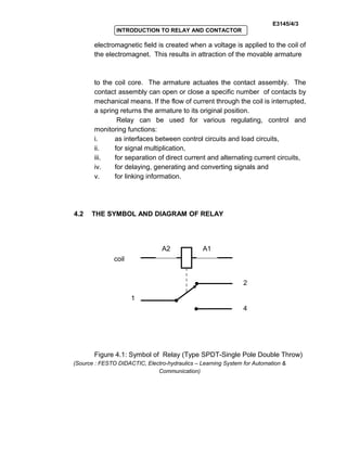
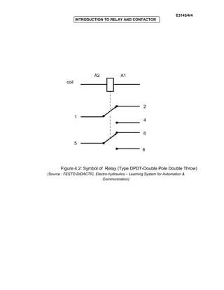
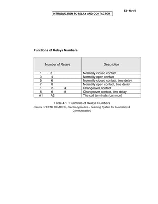
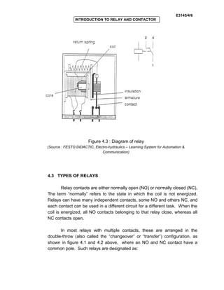
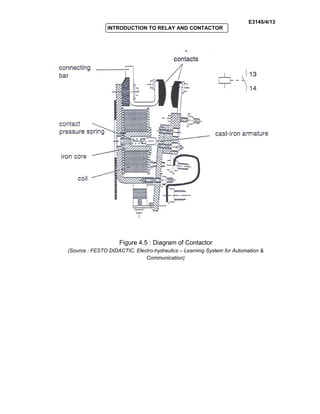
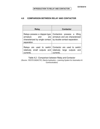
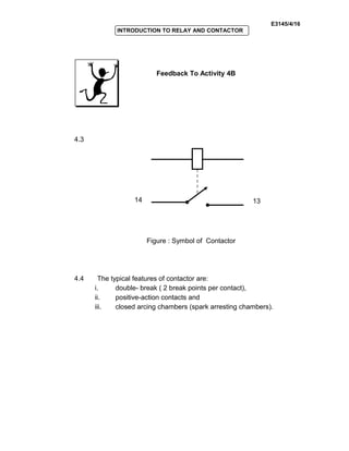
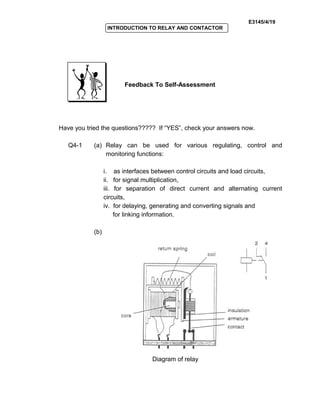
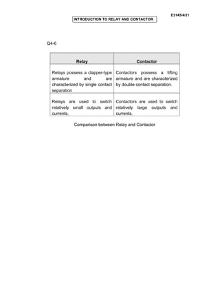
E3145/4/1
INTRODUCTION TO RELAY AND CONTACTOR
OBJECTIVES
General Objective : To know and to apply the concept of relay and
contactor.
Specific Objectives : At the end of the unit you will be able to :
 State the definition of relay.
 Draw the symbol and diagram of relay .
 Explain the type of relays.
 State the definition of contactor.
 Draw the symbol and diagram of contactor .
 Compare between relay and contactor.
UNIT4
E3145/4/2
INTRODUCTION TO RELAY AND CONTACTOR
4.0 EXPLANATION OF RELAY AND CONTACTOR
The representation of relays and contactor in the electrical
circuit diagram is identical, as is their operating principle.
i. Relays are used to switch relatively small output and currents;
ii. Contactors to switch relatively large output and currents.
4.1 DEFINITION OF RELAY
Relays are electromagnetically actuated switches. They
consist of a housing with electromagnet and movable contacts. An
INPUTINPUT
A relay is an
electromagnetic switch. A
small current flowing
through a coil in the relay
creates a magnetic field
that pulls one switch
contact against or away
from another.
E3145/4/3
INTRODUCTION TO RELAY AND CONTACTOR
electromagnetic field is created when a voltage is applied to the coil of
the electromagnet. This results in attraction of the movable armature
to the coil core. The armature actuates the contact assembly. The
contact assembly can open or close a specific number of contacts by
mechanical means. If the flow of current through the coil is interrupted,
a spring returns the armature to its original position.
Relay can be used for various regulating, control and
monitoring functions:
i. as interfaces between control circuits and load circuits,
ii. for signal multiplication,
iii. for separation of direct current and alternating current circuits,
iv. for delaying, generating and converting signals and
v. for linking information.
4.2 THE SYMBOL AND DIAGRAM OF RELAY
Figure 4.1: Symbol of Relay (Type SPDT-Single Pole Double Throw)
(Source : FESTO DIDACTIC, Electro-hydraulics – Learning System for Automation &
Communication)
1
2
4
A2 A1
coil
E3145/4/4
INTRODUCTION TO RELAY AND CONTACTOR
Figure 4.2: Symbol of Relay (Type DPDT-Double Pole Double Throw)
(Source : FESTO DIDACTIC, Electro-hydraulics – Learning System for Automation &
Communication)
1
5
2
4
6
8
coil
A2 A1
E3145/4/5
INTRODUCTION TO RELAY AND CONTACTOR
Functions of Relays Numbers
Number of Relays Description
1 2 Normally closed contact
3 4 Normally open contact
5 6 Normally closed contact, time delay
7 8 Normally open contact, time delay
1 2 4 Changeover contact
5 6 8 Changeover contact, time delay
A1 A2 The coil terminals (common)
Table 4.1 : Functions of Relays Numbers
(Source : FESTO DIDACTIC, Electro-hydraulics – Learning System for Automation &
Communication)
E3145/4/6
INTRODUCTION TO RELAY AND CONTACTOR
Figure 4.3 : Diagram of relay
(Source : FESTO DIDACTIC, Electro-hydraulics – Learning System for Automation &
Communication)
4.3 TYPES OF RELAYS
Relay contacts are either normally open (NO) or normally closed (NC),
The term “normally” refers to the state in which the coil is not energized.
Relays can have many independent contacts, some NO and others NC, and
each contact can be used in a different circuit for a different task. When the
coil is energized, all NO contacts belonging to that relay close, whereas all
NC contacts open.
In most relays with multiple contacts, these are arranged in the
double-throw (also called the “changeover” or “transfer”) configuration, as
shown in figure 4.1 and 4.2 above, where an NO and NC contact have a
common pole. Such relays are designated as:
E3145/4/7
INTRODUCTION TO RELAY AND CONTACTOR
i. SPDT (Single Pole Double Throw) refer to symbol figure 4.1
ii. DPDT (Double Pole Double Throw) refer to symbol figure 4.2
The word pole refers to the number of sets of contacts and the word
throw refers to the number of positions or combinations ( open or
close ) the contacts can have.
Refer to the two types of relays above (Figure 4.1), single pole (SP) is
a single contact (common) where a normally open (NO) and normally
closed (NC) relay have a common pole.
While a double pole (DP) means that each set of contacts has a
common terminal ( 1 and 5 ) connected to both an open and a closed
set of contacts (Figure 4.2). When the coil is energized, the circuit
between common and NO is closed, and when the coil is de-
energized the circuit between common and NC is closed.
E3145/4/8
INTRODUCTION TO RELAY AND CONTACTOR
Activity 4A
TEST YOUR UNDERSTANDING BEFORE YOU CONTINUE WITH THE
NEXT INPUT
!
4.1 Explain the definition of relay.
4.2 Draw the symbol of relay.
E3145/4/9
INTRODUCTION TO RELAY AND CONTACTOR
Feedback To Activity 4A
4.1 A relay is an electromagnetic switch. A small current flowing
through a coil in the relay creates a magnetic field that pulls one
switch contact against or away from another.
4.2
Symbol of Relay (Type SPDT-Single Pole Double Throw)
1
2
4
A2 A1
coil
E3145/4/10
INTRODUCTION TO RELAY AND CONTACTOR
Symbol of Relay (Type DPDT-Double Pole Double Throw)
1
5
2
4
6
8
coil
A2 A1
E3145/4/11
INTRODUCTION TO RELAY AND CONTACTOR
4.4 EXPLANATION OF CONTACTOR
Contactors work on the same basic principle as relays. The
typical features of contactor are:
i. double- break ( 2 break points per contact),
ii. positive-action contacts and
iii. closed arcing chambers (spark arresting chambers).
A contactor possesses several contact elements, normally
between 4 and 10. There are also different types of contactors with
various combinations of normally closed contacts, normally open
contacts, changeover contacts, delayed normally closed contacts etc.
The contacts are divided into main contact elements and auxiliary
contacts (control contacts)
i. Outputs of 4 – 30kW are switched via main contact
elements.
ii. The auxiliary contacts can be used to simultaneously
switch further control functions or logic operations.
iii. Contactors which only switch auxiliary contacts (control
contacts) are called contactor relays (control contactors).
iv. For the purpose of classification, contactors with main
contact elements for power switching are called power
contactors (main contactors).
INPUTINPUT
E3145/4/12
INTRODUCTION TO RELAY AND CONTACTOR
4.5 THE SYMBOL AND DIAGRAM OF CONTACTOR
Figure 4.4 : Symbol of Contactor.
(Source : FESTO DIDACTIC, Electro-hydraulics – Learning System for Automation &
Communication)
14 13
E3145/4/13
INTRODUCTION TO RELAY AND CONTACTOR
Figure 4.5 : Diagram of Contactor
(Source : FESTO DIDACTIC, Electro-hydraulics – Learning System for Automation &
Communication)
E3145/4/14
INTRODUCTION TO RELAY AND CONTACTOR
4.6 COMPARISON BETWEEN RELAY AND CONTACTOR
Relay Contactor
Relays possess a clapper-type
armature and are
characterized by single contact
separation
Contactors possess a lifting
armature and are characterized
by double contact separation.
Relays are used to switch
relatively small outputs and
currents.
Contactor are used to switch
relatively large outputs and
currents.
Table 4.2 : Comparison between Relay and Contactor
(Source : FESTO DIDACTIC, Electro-hydraulics – Learning System for Automation &
Communication)
E3145/4/15
INTRODUCTION TO RELAY AND CONTACTOR
Activity 4B
TEST YOUR UNDERSTANDING BEFORE YOU CONTINUE WITH THE
NEXT INPUT
!
4.3 Draw the symbol of contactor.
4.4 State the typical features of contactor.
E3145/4/16
INTRODUCTION TO RELAY AND CONTACTOR
Feedback To Activity 4B
4.3
Figure : Symbol of Contactor
4.4 The typical features of contactor are:
i. double- break ( 2 break points per contact),
ii. positive-action contacts and
iii. closed arcing chambers (spark arresting chambers).
14 13
E3145/4/17
INTRODUCTION TO RELAY AND CONTACTOR
KEY FACTS
1. (i) Relays possess a clapper-type armature and are
characterized by single contact separation.
(ii) Relays are used to switch relatively small outputs and
currents.
2. (i) Contactors possess a lifting armature and are characterized
by double contact separation.
(ii) Contactors are used to switch relatively large outputs and
currents
E3145/4/18
INTRODUCTION TO RELAY AND CONTACTOR
SELF-ASSESSMENT
You are approaching success. Try all the questions in this self-assessment
section and check your answers with those given in the Feedback on Self-
Assessment given on the next page. If you face any problems, discuss it
with your lecturer. Good luck.
Q4-1 (a) Identify the application of relay.
(b) Draw the diagram of relay.
(c) Explain the function of normally open (NO) and normally
closed (NC) relay contacts.
(d) State the strengths and weaknesses of relay.
Q4-2 (a) Give the definition of coil in contactor.
(b) Identify the comparison between relay and contactor.
E3145/4/19
INTRODUCTION TO RELAY AND CONTACTOR
Feedback To Self-Assessment
Have you tried the questions????? If “YES”, check your answers now.
Q4-1 (a) Relay can be used for various regulating, control and
monitoring functions:
i. as interfaces between control circuits and load circuits,
ii. for signal multiplication,
iii. for separation of direct current and alternating current
circuits,
iv. for delaying, generating and converting signals and
for linking information.
(b)
Diagram of relay
E3145/4/20
INTRODUCTION TO RELAY AND CONTACTOR
Q4-3 Relay contacts are either normally open (NO) or normally
closed (NC), The term “normally” refers to the state in which
the coil is not energized. Relays can have many independent
contacts, some NO and others NC, and each contact can be
used in a different circuit for a different task. When the coil is
energized, all NO contacts belonging to that relay close,
whereas all NC contacts open.
Q4-4
Strengths Weaknesses
Easy to change out Contact wear
Durable Moving parts (springs) limit live
expectancy from 1-3 million
cycles
Easy to test Require more power
Available with plug-in base
Miniature relays available
Immune to noise
The strengths and weaknesses of Relay
Q4-5 The coil is manufactured in a rectangular shape with two
square holes in it. This holes provide a space for the magnet
yoke to pro-armature move to the closed position.
E3145/4/21
INTRODUCTION TO RELAY AND CONTACTOR
Q4-6
Relay Contactor
Relays possess a clapper-type
armature and are
characterized by single contact
separation
Contactors possess a lifting
armature and are characterized
by double contact separation.
Relays are used to switch
relatively small outputs and
currents.
Contactors are used to switch
relatively large outputs and
currents.
Comparison between Relay and Contactor
E3145/4/22
INTRODUCTION TO RELAY AND CONTACTOR
E3145/4/23
INTRODUCTION TO RELAY AND CONTACTOR
E3145/4/24
INTRODUCTION TO RELAY AND CONTACTOR
E3145/4/25
INTRODUCTION TO RELAY AND CONTACTOR
.
E3145/4/26
INTRODUCTION TO RELAY AND CONTACTOR
E3145/4/27
INTRODUCTION TO RELAY AND CONTACTOR
E3145/4/28
INTRODUCTION TO RELAY AND CONTACTOR
E3145/4/29
INTRODUCTION TO RELAY AND CONTACTOR
E3145/4/30
INTRODUCTION TO RELAY AND CONTACTOR

Basic Control System unit4

  • 1.
    E3145/4/1 INTRODUCTION TO RELAYAND CONTACTOR INTRODUCTION TO RELAY AND CONTACTOR OBJECTIVES General Objective : To know and to apply the concept of relay and contactor. Specific Objectives : At the end of the unit you will be able to :  State the definition of relay.  Draw the symbol and diagram of relay .  Explain the type of relays.  State the definition of contactor.  Draw the symbol and diagram of contactor .  Compare between relay and contactor. UNIT4
  • 2.
    E3145/4/2 INTRODUCTION TO RELAYAND CONTACTOR 4.0 EXPLANATION OF RELAY AND CONTACTOR The representation of relays and contactor in the electrical circuit diagram is identical, as is their operating principle. i. Relays are used to switch relatively small output and currents; ii. Contactors to switch relatively large output and currents. 4.1 DEFINITION OF RELAY Relays are electromagnetically actuated switches. They consist of a housing with electromagnet and movable contacts. An INPUTINPUT A relay is an electromagnetic switch. A small current flowing through a coil in the relay creates a magnetic field that pulls one switch contact against or away from another.
  • 3.
    E3145/4/3 INTRODUCTION TO RELAYAND CONTACTOR electromagnetic field is created when a voltage is applied to the coil of the electromagnet. This results in attraction of the movable armature to the coil core. The armature actuates the contact assembly. The contact assembly can open or close a specific number of contacts by mechanical means. If the flow of current through the coil is interrupted, a spring returns the armature to its original position. Relay can be used for various regulating, control and monitoring functions: i. as interfaces between control circuits and load circuits, ii. for signal multiplication, iii. for separation of direct current and alternating current circuits, iv. for delaying, generating and converting signals and v. for linking information. 4.2 THE SYMBOL AND DIAGRAM OF RELAY Figure 4.1: Symbol of Relay (Type SPDT-Single Pole Double Throw) (Source : FESTO DIDACTIC, Electro-hydraulics – Learning System for Automation & Communication) 1 2 4 A2 A1 coil
  • 4.
    E3145/4/4 INTRODUCTION TO RELAYAND CONTACTOR Figure 4.2: Symbol of Relay (Type DPDT-Double Pole Double Throw) (Source : FESTO DIDACTIC, Electro-hydraulics – Learning System for Automation & Communication) 1 5 2 4 6 8 coil A2 A1
  • 5.
    E3145/4/5 INTRODUCTION TO RELAYAND CONTACTOR Functions of Relays Numbers Number of Relays Description 1 2 Normally closed contact 3 4 Normally open contact 5 6 Normally closed contact, time delay 7 8 Normally open contact, time delay 1 2 4 Changeover contact 5 6 8 Changeover contact, time delay A1 A2 The coil terminals (common) Table 4.1 : Functions of Relays Numbers (Source : FESTO DIDACTIC, Electro-hydraulics – Learning System for Automation & Communication)
  • 6.
    E3145/4/6 INTRODUCTION TO RELAYAND CONTACTOR Figure 4.3 : Diagram of relay (Source : FESTO DIDACTIC, Electro-hydraulics – Learning System for Automation & Communication) 4.3 TYPES OF RELAYS Relay contacts are either normally open (NO) or normally closed (NC), The term “normally” refers to the state in which the coil is not energized. Relays can have many independent contacts, some NO and others NC, and each contact can be used in a different circuit for a different task. When the coil is energized, all NO contacts belonging to that relay close, whereas all NC contacts open. In most relays with multiple contacts, these are arranged in the double-throw (also called the “changeover” or “transfer”) configuration, as shown in figure 4.1 and 4.2 above, where an NO and NC contact have a common pole. Such relays are designated as:
  • 7.
    E3145/4/7 INTRODUCTION TO RELAYAND CONTACTOR i. SPDT (Single Pole Double Throw) refer to symbol figure 4.1 ii. DPDT (Double Pole Double Throw) refer to symbol figure 4.2 The word pole refers to the number of sets of contacts and the word throw refers to the number of positions or combinations ( open or close ) the contacts can have. Refer to the two types of relays above (Figure 4.1), single pole (SP) is a single contact (common) where a normally open (NO) and normally closed (NC) relay have a common pole. While a double pole (DP) means that each set of contacts has a common terminal ( 1 and 5 ) connected to both an open and a closed set of contacts (Figure 4.2). When the coil is energized, the circuit between common and NO is closed, and when the coil is de- energized the circuit between common and NC is closed.
  • 8.
    E3145/4/8 INTRODUCTION TO RELAYAND CONTACTOR Activity 4A TEST YOUR UNDERSTANDING BEFORE YOU CONTINUE WITH THE NEXT INPUT
! 4.1 Explain the definition of relay. 4.2 Draw the symbol of relay.
  • 9.
    E3145/4/9 INTRODUCTION TO RELAYAND CONTACTOR Feedback To Activity 4A 4.1 A relay is an electromagnetic switch. A small current flowing through a coil in the relay creates a magnetic field that pulls one switch contact against or away from another. 4.2 Symbol of Relay (Type SPDT-Single Pole Double Throw) 1 2 4 A2 A1 coil
  • 10.
    E3145/4/10 INTRODUCTION TO RELAYAND CONTACTOR Symbol of Relay (Type DPDT-Double Pole Double Throw) 1 5 2 4 6 8 coil A2 A1
  • 11.
    E3145/4/11 INTRODUCTION TO RELAYAND CONTACTOR 4.4 EXPLANATION OF CONTACTOR Contactors work on the same basic principle as relays. The typical features of contactor are: i. double- break ( 2 break points per contact), ii. positive-action contacts and iii. closed arcing chambers (spark arresting chambers). A contactor possesses several contact elements, normally between 4 and 10. There are also different types of contactors with various combinations of normally closed contacts, normally open contacts, changeover contacts, delayed normally closed contacts etc. The contacts are divided into main contact elements and auxiliary contacts (control contacts) i. Outputs of 4 – 30kW are switched via main contact elements. ii. The auxiliary contacts can be used to simultaneously switch further control functions or logic operations. iii. Contactors which only switch auxiliary contacts (control contacts) are called contactor relays (control contactors). iv. For the purpose of classification, contactors with main contact elements for power switching are called power contactors (main contactors). INPUTINPUT
  • 12.
    E3145/4/12 INTRODUCTION TO RELAYAND CONTACTOR 4.5 THE SYMBOL AND DIAGRAM OF CONTACTOR Figure 4.4 : Symbol of Contactor. (Source : FESTO DIDACTIC, Electro-hydraulics – Learning System for Automation & Communication) 14 13
  • 13.
    E3145/4/13 INTRODUCTION TO RELAYAND CONTACTOR Figure 4.5 : Diagram of Contactor (Source : FESTO DIDACTIC, Electro-hydraulics – Learning System for Automation & Communication)
  • 14.
    E3145/4/14 INTRODUCTION TO RELAYAND CONTACTOR 4.6 COMPARISON BETWEEN RELAY AND CONTACTOR Relay Contactor Relays possess a clapper-type armature and are characterized by single contact separation Contactors possess a lifting armature and are characterized by double contact separation. Relays are used to switch relatively small outputs and currents. Contactor are used to switch relatively large outputs and currents. Table 4.2 : Comparison between Relay and Contactor (Source : FESTO DIDACTIC, Electro-hydraulics – Learning System for Automation & Communication)
  • 15.
    E3145/4/15 INTRODUCTION TO RELAYAND CONTACTOR Activity 4B TEST YOUR UNDERSTANDING BEFORE YOU CONTINUE WITH THE NEXT INPUT
! 4.3 Draw the symbol of contactor. 4.4 State the typical features of contactor.
  • 16.
    E3145/4/16 INTRODUCTION TO RELAYAND CONTACTOR Feedback To Activity 4B 4.3 Figure : Symbol of Contactor 4.4 The typical features of contactor are: i. double- break ( 2 break points per contact), ii. positive-action contacts and iii. closed arcing chambers (spark arresting chambers). 14 13
  • 17.
    E3145/4/17 INTRODUCTION TO RELAYAND CONTACTOR KEY FACTS 1. (i) Relays possess a clapper-type armature and are characterized by single contact separation. (ii) Relays are used to switch relatively small outputs and currents. 2. (i) Contactors possess a lifting armature and are characterized by double contact separation. (ii) Contactors are used to switch relatively large outputs and currents
  • 18.
    E3145/4/18 INTRODUCTION TO RELAYAND CONTACTOR SELF-ASSESSMENT You are approaching success. Try all the questions in this self-assessment section and check your answers with those given in the Feedback on Self- Assessment given on the next page. If you face any problems, discuss it with your lecturer. Good luck. Q4-1 (a) Identify the application of relay. (b) Draw the diagram of relay. (c) Explain the function of normally open (NO) and normally closed (NC) relay contacts. (d) State the strengths and weaknesses of relay. Q4-2 (a) Give the definition of coil in contactor. (b) Identify the comparison between relay and contactor.
  • 19.
    E3145/4/19 INTRODUCTION TO RELAYAND CONTACTOR Feedback To Self-Assessment Have you tried the questions????? If “YES”, check your answers now. Q4-1 (a) Relay can be used for various regulating, control and monitoring functions: i. as interfaces between control circuits and load circuits, ii. for signal multiplication, iii. for separation of direct current and alternating current circuits, iv. for delaying, generating and converting signals and for linking information. (b) Diagram of relay
  • 20.
    E3145/4/20 INTRODUCTION TO RELAYAND CONTACTOR Q4-3 Relay contacts are either normally open (NO) or normally closed (NC), The term “normally” refers to the state in which the coil is not energized. Relays can have many independent contacts, some NO and others NC, and each contact can be used in a different circuit for a different task. When the coil is energized, all NO contacts belonging to that relay close, whereas all NC contacts open. Q4-4 Strengths Weaknesses Easy to change out Contact wear Durable Moving parts (springs) limit live expectancy from 1-3 million cycles Easy to test Require more power Available with plug-in base Miniature relays available Immune to noise The strengths and weaknesses of Relay Q4-5 The coil is manufactured in a rectangular shape with two square holes in it. This holes provide a space for the magnet yoke to pro-armature move to the closed position.
  • 21.
    E3145/4/21 INTRODUCTION TO RELAYAND CONTACTOR Q4-6 Relay Contactor Relays possess a clapper-type armature and are characterized by single contact separation Contactors possess a lifting armature and are characterized by double contact separation. Relays are used to switch relatively small outputs and currents. Contactors are used to switch relatively large outputs and currents. Comparison between Relay and Contactor
  • 22.
  • 23.
  • 24.
  • 25.
  • 26.
  • 27.
  • 28.
  • 29.
  • 30.