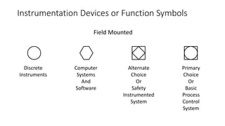
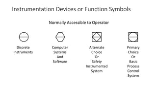
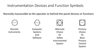
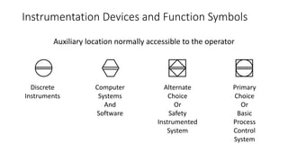
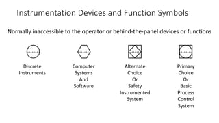
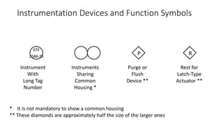
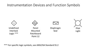
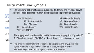
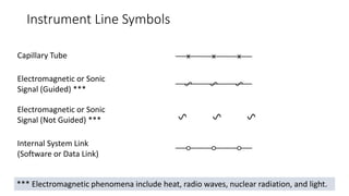
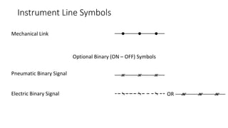
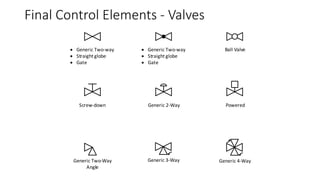
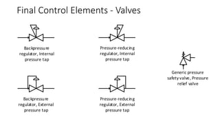
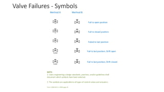
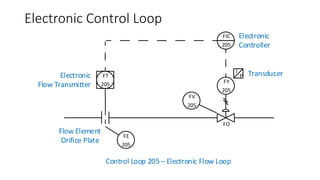
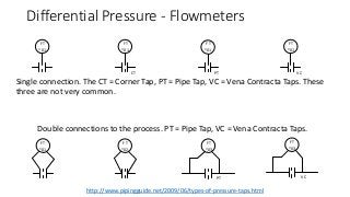
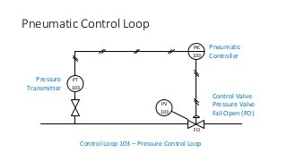
P&IDs and Symbols
A Primer for Students who have not taken EMEC125
EMEC130
P&ID – Widely Understood?
• P&ID is an acronym that is well understood to be the document used
to define a process.
• Definition:
• “A schematic diagram of the relationship between instruments, controllers,
piping, and system equipment.” (Kirk, Weedon, & Kirk, 2014, p. 23)
• P&IDs are a symbol based schematic language that once understood,
adds simplicity to the information being presented.
• They can also be confusing when a unique symbol appears.
• There is no real standard for what should be included on the drawing.
P&ID Acronym
• What does P&ID stand for?
• The letter meanings are not universal.
• ‘P’ could stand for “Piping” or it could stand for “Process”.
• ‘I’ could represent “Instrumentation” or represent “Instrument”.
• ‘D’ could mean “Drawing” or it could mean “Diagram”.
• Which ever is used, including those not listed, we are all talking about
the same document(s).
New ISA Standard – ISA-5.7 (Not Yet Released)
• As mentioned, “there is no universal, national, international or
international multi-discipline standard that covers the development
and content of P&IDs” (Meier & Meier, 2011, p. 27)
• The ISA is in the process of creating a standard that will be known as:
ISA-5.7 and is based on the Process Industries Practice (PIP) PIC 001.
• There is a standard that governs the symbols used on P&IDs. This
standard is ANSI/ISA-5.1-2009 Instrument Symbols and
Identifications. (See the introduction to this course)
What Comes From P&IDs?
• Instrument Lists or Index
• Documents specifications, acquisition and installation
• Motor Lists
• Size, horsepower, voltage
• Piping
• Line lists, sizes, service and purpose
• Tanks & Vessels
• Information about tanks and vessels
• All this information is used to lay out equipment, start specifying and
purchasing the necessary equipment.
Control Loop
• A collection of equipment consisting of at least three devices used to
automatically control a process or a part of a process
• The three most common devices is:
• A transmitter used to sense the PV and transmit the measured value to a
controller
• A controller used to compare the PV with a setpoint and generate a signal
based on that comparison
• A final control element that corrects the process
ANSI/ISA-5.1
• As stated earlier, the ANSI/ISA-5.1 is most often used by designers as
the standard for symbology. Following is a direct quote from the
standard:
“The symbols and identification methods contained in this standard have
evolved by the consensus method and are intended for wide application
throughout all industries. The symbols and designations are used as
conceptualizing aids, as design tools, as teaching devices, and as a concise
and specific means of communication in all types and kinds of technical,
engineering, procurement, construction, and maintenance documents and
not just in Piping and Instrumentation Diagrams.” (International Society of
Automation, 2009)
Identification Letters
• The ANSI/ISA-5.1-2009 Instrumentation Symbols and Identification
standard lists the preferred First Letter and Succeeding Letters.
• The standard also lists typical letter combinations.
• Keep these lists handy when reading or creating P&ID’s.
ISA Identification Letters
Instrument Identification (Tag Numbers)
• All instruments should have a metal, plastic or paper tag attached to
them that states an instrument identification number; known as a
“Tag Number”.
• There are several numbering schemes; however, the ISA standard,
ISA-RP-5.1 (1949) superseded by ANSI/ISA-5.1-1984 (R 1992)
superseded by ANSI/ISA-5.1-2009 is the most common.
• Tag numbers are an alpha-numeric code where the:
• Alpha portion should be no more than four upper case characters
• Numeric portion should be know more than four digits.
• The smaller the tag number, the better.
Typical Instrument Tag Number
• PDT 102 – Instrument Identification or Tag Number
• PDT – Function Identification
• P 102 – Loop Identification
• 102 – Loop Number
• P - First Letter
• DT - Succeeding Letters
• The most common identifiers are used for the most common process
variables in process control:
• F – Flow
• L – Level
• P – Pressure
• T - Temperature
Note: Hyphens are optional as separators
The Letter ‘X’ as a First Letter
• The letter ‘X’ as a first letter in a special case.
• The ANSI/ISA-5.1-2009 Standard states:
• “First-Letter or Succeeding-Letter for unclassified devices or functions (X), for
non-repetitive meanings that shall be defined outside tagging bubbles or by a
note in the document.” (International Society of Automation, 2009)
• A legend sheet and descriptive letters next to the bubble should
define the function letter ‘X’.
• Proper use is to not use the letter ‘X’ frequently and when used
should only be used once, or at least in a limited capacity
Symbology – Building Blocks
• Circles (Bubbles)
• Squares & Rectangles
• Triangles
• Half Circles
• Lines
PT
102
FIC
1
FT
FIC
2
Instrument Location Information
• ISA standard instrument symbols, location and accessibility
• Symbols are used to help identify the type of:
• Instrument
• Location
• Located in the field
• Not panel, console or cabinet mounted
• Visible at the field location
• Accessible to the operator
• Located in or on front of central or main console or panel
• Visible on front panel
• Location at rear of main or central panel
• Not accessible to the operator
Instrumentation Devices or Function Symbols
Field Mounted
Primary
Choice
Or
Basic
Process
Control
System
Alternate
Choice
Or
Safety
Instrumented
System
Computer
Systems
And
Software
Discrete
Instruments
Instrumentation Devices or Function Symbols
Normally Accessible to Operator
Primary
Choice
Or
Basic
Process
Control
System
Alternate
Choice
Or
Safety
Instrumented
System
Computer
Systems
And
Software
Discrete
Instruments
Instrumentation Devices and Function Symbols
Normally inaccessible to the operator or behind-the-panel devices or functions
Primary
Choice
Or
Basic
Process
Control
System
Alternate
Choice
Or
Safety
Instrumented
System
Computer
Systems
And
Software
Discrete
Instruments
Instrumentation Devices and Function Symbols
Auxiliary location normally accessible to the operator
Primary
Choice
Or
Basic
Process
Control
System
Alternate
Choice
Or
Safety
Instrumented
System
Computer
Systems
And
Software
Discrete
Instruments
Instrumentation Devices and Function Symbols
Normally inaccessible to the operator or behind-the-panel devices or functions
Primary
Choice
Or
Basic
Process
Control
System
Alternate
Choice
Or
Safety
Instrumented
System
Computer
Systems
And
Software
Discrete
Instruments
Instrumentation Devices and Function Symbols
6TE
2584-23
P R
Rest for
Latch-Type
Actuator **
Purge or
Flush
Device **
Instruments
Sharing
Common
Housing *
Instrument
With
Long Tag
Number
* It is not mandatory to show a common housing
** These diamonds are approximately half the size of the larger ones
Instrumentation Devices and Function Symbols
I 12
C
Pilot
Light
Diaphragm
Seal
Panel
Mounted
Patchboard
Point 12
Undefined
Interlock
Logic ***
*** For specific logic symbols, see ANSI/ISA Standard S5.2
Instrument Line Symbols
Instrument Supply
Or Connection to Process
Undefined Signal
ORElectrical Signal
Pneumatic Signal
Hydraulic Signal
Instrument Line Symbols
Electromagnetic or Sonic
Signal (Guided) ***
Internal System Link
(Software or Data Link)
Electromagnetic or Sonic
Signal (Not Guided) ***
Capillary Tube
*** Electromagnetic phenomena include heat, radio waves, nuclear radiation, and light.
Instrument Line Symbols
Optional Binary (ON – OFF) Symbols
Electric Binary Signal
Pneumatic Binary Signal
Mechanical Link
OR
Final Control Elements - Valves
 Generic Two-way
 Straight globe
 Gate
 Generic Two-way
 Straight globe
 Gate
Generic 2-WayScrew-down Powered
Ball Valve
Generic Two-Way
Angle
Generic 4-WayGeneric 3-Way
Backpressure
regulator, Internal
pressure tap
Pressure-reducing
regulator, Internal
pressure tap
Backpressure
regulator, External
pressure tap
Pressure-reducing
regulator, External
pressure tap
Generic pressure
safety valve, Pressure
relief valve
Final Control Elements - Valves
Positive Displacement
Turbine, Propeller Vortex Shedding
Variable AreaMagnetic 01
M
Magnetic 02
Standard Pitot Tube
Primary Flow Measurement - Flowmeters
FT
*01
FT
*01
FT
*01
FT
*01
FT
*01
FT
*02
FT
*03
PT
FT
*03
VC
CT PT VC
Differential Pressure - Flowmeters
Single connection. The CT = Corner Tap, PT = Pipe Tap, VC = Vena Contracta Taps. These
three are not very common.
Double connections to the process. PT = Pipe Tap, VC = Vena Contracta Taps.
http://www.pipingguide.net/2009/06/types-of-pressure-taps.html
Pneumatic Control Loop
PT
103
PIC
103
PV
103
FO
Pneumatic
Controller
Control Valve
Pressure Valve
Fail Open (FO)
Pressure
Transmitter
Control Loop 103 – Pressure Control Loop
Valve Failures
• Valves can fail in various positions
• Fail Open (FO)
• Fail Closed (FC)
• Fail Locked (FL)
• Fail in Last Position, Drift Open (FL/DO)
• Fail in Last Position, Drift Closed (FL/DC)
• Valves are shown on a P&ID by a shape that resembles a bow tie
• Actuators are shown with a line from the bow tie junction to a shape
such as a half circle, a square, a horizontal line, etc. (More on valve
symbols later in the chapter.
• The next slide shows symbols for valve failures
Valve Failures - Symbols
FO
FC
FL
FL/DO
FL/DC
Method A Method B
Fail to open position
Fail to closed position
Failed to last position
Fail to last position, Drift open
Fail to last position, Drift closed
NOTE:
1. Users engineering a design standards, practices, and/or guidelines shall
document which symbols have been selected.
2. The symbols are applicableto alltypes of control valves and actuators.
From: ANSI/ISA-5.1-2009 page 34
Electronic Control Loop
FO
Electronic
Controller
Electronic
Flow Transmitter
Control Loop 205 – Electronic Flow Loop
Flow Element
Orifice Plate
I
P Transducer
FV
205
FY
205
FIC
205
FT
205
FE
205

EMEC130 P&ID Symbol Primer

  • 1.
    P&IDs and Symbols APrimer for Students who have not taken EMEC125 EMEC130
  • 2.
    P&ID – WidelyUnderstood? • P&ID is an acronym that is well understood to be the document used to define a process. • Definition: • “A schematic diagram of the relationship between instruments, controllers, piping, and system equipment.” (Kirk, Weedon, & Kirk, 2014, p. 23) • P&IDs are a symbol based schematic language that once understood, adds simplicity to the information being presented. • They can also be confusing when a unique symbol appears. • There is no real standard for what should be included on the drawing.
  • 3.
    P&ID Acronym • Whatdoes P&ID stand for? • The letter meanings are not universal. • ‘P’ could stand for “Piping” or it could stand for “Process”. • ‘I’ could represent “Instrumentation” or represent “Instrument”. • ‘D’ could mean “Drawing” or it could mean “Diagram”. • Which ever is used, including those not listed, we are all talking about the same document(s).
  • 4.
    New ISA Standard– ISA-5.7 (Not Yet Released) • As mentioned, “there is no universal, national, international or international multi-discipline standard that covers the development and content of P&IDs” (Meier & Meier, 2011, p. 27) • The ISA is in the process of creating a standard that will be known as: ISA-5.7 and is based on the Process Industries Practice (PIP) PIC 001. • There is a standard that governs the symbols used on P&IDs. This standard is ANSI/ISA-5.1-2009 Instrument Symbols and Identifications. (See the introduction to this course)
  • 5.
    What Comes FromP&IDs? • Instrument Lists or Index • Documents specifications, acquisition and installation • Motor Lists • Size, horsepower, voltage • Piping • Line lists, sizes, service and purpose • Tanks & Vessels • Information about tanks and vessels • All this information is used to lay out equipment, start specifying and purchasing the necessary equipment.
  • 6.
    Control Loop • Acollection of equipment consisting of at least three devices used to automatically control a process or a part of a process • The three most common devices is: • A transmitter used to sense the PV and transmit the measured value to a controller • A controller used to compare the PV with a setpoint and generate a signal based on that comparison • A final control element that corrects the process
  • 7.
    ANSI/ISA-5.1 • As statedearlier, the ANSI/ISA-5.1 is most often used by designers as the standard for symbology. Following is a direct quote from the standard: “The symbols and identification methods contained in this standard have evolved by the consensus method and are intended for wide application throughout all industries. The symbols and designations are used as conceptualizing aids, as design tools, as teaching devices, and as a concise and specific means of communication in all types and kinds of technical, engineering, procurement, construction, and maintenance documents and not just in Piping and Instrumentation Diagrams.” (International Society of Automation, 2009)
  • 8.
    Identification Letters • TheANSI/ISA-5.1-2009 Instrumentation Symbols and Identification standard lists the preferred First Letter and Succeeding Letters. • The standard also lists typical letter combinations. • Keep these lists handy when reading or creating P&ID’s.
  • 9.
  • 10.
    Instrument Identification (TagNumbers) • All instruments should have a metal, plastic or paper tag attached to them that states an instrument identification number; known as a “Tag Number”. • There are several numbering schemes; however, the ISA standard, ISA-RP-5.1 (1949) superseded by ANSI/ISA-5.1-1984 (R 1992) superseded by ANSI/ISA-5.1-2009 is the most common. • Tag numbers are an alpha-numeric code where the: • Alpha portion should be no more than four upper case characters • Numeric portion should be know more than four digits. • The smaller the tag number, the better.
  • 11.
    Typical Instrument TagNumber • PDT 102 – Instrument Identification or Tag Number • PDT – Function Identification • P 102 – Loop Identification • 102 – Loop Number • P - First Letter • DT - Succeeding Letters • The most common identifiers are used for the most common process variables in process control: • F – Flow • L – Level • P – Pressure • T - Temperature Note: Hyphens are optional as separators
  • 12.
    The Letter ‘X’as a First Letter • The letter ‘X’ as a first letter in a special case. • The ANSI/ISA-5.1-2009 Standard states: • “First-Letter or Succeeding-Letter for unclassified devices or functions (X), for non-repetitive meanings that shall be defined outside tagging bubbles or by a note in the document.” (International Society of Automation, 2009) • A legend sheet and descriptive letters next to the bubble should define the function letter ‘X’. • Proper use is to not use the letter ‘X’ frequently and when used should only be used once, or at least in a limited capacity
  • 13.
    Symbology – BuildingBlocks • Circles (Bubbles) • Squares & Rectangles • Triangles • Half Circles • Lines PT 102 FIC 1 FT FIC 2
  • 14.
    Instrument Location Information •ISA standard instrument symbols, location and accessibility • Symbols are used to help identify the type of: • Instrument • Location • Located in the field • Not panel, console or cabinet mounted • Visible at the field location • Accessible to the operator • Located in or on front of central or main console or panel • Visible on front panel • Location at rear of main or central panel • Not accessible to the operator
  • 15.
    Instrumentation Devices orFunction Symbols Field Mounted Primary Choice Or Basic Process Control System Alternate Choice Or Safety Instrumented System Computer Systems And Software Discrete Instruments
  • 16.
    Instrumentation Devices orFunction Symbols Normally Accessible to Operator Primary Choice Or Basic Process Control System Alternate Choice Or Safety Instrumented System Computer Systems And Software Discrete Instruments
  • 17.
    Instrumentation Devices andFunction Symbols Normally inaccessible to the operator or behind-the-panel devices or functions Primary Choice Or Basic Process Control System Alternate Choice Or Safety Instrumented System Computer Systems And Software Discrete Instruments
  • 18.
    Instrumentation Devices andFunction Symbols Auxiliary location normally accessible to the operator Primary Choice Or Basic Process Control System Alternate Choice Or Safety Instrumented System Computer Systems And Software Discrete Instruments
  • 19.
    Instrumentation Devices andFunction Symbols Normally inaccessible to the operator or behind-the-panel devices or functions Primary Choice Or Basic Process Control System Alternate Choice Or Safety Instrumented System Computer Systems And Software Discrete Instruments
  • 20.
    Instrumentation Devices andFunction Symbols 6TE 2584-23 P R Rest for Latch-Type Actuator ** Purge or Flush Device ** Instruments Sharing Common Housing * Instrument With Long Tag Number * It is not mandatory to show a common housing ** These diamonds are approximately half the size of the larger ones
  • 21.
    Instrumentation Devices andFunction Symbols I 12 C Pilot Light Diaphragm Seal Panel Mounted Patchboard Point 12 Undefined Interlock Logic *** *** For specific logic symbols, see ANSI/ISA Standard S5.2
  • 22.
    Instrument Line Symbols InstrumentSupply Or Connection to Process Undefined Signal ORElectrical Signal Pneumatic Signal Hydraulic Signal
  • 23.
    Instrument Line Symbols Electromagneticor Sonic Signal (Guided) *** Internal System Link (Software or Data Link) Electromagnetic or Sonic Signal (Not Guided) *** Capillary Tube *** Electromagnetic phenomena include heat, radio waves, nuclear radiation, and light.
  • 24.
    Instrument Line Symbols OptionalBinary (ON – OFF) Symbols Electric Binary Signal Pneumatic Binary Signal Mechanical Link OR
  • 25.
    Final Control Elements- Valves  Generic Two-way  Straight globe  Gate  Generic Two-way  Straight globe  Gate Generic 2-WayScrew-down Powered Ball Valve Generic Two-Way Angle Generic 4-WayGeneric 3-Way
  • 26.
    Backpressure regulator, Internal pressure tap Pressure-reducing regulator,Internal pressure tap Backpressure regulator, External pressure tap Pressure-reducing regulator, External pressure tap Generic pressure safety valve, Pressure relief valve Final Control Elements - Valves
  • 27.
    Positive Displacement Turbine, PropellerVortex Shedding Variable AreaMagnetic 01 M Magnetic 02 Standard Pitot Tube Primary Flow Measurement - Flowmeters
  • 28.
    FT *01 FT *01 FT *01 FT *01 FT *01 FT *02 FT *03 PT FT *03 VC CT PT VC DifferentialPressure - Flowmeters Single connection. The CT = Corner Tap, PT = Pipe Tap, VC = Vena Contracta Taps. These three are not very common. Double connections to the process. PT = Pipe Tap, VC = Vena Contracta Taps. http://www.pipingguide.net/2009/06/types-of-pressure-taps.html
  • 29.
    Pneumatic Control Loop PT 103 PIC 103 PV 103 FO Pneumatic Controller ControlValve Pressure Valve Fail Open (FO) Pressure Transmitter Control Loop 103 – Pressure Control Loop
  • 30.
    Valve Failures • Valvescan fail in various positions • Fail Open (FO) • Fail Closed (FC) • Fail Locked (FL) • Fail in Last Position, Drift Open (FL/DO) • Fail in Last Position, Drift Closed (FL/DC) • Valves are shown on a P&ID by a shape that resembles a bow tie • Actuators are shown with a line from the bow tie junction to a shape such as a half circle, a square, a horizontal line, etc. (More on valve symbols later in the chapter. • The next slide shows symbols for valve failures
  • 31.
    Valve Failures -Symbols FO FC FL FL/DO FL/DC Method A Method B Fail to open position Fail to closed position Failed to last position Fail to last position, Drift open Fail to last position, Drift closed NOTE: 1. Users engineering a design standards, practices, and/or guidelines shall document which symbols have been selected. 2. The symbols are applicableto alltypes of control valves and actuators. From: ANSI/ISA-5.1-2009 page 34
  • 32.
    Electronic Control Loop FO Electronic Controller Electronic FlowTransmitter Control Loop 205 – Electronic Flow Loop Flow Element Orifice Plate I P Transducer FV 205 FY 205 FIC 205 FT 205 FE 205

Editor's Notes

  • #3 P&IDs are the documents that technicians will use when troubleshooting and/or repairing instrumentation. The symbols must be understood and are defined by the ANSI/ISA-5.1-2009 Standard; however, there is no real standard that specifies how much information and what type of information should be on these drawings. This can cause confusion when a technician is trying to decipher the meaning of a unique symbol that the designer included. As a designer, if a unique symbol is to be used there should be a note and/or a key on the drawing stating what the symbol represents and its function.
  • #4 Discuss the different meanings of the letters in P&ID.
  • #5 A discussion should be held about how not all P&IDs use common symbols from company to company and even within the same company. Discuss how, as drawings are updated over the years by various people, different symbols can be used for the same thing on different drawings within a drawing package. Also introduce the concept of loop numbering and loop numbering schemes. Do not talk about these schemes in detail, that will come later; however, mention that the ISA-5.1 lists nine different loop numbering schemes and some of them “are parallel - a duplicated numerical sequence for each loop variable. Others schemes are serial, a single numbering sequence for all loop variables.” (Meier & Meier, 2011, p. 29). There will be much more about symbols and loop numbering later in this chapter.
  • #6 Discuss what information is taken from P&IDs and how it can be used. If an actual P&ID drawing is available, show parts of the drawing that identify some or all of the items listed on this slide.
  • #7 Discuss the basics of a control loop. Mentions some of the more standard signals such as: 4-20mA 3-15 psig (pounds per square inch gauge) 6-30 psig 1-5VDC 10-50mA 0-10VDC -10 to 10VDC The next slide contains a simple control loop
  • #8 Discuss the standard and why it is important to follow the standard whenever possible.
  • #9 Click the hyperlink to display a PDF for the ANSI/ISA-5.1-2009 Standard list of Identification Letters. The Standard Identification Letters are on Page 30 of the standard, with notes about the table in Section 4.2 on Page 25 to 29. The Allowable Succeeding Letter Combinations are on Page 106 to 108 of the standard Discuss some examples such as those on page 42 in the textbook.
  • #12 Discuss the use of Letters and numbers and some generic variations. Then proceed to the next slide where there will be a link to the Identification Letters from the ANSI/ISA-5.1 Standard. PDT represents a Pressure Differential Transmitter
  • #13 Discuss the use of the Unclassified letter ‘X’. A good description can be found on page 39 & 40 in the Meier textbook.
  • #14 Discuss the use of the basic geometric shapes as per chapter 02 in the textbook. Students will most likely not know what most of the instruments are as of yet, nor will they have a good understand of the tagging and identifiers; however, provide a brief introduction to them, with much more to come in this and the next several chapters, and relate them to as many instruments on the lab trainers as time permits.
  • #15 Discuss the size of the graphical symbols used to create documents. This information is from: McAvinew, T., & Mulley, R. (2004). Control System Documentation Applying Symbols and Identification (2nd ed.). Research Triangle Park, North Carolina, USA: International Society of Automation. You should explain paper sizes A, B, C, D and E. Most of today’s students have never heard of these paper sizes.
  • #16 Briefly review the fact that all devices on a P&ID have a unique identification using letters and numbers. The next slide starts a discussion on series and parallel numbering
  • #17 Discuss the serial number method and point the students to the ANSI/ISA-5.1-2009 standard for more information. Serial is the most common method used for numbering; however, in very large process plants the numbers could easily go to four digits and many people are not comfortable with going being three digits. In large process plants the parallel numbering method would make more sense. Click the link on the slide to display a simple example of Serial Numbering
  • #18 Discuss the parallel number method and point the students to the ANSI/ISA-5.1-2009 standard for more information. Click the link on the slide to display a simple example of Parallel Numbering
  • #19 Review the various instrument mounting locations with students before proceeding to the next slides that show the symbols.
  • #20 Discuss the symbols on the next several slides Located in field Not panel, console or cabinet mounted Visible at the field location Accessible to the operator Review the table found on page 46 of the textbook and/or Table 5.1.1 on page 36 of the ANSI/ISA-5.1-2009 Standard
  • #21 Discuss these symbols Located in or on front of main or central console or panel Visible on the front of panel or on video display Normally accessible to the operator at the front console or panel Review the table found on page 46 of the textbook and/or Table 5.1.1 on page 36 of the ANSI/ISA-5.1-2009 Standard
  • #22 Discuss these symbols Located in the rear of the main or central panel Located in cabinet behind the panel Not visible on the front of the panel or on a video display Not normally accessible by the operator at the console or panel Review the table found on page 46 of the textbook and/or Table 5.1.1 on page 36 of the ANSI/ISA-5.1-2009 Standard
  • #23 Discuss these symbols Located in or on front of secondary or local console or panel Visible on the front panel or on a video display Normally accessible to the operator at the front console or panel Review the table found on page 46 of the textbook and/or Table 5.1.1 on page 36 of the ANSI/ISA-5.1-2009 Standard
  • #24 Discuss these symbols Located in the rear of the secondary or local panel Located in a field cabinet Not visible on the front of the panel or on a video display Not normally accessible to the operator at the console or the panel Review the table found on page 46 of the textbook and/or Table 5.1.1 on page 36 of the ANSI/ISA-5.1-2009 Standard
  • #25 The next two slide are a sample of additional symbols. Discuss some of the other symbols that are not referenced in the textbook but can be found on page 37 in Table 5.1.2 and on page 38 in Table 5.2.1 in the ANSI/ISA-5.1-2009 Standard
  • #26 Discuss some of the other symbols that are not referenced in the textbook but can be found on page 37 in Table 5.1.2 and on page 38 in Table 5.2.1 in the ANSI/ISA-5.1-2009 Standard
  • #27 Discuss the line types on the next several slides as found in the textbook in Table 2-13 on pages 48 & 49 and in Table 5.3.2 on pages 46 & 47 in the ANSI/ISA-5.1-2009 Standard. Click the slide to display the note for the single asterisk. Click the slide to return to the line types. Click the slide to display the note for the two asterisks. Click the slide to return to the line types. Click the slide to advance.
  • #28 Continue discussing line symbols
  • #29 Continue discussing line symbols
  • #30 Students will not know the different types of valves at this time. Point out that valves are simply a bow-tie symbol with add-ons that make the valve representative of what type of valve it is. Use the valves in the lab to demonstrate what they physically look like. There might not be a sample of all the valve types. Refer the students to Pages 48 through 55 of the ANSI/ISA-5.1-2009 Standard for more final control elements. The next slide shows some pressure relief valve symbols.
  • #31 Students will not know the different types of valves at this time. Point out that valves are simply a bow-tie symbol with add-ons that make the valve representative of what type of valve it is. Use the valves in the lab to demonstrate what they physically look like. There might not be a sample of all the valve types. Refer the students to Pages 48 through 55 of the ANSI/ISA-5.1-2009 Standard for more final control elements.
  • #32 Flow is a common measurement that is made in process control. There are many different types of flowmeters and methods of measuring flow. Shown on this slide are just a few. As before, the students will not have a knowledge of flow and flowmeters. Use the lab equipment when possible to show the physical device(s). The next slide is from the textbook and shows the P&ID for various methods of measuring flow by using differential pressure.
  • #33 Students will not know about differential flow at this time. Give a brief explanation of what an orifice plate flowmeter is and how, by measuring the pressure on either side, (differential pressure), a value for flow can be achieved. For more information on the types of taps used in orifice plate flowmeters, visit this website: http://www.pipingguide.net/2009/06/types-of-pressure-taps.html There will much more on all of these and other processes and measurements in upcoming course work.
  • #34 Review this simple pressure control loop. Identify the transmitter measuring the pressure. There is a generic valve that can be used to remove the pressure transmitter from the loop. Identify the PIC as a pressure indicator controller that supplies a 3-15 psig out to control the valve. Identify the pressure control valve, PV, as a Fail Open (FO). Identify the symbols for major pipes, and pneumatic signals Students will not know much of anything about this diagram; however, after explaining to them what it is and how it functions, poll the class as it if there is anything missing? (See page 35 in the text). Items that could be included that are not: Air sets Setpoints Root drive Control valve size Valve positioner Controller location
  • #35 Discuss the failure modes that can occur in valves with some examples. Such as, a drain valve on a vessel filled with toxic material would want to fail closed so that none of the toxic materials will escape the vessel. Also mention that the symbols vary on the type of valve and how it is controlled and that valves will be covered later in the chapter.
  • #36 Click the image to enlarge. A PDF file will open. Discuss the standard symbols used for valve failure identification. The notes come from the ANSI/ISA-5.1-2009 Standard page 34
  • #37 Review this simple Electronic control loop. Identify the instruments, pipes and line types. Identify the control valve, FV, as a Fail Open (FO). Students will not know much of anything about this diagram; however, explaining to them what it is and how it functions. (See page 36 in the text). FT – Flow Transmitter FE – Flow Sensor Primary Element FIC – Flow Indicator Controller FY – Flow Transducer I/P FV – Flow Valve