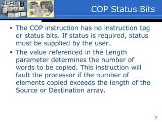
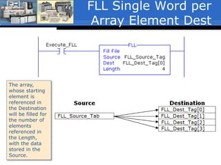
![4
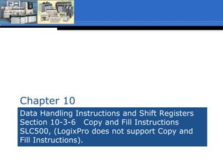
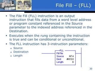
Source
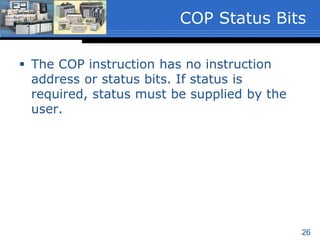
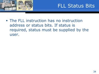
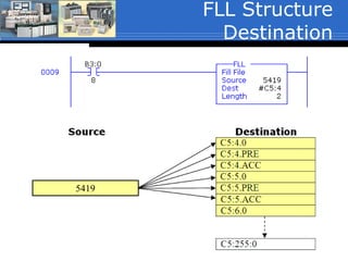
A word level tag that contains the data to be
copied.
Must be an array with at least one word; ex.
ArrayName[0]. (ArrayName[x], where ‘x’ is the
starting element of the array).
The word level tag with array element
reference is the starting word of the array to
be copied.
Data type of SINT, INT, DINT, REAL or
Structure.
COP Instruction
Parameters (1 of 3)](https://image.slidesharecdn.com/02copyfilefillsp16-160118220132/85/02-copy-file_fill_sp16-4-320.jpg)
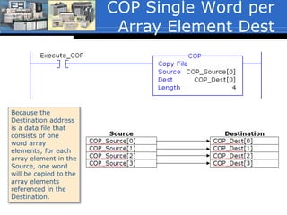
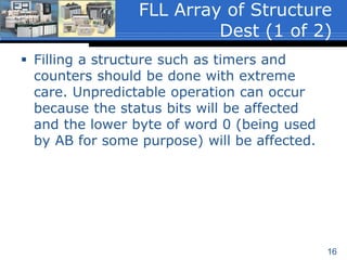
![5
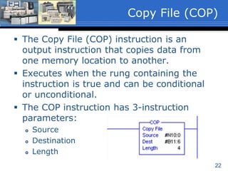
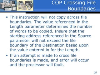
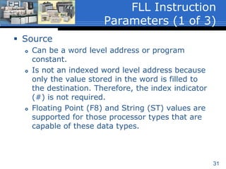
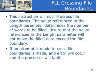
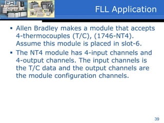
Destination
A word level tag with array element reference
that is the starting word of the array to which
the Source data is to be copied.
Must be an array with at least the same number
of elements as the array referenced in the
Source; ex. ArrayDest[0].
The instruction will overwrite any data that is
already stored in the Destination without
notification.
Data type of SINT, INT, DINT, REAL or
Structure.
COP Instruction
Parameters (2 of 3)](https://image.slidesharecdn.com/02copyfilefillsp16-160118220132/85/02-copy-file_fill_sp16-5-320.jpg)
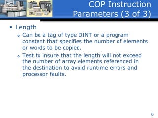
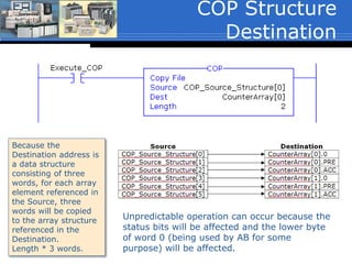
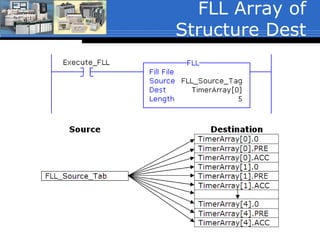
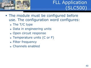
![17
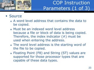
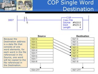
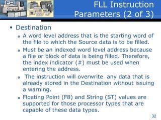
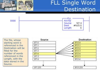
The example shown on the next slide will fill
five timer structures starting at TimerArray[0]
with the value stored in the Source tag
FLL_Source_Tag:
TimerArray[0].0 (the status bit word) =
FLL_Source_Tag
TimerArray[0].PRE = FLL_Source_Tag
TimerArray[0].ACC = FLL_Source_Tag
Through
TimerArray[4].0 (the status bit word) =
FLL_Source_Tag
TimerArray[4].PRE = FLL_Source_Tag
TimerArray[4].ACC = FLL_Source_Tag
FLL Array of Structure
Dest (2 of 2)](https://image.slidesharecdn.com/02copyfilefillsp16-160118220132/85/02-copy-file_fill_sp16-17-320.jpg)
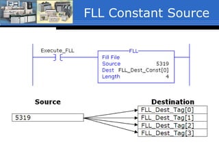
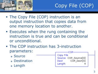
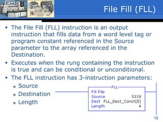
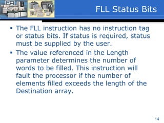
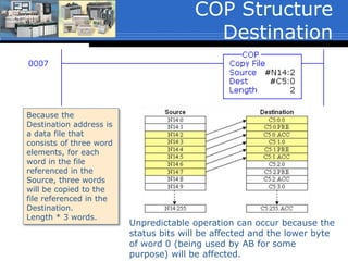
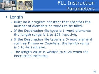
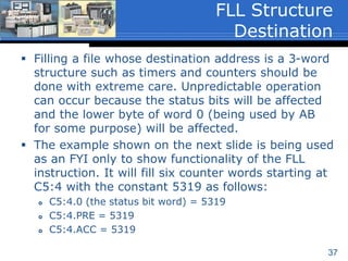
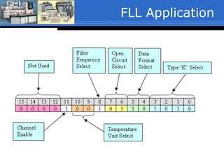
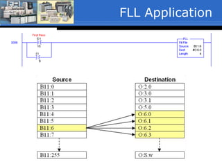
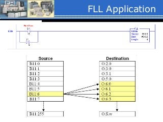
![Recipe Application
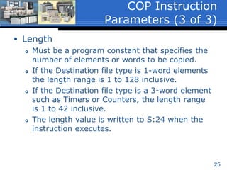
This example copies 1-of-4 user
selected recipes to the batch
parameters of a batch process.
The COP instruction shown will copy
the content of 4-words from a two-
dimensional array referenced in the
source, to a one-dimensional array in
the destination. (The COP will be
discussed in the next unit).
The source tag is referencing a two-
dimensional array:
Recipe[RecipeNumber, 0]. Note that
the first dimension of the array is a
tag. This tag stores the value of the
recipe number selected by a user and
is used to point to 1-of-4 of the
recipes.
If the user selects recipe number 2, the
data stored in Recipe[2,0],
Recipe[2,1], Recipe[2,2] and
Recipe[2,3] will be copied to:
BatchRecipe[0] through BatchRecipe[3]
respectively.
0
1
2
3](https://image.slidesharecdn.com/02copyfilefillsp16-160118220132/85/02-copy-file_fill_sp16-20-320.jpg)


The document discusses the Copy File (COP) and File Fill (FLL) instructions in Allen-Bradley PLCs and SLC500 controllers. The COP instruction copies data from a source location to a destination location, specifying the source, destination, and length. The FLL instruction fills a destination location with a source value, also specifying the source, destination, and length. Both instructions can copy/fill arrays and structures like timers but require care when filling status-containing structures. An example application uses COP and FLL to copy and configure a thermocouple module's input/output channels.