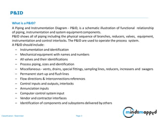
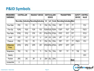
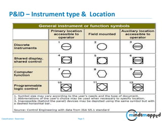
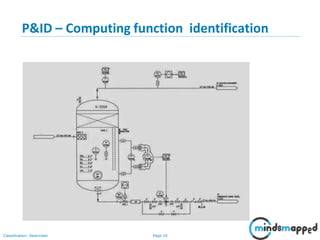
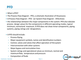
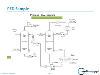
Industrial Automation Training
P&ID
Page 2Classification: Restricted
Agenda
• P&ID
• P&ID Symbols
• P&ID – Instrument type & Location
• P&ID – Piping & instrument connection symbols
• P&ID – Valves & its identification
• P&ID – Tagging Philosophy & Interconnection details
• P&ID – Computing function identification
• PFD
• PFD Sample
Page 3Classification: Restricted
P&ID
What is a P&ID?
A Piping and Instrumentation Diagram - P&ID, is a schematic illustration of functional relationship
of piping, instrumentation and system equipmentcomponents.
P&ID shows all of piping including the physical sequence of branches, reducers, valves, equipment,
instrumentation and control interlocks. The P&ID are used to operate the process system.
A P&ID should include:
– Instrumentation and identification
– Mechanical equipment with names and numbers
– All valves and their identifications
– Process piping, sizes and identification
– Miscellaneous - vents, drains, special fittings, sampling lines, reducers, increasers and swagers
– Permanent start-up and flushlines
– Flow directions & Interconnectionsreferences
– Control inputs and outputs, interlocks
– Annunciation inputs
– Computer control system input
– Vendor and contractor interfaces
– Identification of components and subsystems delivered byothers
Page 4Classification: Restricted
P&ID Symbols
Page 5Classification: Restricted
P&ID – Instrument type & Location
Page 6Classification: Restricted
P&ID – Piping & instrument connection symbols
Page 7Classification: Restricted
P&ID – Valves & its identification
Page 8Classification: Restricted
P&ID – Tagging Philosophy & Interconnection details
Page 9Classification: Restricted
P&ID – Computing function identification
Page 10Classification: Restricted
P&ID – Computing function identification
Page 11Classification: Restricted
PFD
• What is PFD?
• The Process Flow Diagram - PFD, a schematic illustration of theprocess
• A Process Flow Diagram - PFD - (or System Flow Diagram - SFD)shows
• the relationships between the major components in the system. PFD also tabulate
process design values for the components in different operating modes, typical
minimum, normaland maximum. A PFD does not show minor components, piping
systems, piping ratings and designations.
• A PFD should include:
– Process Piping
– Major equipment symbols, names and identificationnumbers
– Control, valves and valves that affect operation of thesystem
– Interconnection with other systems
– Major bypass and recirculation lines
– System ratings and operational values as minimum, normal and
maximumflow, temperature and pressure
– Composition of fluids
Page 12Classification: Restricted
PFD Sample
Page 13Classification: Restricted
Q&A
Page 14Classification: Restricted
Thank You!

P and Id

  • 1.
  • 2.
    Page 2Classification: Restricted Agenda •P&ID • P&ID Symbols • P&ID – Instrument type & Location • P&ID – Piping & instrument connection symbols • P&ID – Valves & its identification • P&ID – Tagging Philosophy & Interconnection details • P&ID – Computing function identification • PFD • PFD Sample
  • 3.
    Page 3Classification: Restricted P&ID Whatis a P&ID? A Piping and Instrumentation Diagram - P&ID, is a schematic illustration of functional relationship of piping, instrumentation and system equipmentcomponents. P&ID shows all of piping including the physical sequence of branches, reducers, valves, equipment, instrumentation and control interlocks. The P&ID are used to operate the process system. A P&ID should include: – Instrumentation and identification – Mechanical equipment with names and numbers – All valves and their identifications – Process piping, sizes and identification – Miscellaneous - vents, drains, special fittings, sampling lines, reducers, increasers and swagers – Permanent start-up and flushlines – Flow directions & Interconnectionsreferences – Control inputs and outputs, interlocks – Annunciation inputs – Computer control system input – Vendor and contractor interfaces – Identification of components and subsystems delivered byothers
  • 4.
  • 5.
    Page 5Classification: Restricted P&ID– Instrument type & Location
  • 6.
    Page 6Classification: Restricted P&ID– Piping & instrument connection symbols
  • 7.
    Page 7Classification: Restricted P&ID– Valves & its identification
  • 8.
    Page 8Classification: Restricted P&ID– Tagging Philosophy & Interconnection details
  • 9.
    Page 9Classification: Restricted P&ID– Computing function identification
  • 10.
    Page 10Classification: Restricted P&ID– Computing function identification
  • 11.
    Page 11Classification: Restricted PFD •What is PFD? • The Process Flow Diagram - PFD, a schematic illustration of theprocess • A Process Flow Diagram - PFD - (or System Flow Diagram - SFD)shows • the relationships between the major components in the system. PFD also tabulate process design values for the components in different operating modes, typical minimum, normaland maximum. A PFD does not show minor components, piping systems, piping ratings and designations. • A PFD should include: – Process Piping – Major equipment symbols, names and identificationnumbers – Control, valves and valves that affect operation of thesystem – Interconnection with other systems – Major bypass and recirculation lines – System ratings and operational values as minimum, normal and maximumflow, temperature and pressure – Composition of fluids
  • 12.
  • 13.
  • 14.