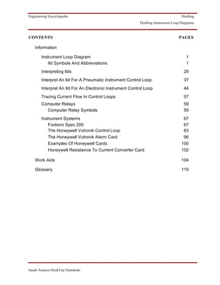
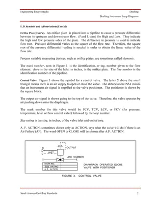
The document provides information on drafting instrument loop diagrams (ILDs) including common symbols and abbreviations used in ILDs. Some key symbols described are for orifice plates, control valves, electrical switches, lamps/lights, and different types of lines. ILDs provide detailed information about instrument control loops and are commonly used in drawings at Saudi Aramco.
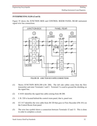
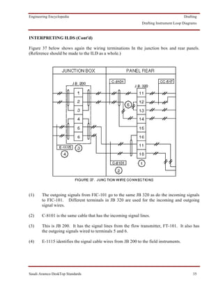
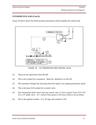
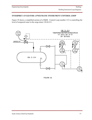
![Engineering Encyclopedia Drafting
Drafting Instrument Loop Diagrams
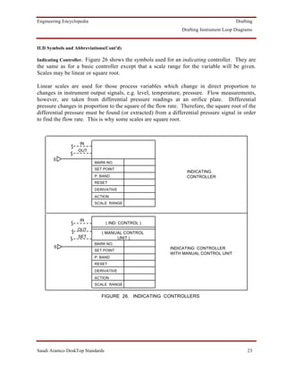
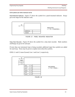
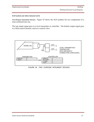
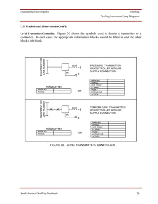
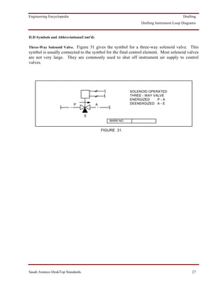
ILD Symbols and Abbreviations(Cont'd)
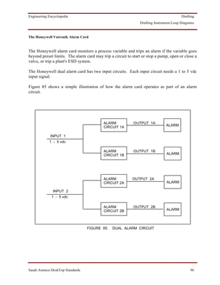
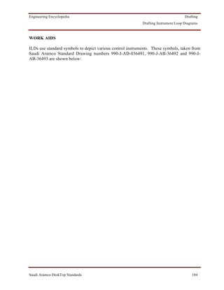
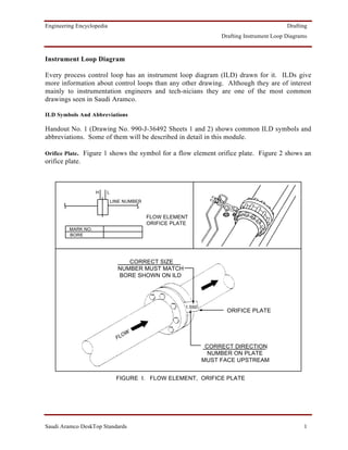
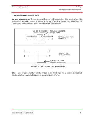
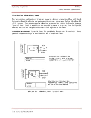
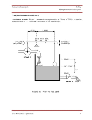
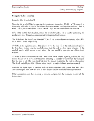
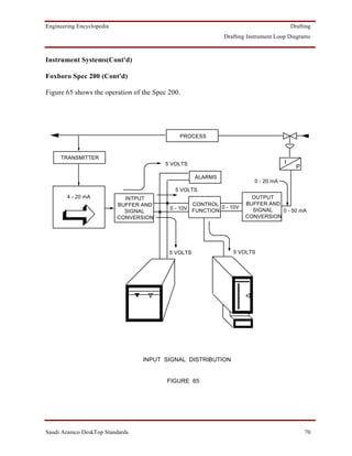
Pressure and Flow Transmitters. Figure 19 shows two kinds of transmitters, one for pressure and
one for flow. The difference is in the connection to the process. Pressure measurement
requires only one connection. Flow measurement requires two connections; one for the high
pressure side of the orifice plate, and one for the low side.
EQUIPMENT OR
LINE NUMBER
RED
+
_
GREY
PRESSURE TRANSMITTER
MARK NO.
RANGE
OUT
IN
S
FLOW TRANSMITTER WITH AIR
MARK NO. SUPPLY CONNECTION
RANGE
FIGURE 19
Note that the flow transmitter has two input lines (on the left). This is because the flow
transmitter is using differential pressure.
Range will show the calibrated range of each transmitter. Examples would be:
• 0 - 100 psi (for pressure transmitter)
• 0 - 100" W.C. (inches water column) - [for flow transmitter]
Saudi Aramco DeskTop Standards 15](https://image.slidesharecdn.com/ild-120401080742-phpapp02/85/ARMACO-STANDARD-17-320.jpg)


![Engineering Encyclopedia Drafting
Drafting Instrument Loop Diagrams
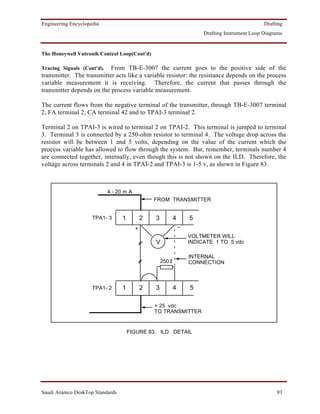
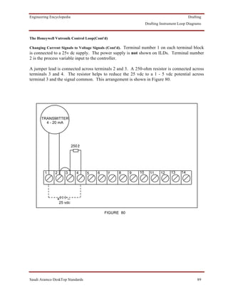
The Honeywell Vutronik Control Loop(Cont'd)
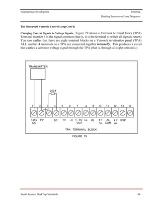
Changing Current Signals to Voltage Signals (Cont'd). Return connections from control
instruments to the signal common at terminal 4 are NOT shown on ILDs.
Note the following from Figure 79: Current flows:
° from terminal 1 to the transmitter
° from the transmitter to terminal 2
° from terminal 2 across the jumper lead to terminal 3
° through the 250 ohm resistor to terminal 4, the signal common.
Remember that Vutronik transmitters operate with 4 - 20mA. If a 4-mA current signal is
received from the transmitter, then Ohm's Law says that the voltage drop across the 250-ohm
resistor is 1 volt, since V = IR = 0.004 x 250 = 1 V.
If a 20-mA current signal is received from the transmitter, then from 0.020 x 250, there is a 5-
v drop across the 250-ohm resistor.
4 - 20 mA is the range of current flow through the transmitter. This is proportional to a 1-5 v
signal at the signal common.
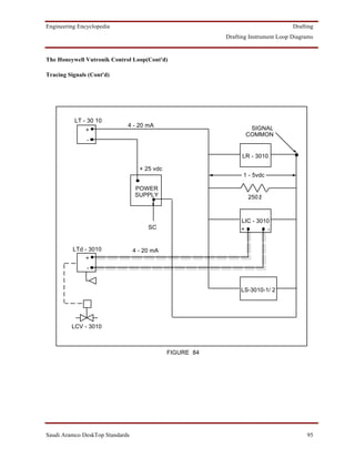
Figure 82 shows a Vutronik system for level control loop 3010. The system is operating a
level recorder, a level indicating controller and an alarm.
Note the symbol [-||-] that is used to denote a switch card.
As an example, we will trace the signal that operates the level recorder, LR - 3010.
A 25 - vdc power supply producing 4 - 20 mA is connected to terminal 1 on TPAI-2. This
supply is not shown on the ILDs. (Remember that other connections, such as the internal
connections between all terminal 4 and the return connections from instruments to terminals 4
are also not shown on ILDs.)
A wire connects terminal 1 on TPAI-2 to the positive side of the transmitter, LT-3010. The
connection is made through CA-41 and FA-1 on the BACK AUXILIARY RACK, RK-D28-
3001-1. From FA-1 the wire goes to TB-E-3007 in the junction box, terminal 1. The wire is
shielded and is earthed at terminal 3.
Saudi Aramco DeskTop Standards 91](https://image.slidesharecdn.com/ild-120401080742-phpapp02/85/ARMACO-STANDARD-93-320.jpg)