Downloaded 1,240 times


![21
Components
of
Control Loops
Transducers
Device that translates a mechanical signal into an electrical signal.
Converters
Device that converts one type of signal into another type of signal.
Transmitters
device that converts a reading from a sensor or transducer into a standard signal
and transmits that signal to a monitor or controller.
Transmitter types include:
-Pressure transmitters -Flow transmitters
-Temperature transmitters -Level transmitters
-Analytic (O2 [oxygen], CO [carbon monoxide], and pH) transmitters](https://image.slidesharecdn.com/inst-160601221226/75/Instrumentation-and-process-control-fundamentals-21-2048.jpg)


The document covers the fundamentals of instrumentation and process control, including definitions, terminology, and the components of control loops. It emphasizes the importance of maintaining controlled conditions in various processes by using sensors, controllers, and corrective actions. The document also highlights key concepts such as set points, process variables, and the role of various instruments in managing and controlling processes.
An introduction slide presenting the topic of instrumentation and process control fundamentals.
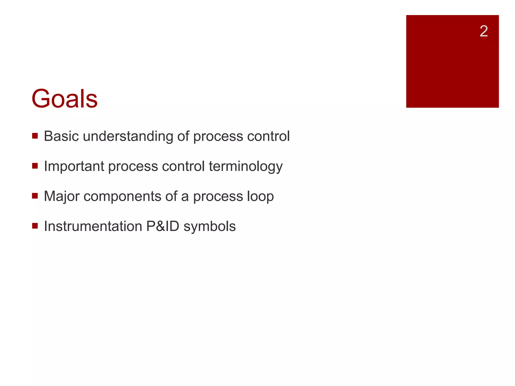
Goals include understanding process control, key terminology, components of a process loop, and P&ID symbols.
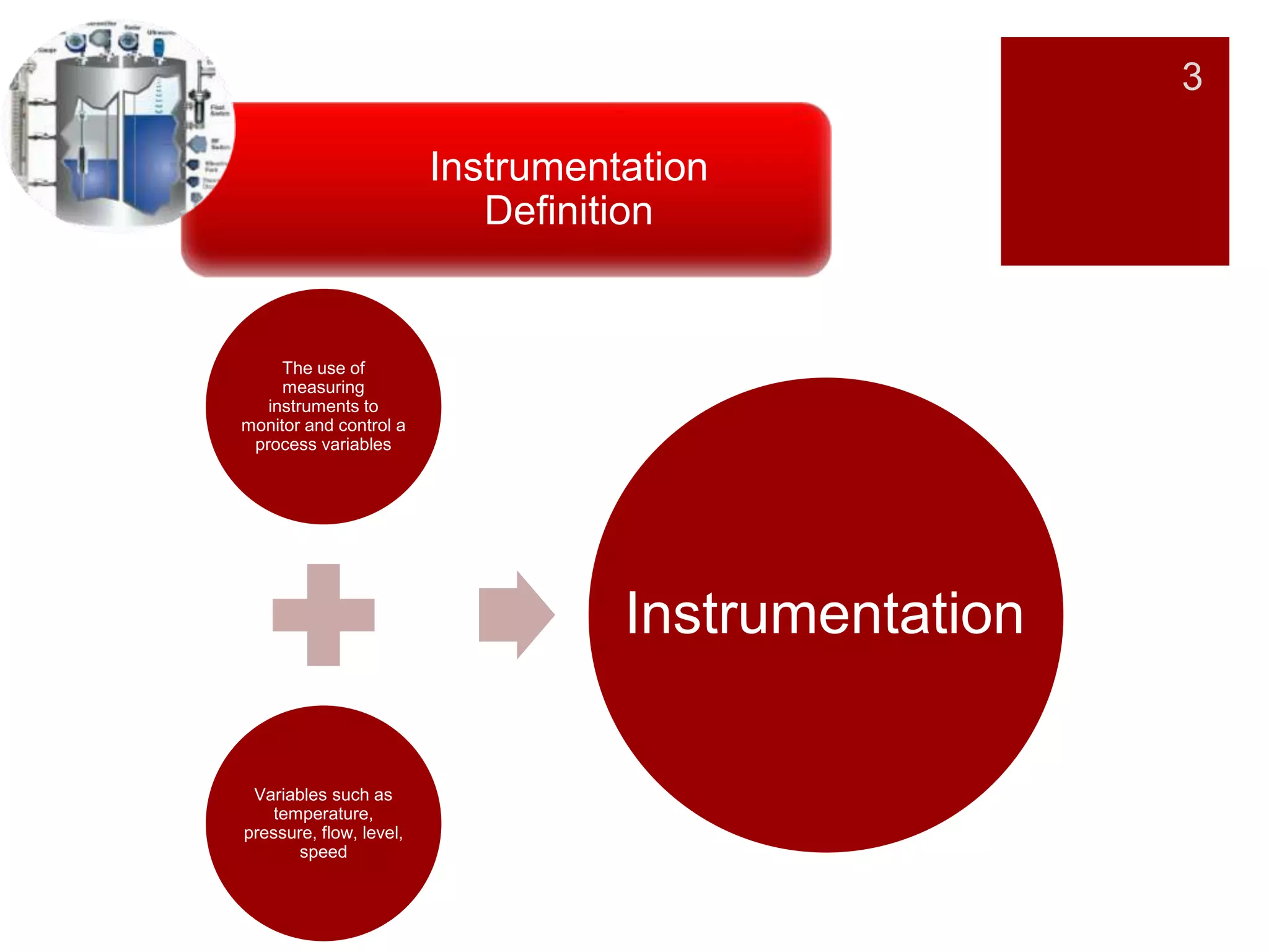
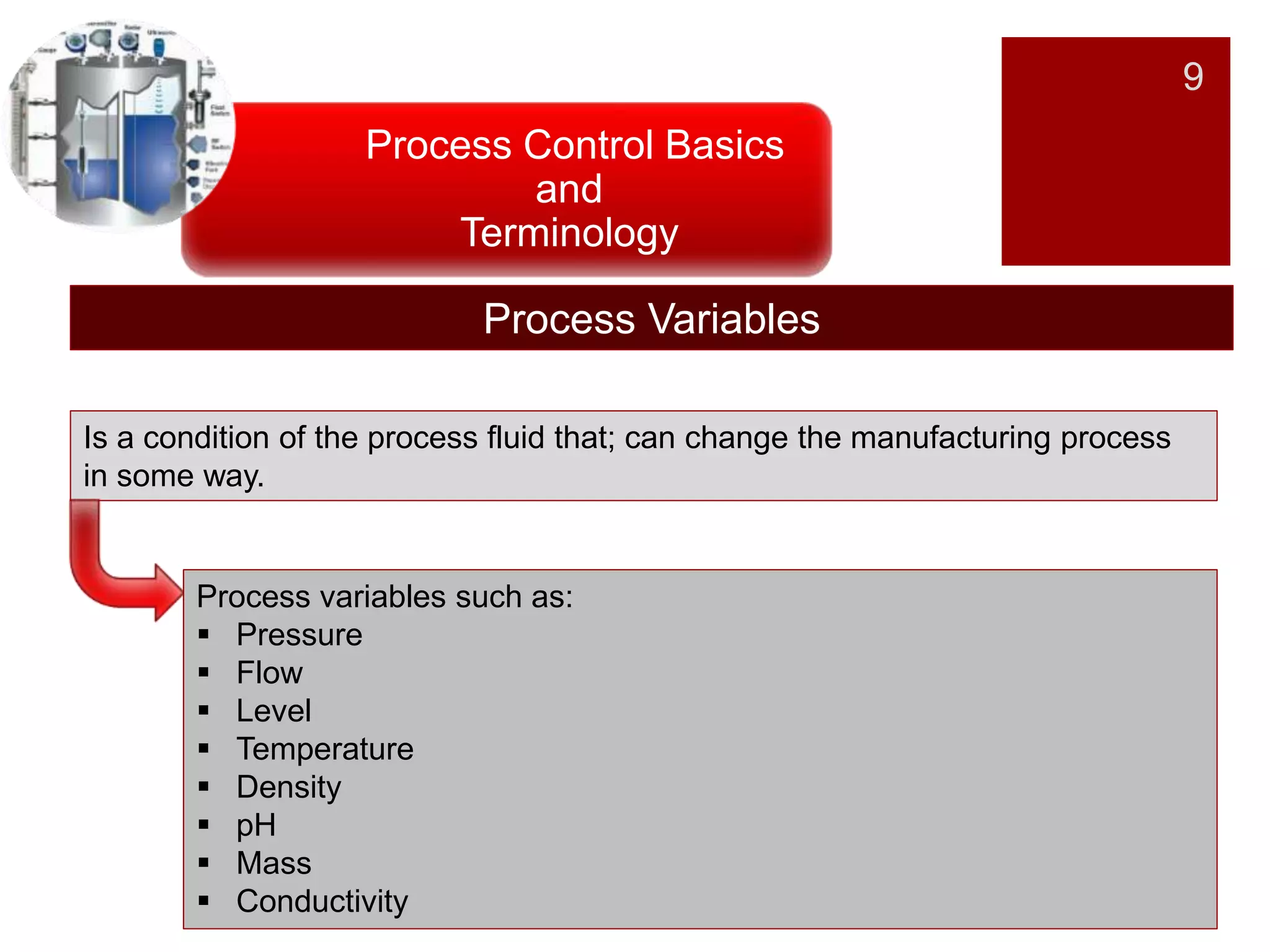
Definitions of instrumentation and process control, focusing on variables like temperature and pressure.
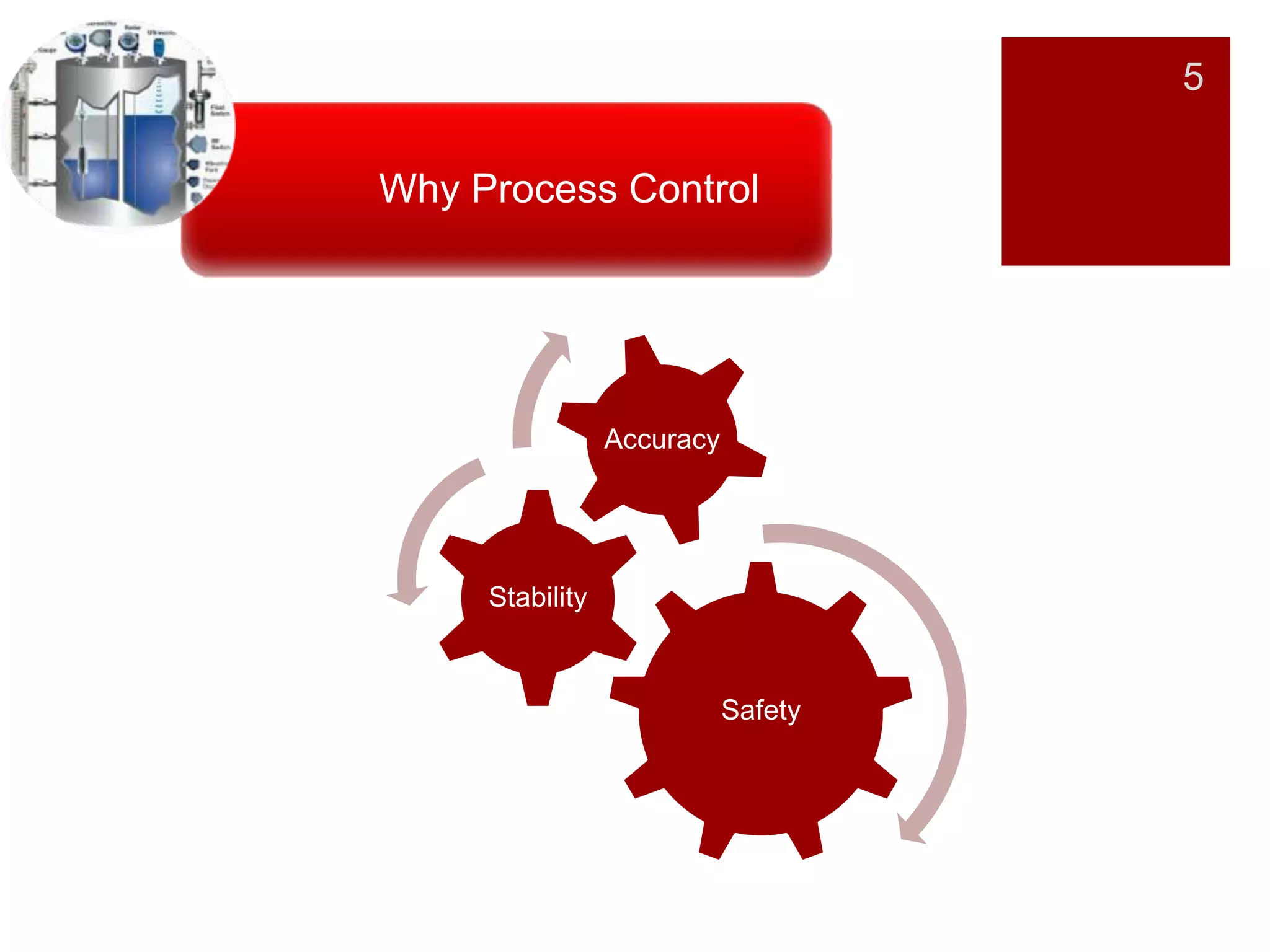
Key reasons for process control: safety, stability, and accuracy in industrial systems.
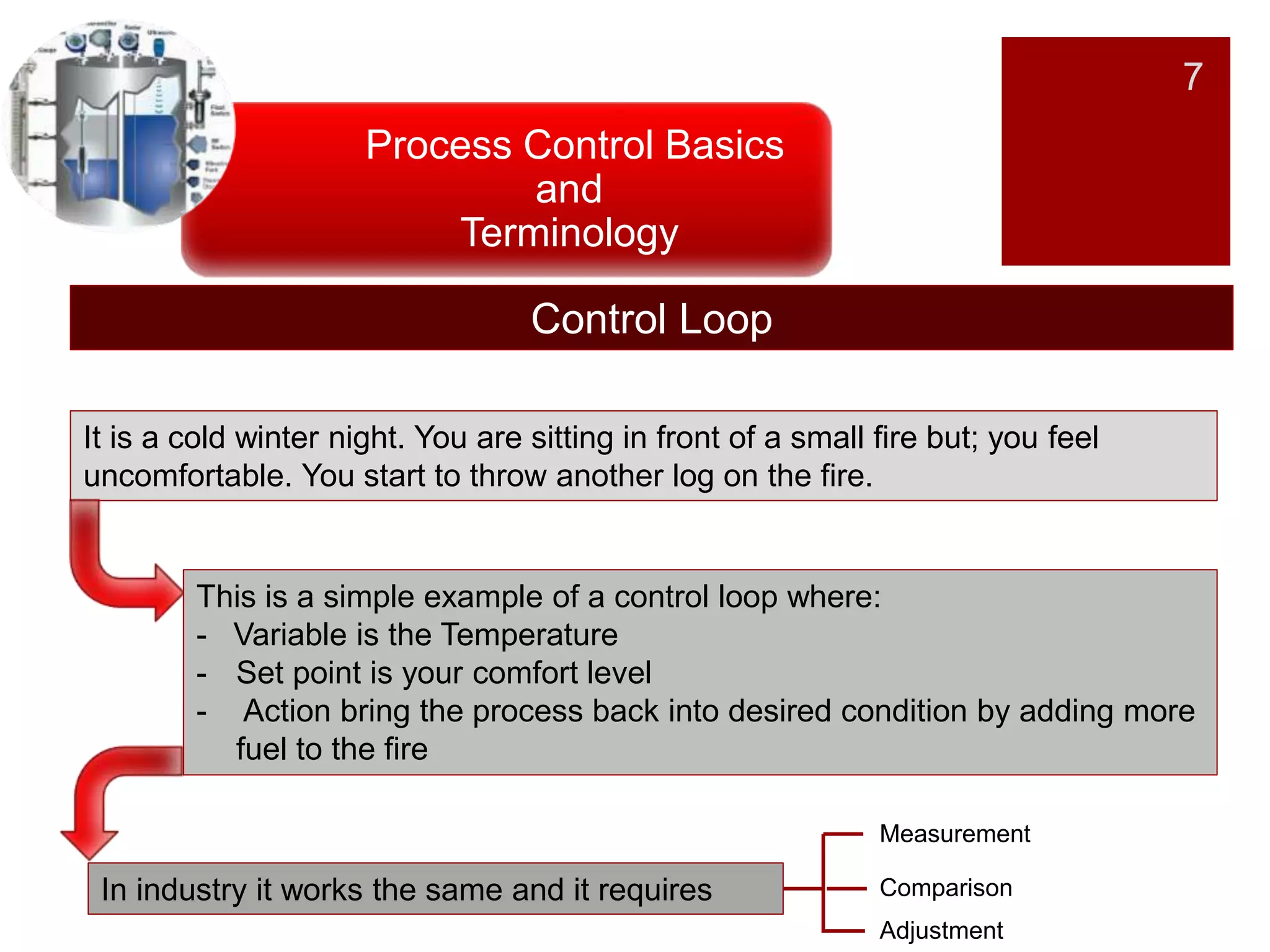
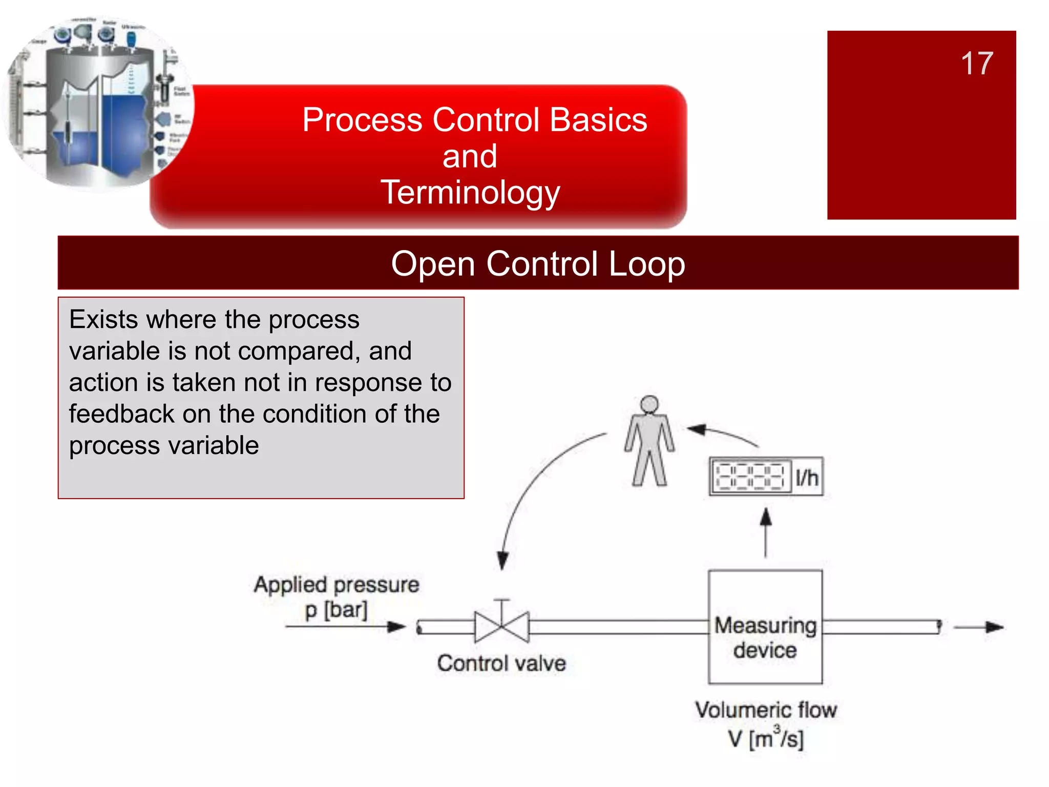
An introduction to basic terminology and concepts, illustrated by examples of control loops.
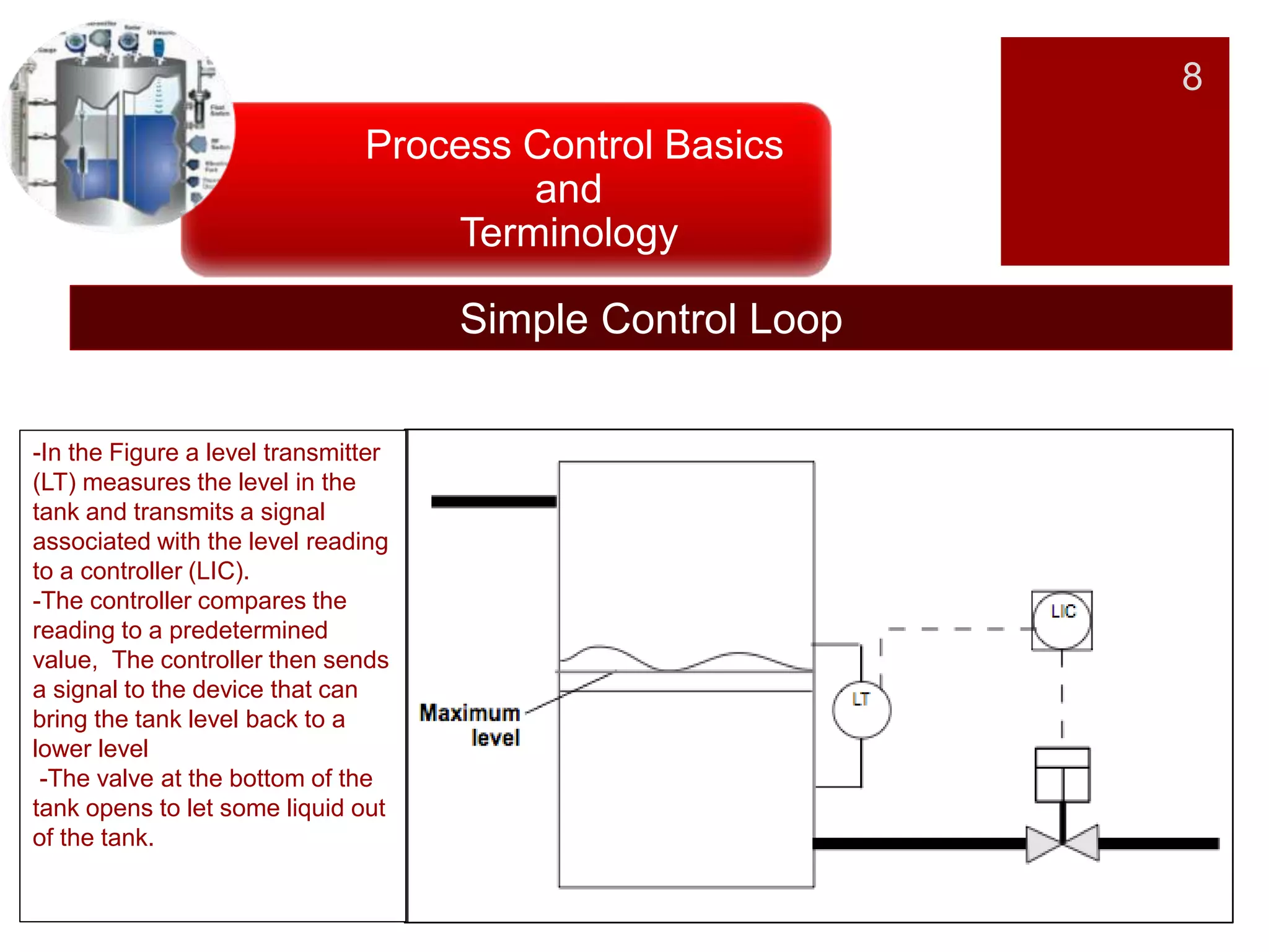
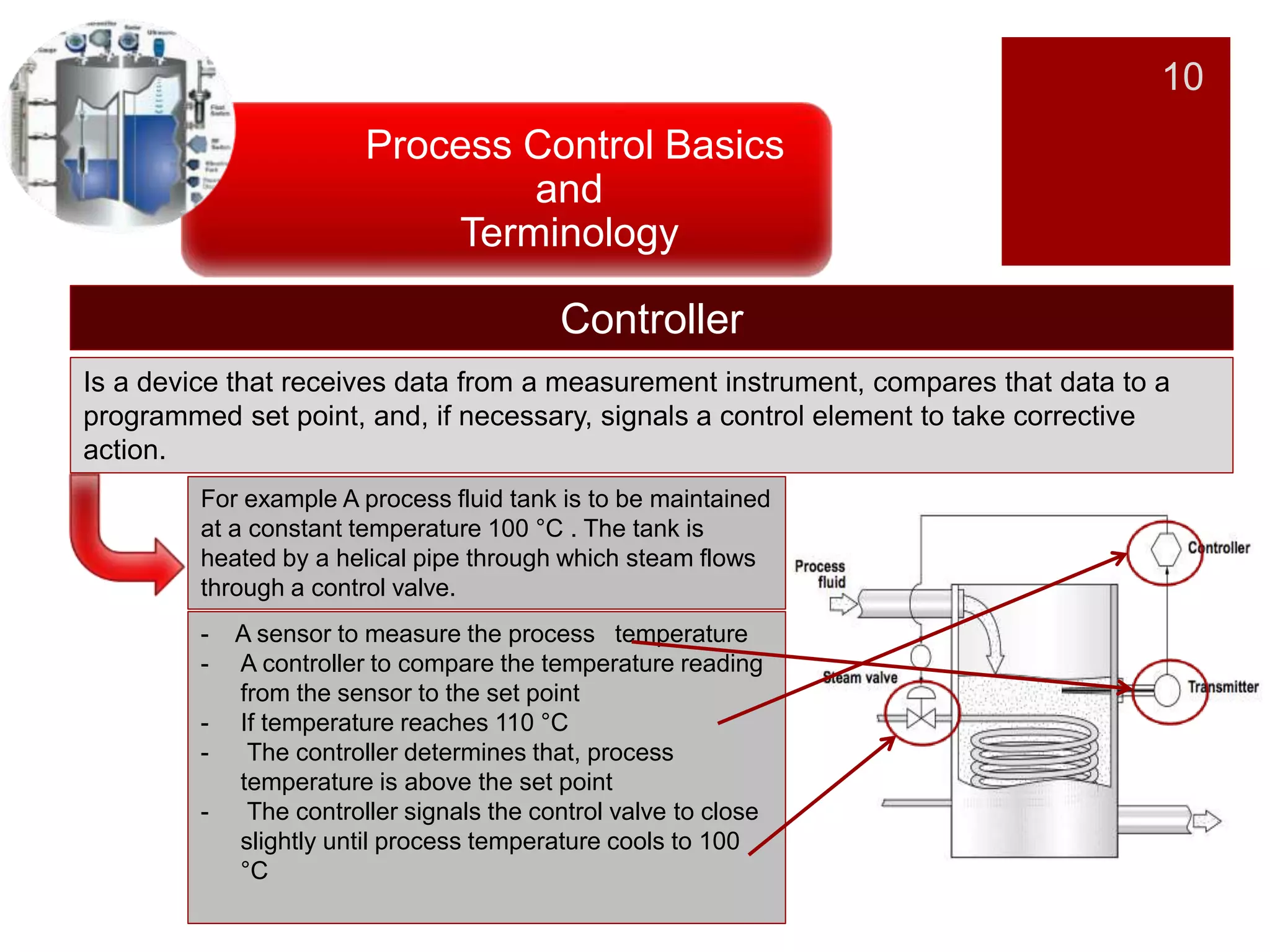
Details on control loops, including measurement devices, set points, controllers, and maintenance actions.
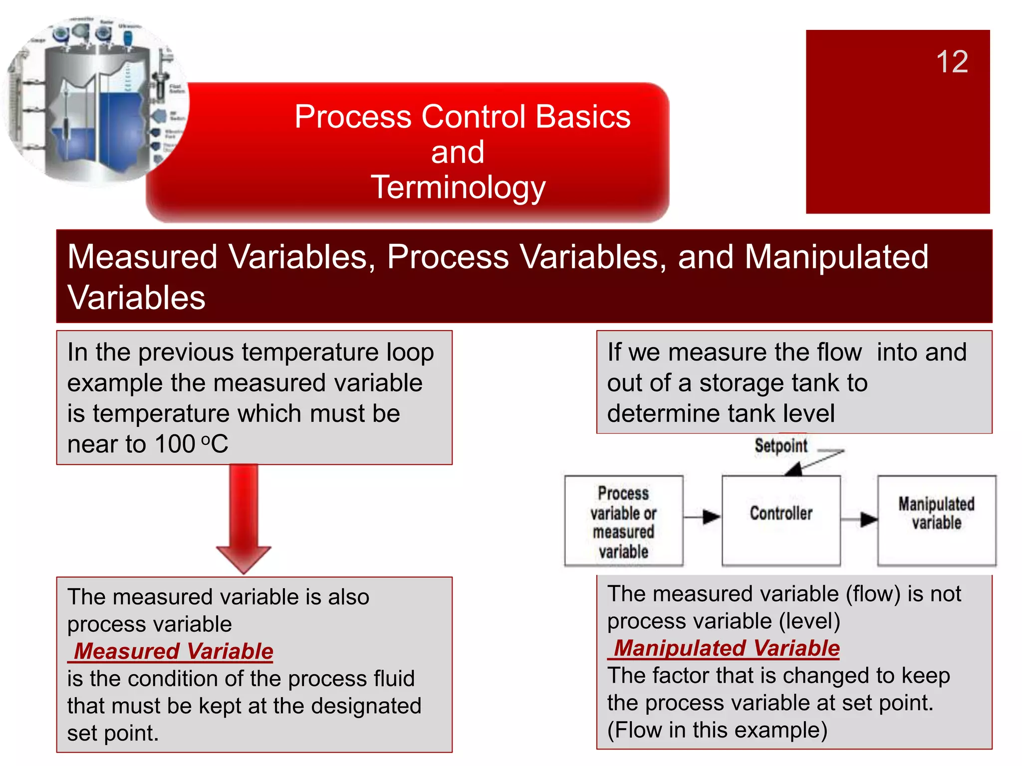
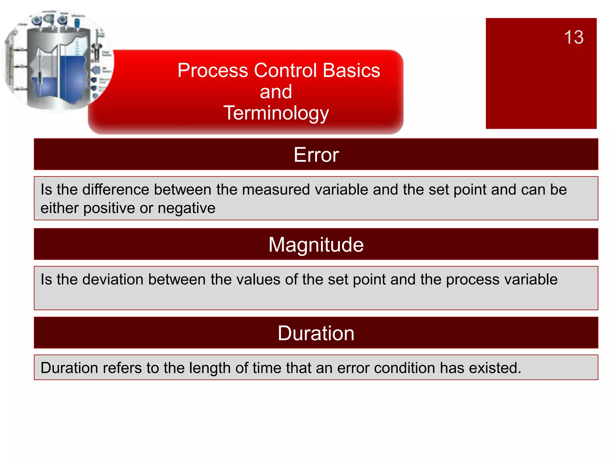
Different terms including set points, measured variables, manipulated variables, and error definitions.
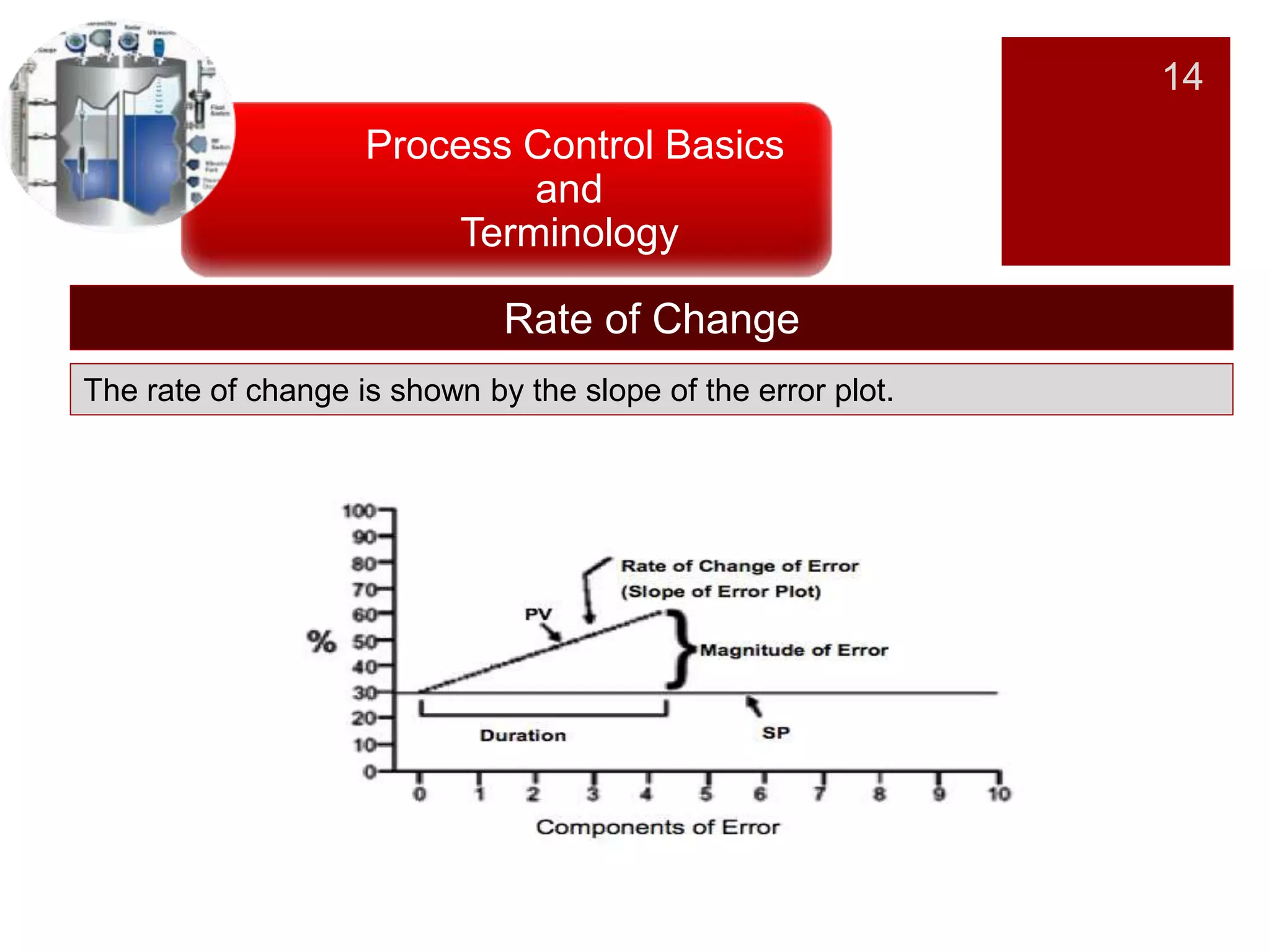
Explains concepts like the rate of change, offset, load disturbance, and their implications in control systems.
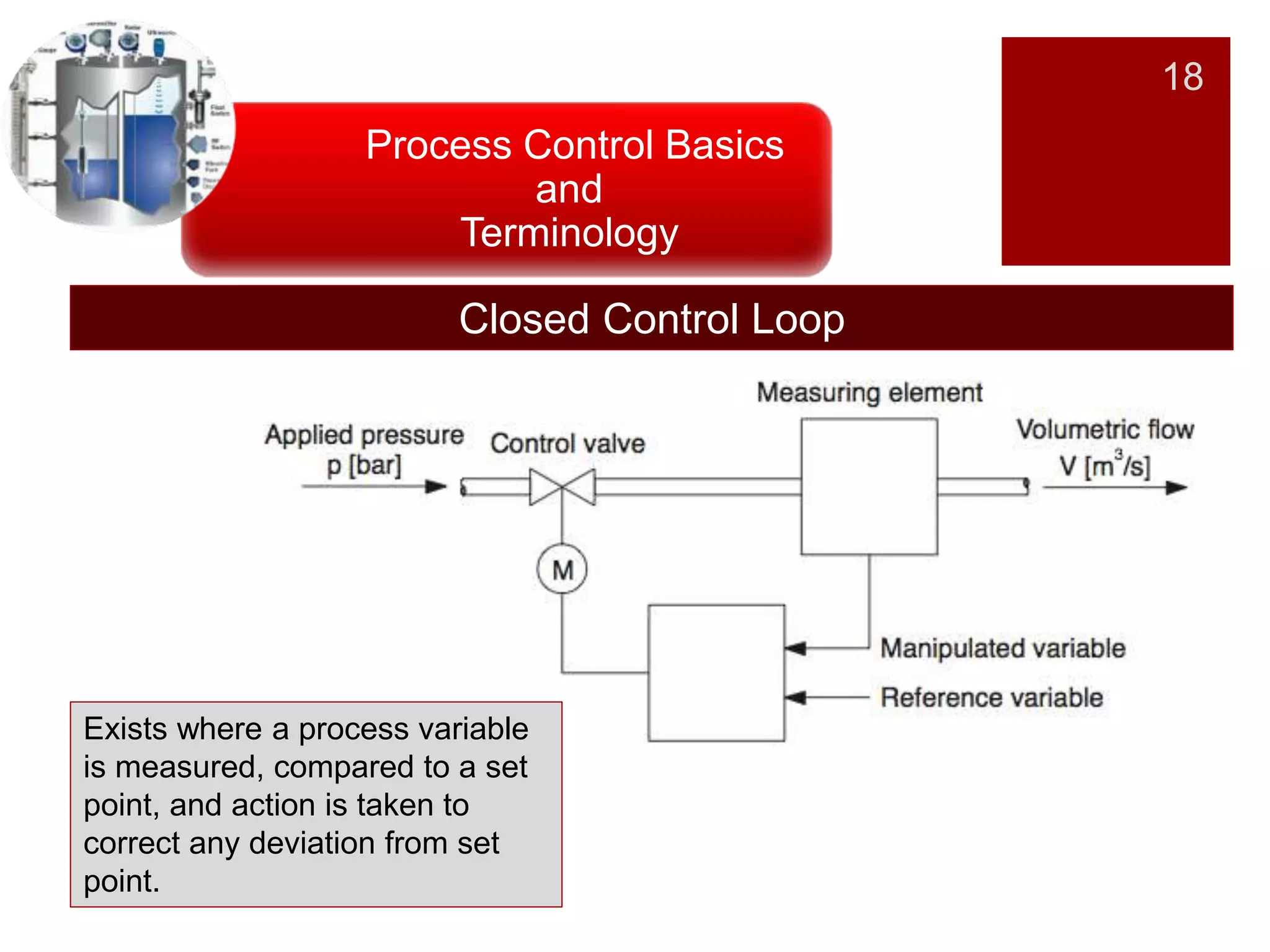
Distinguishes between open and closed control loops, focusing on feedback mechanisms.
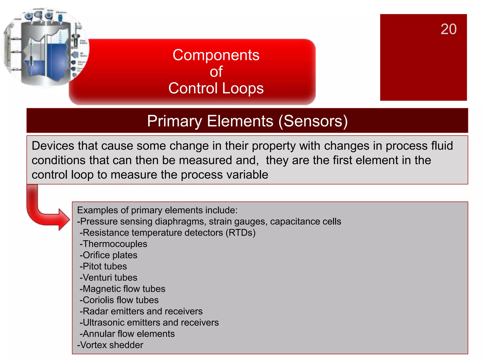
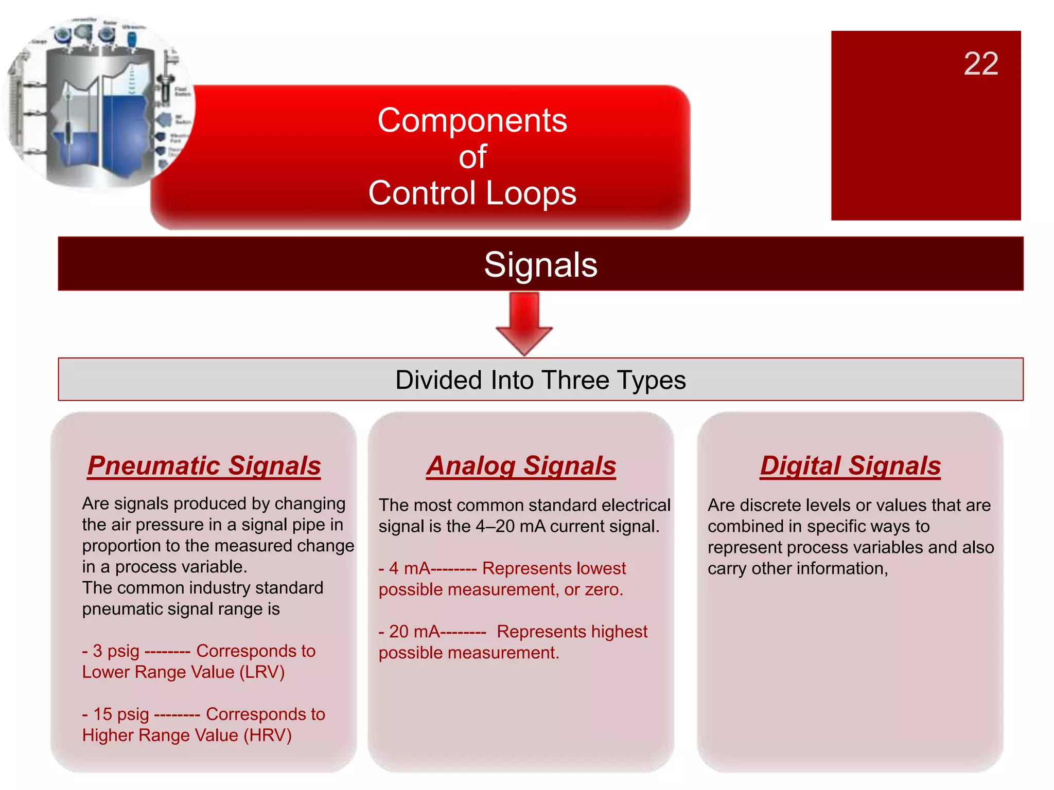
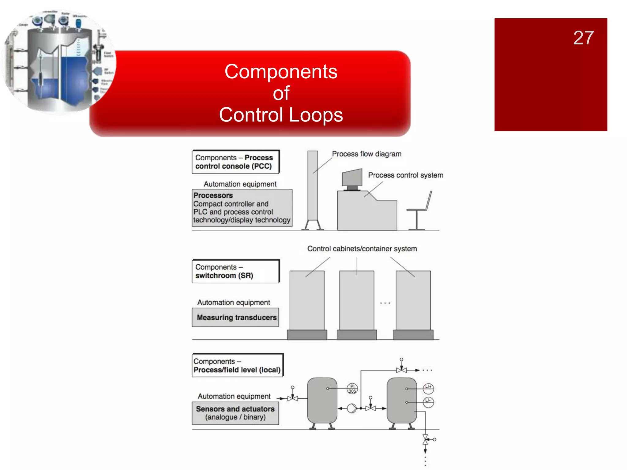
Introduction to components of control loops essential for process control.
Discusses primary elements like sensors and their role in measuring process variables.
Describes devices that transform signals for monitoring and controlling processes.
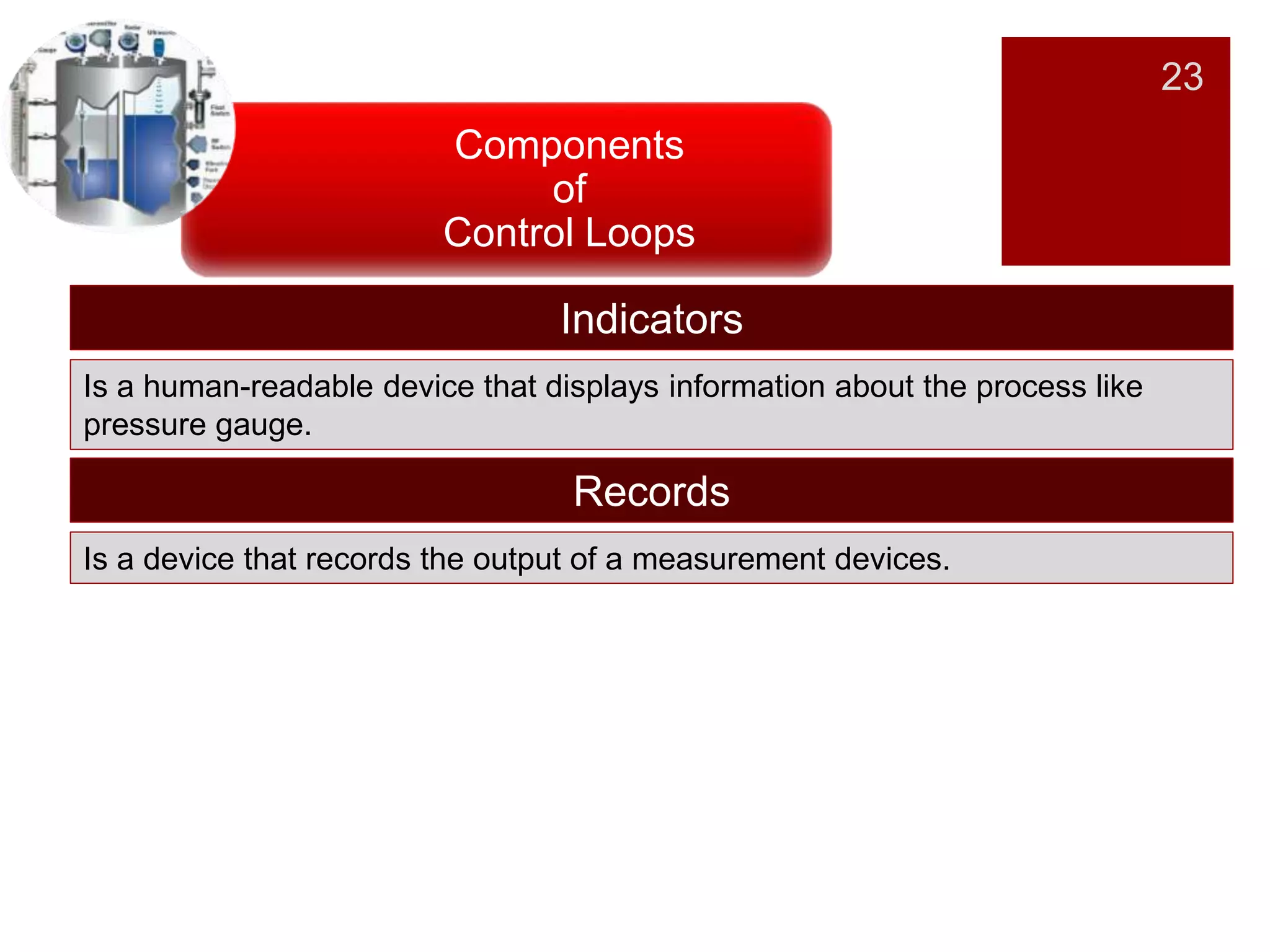
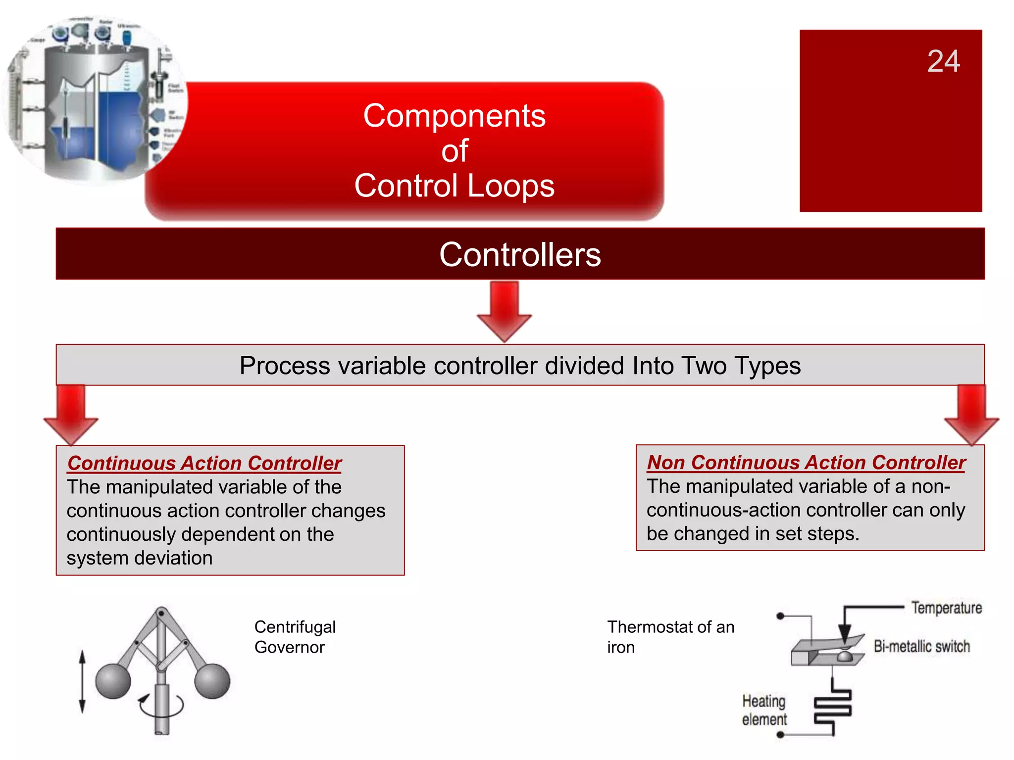
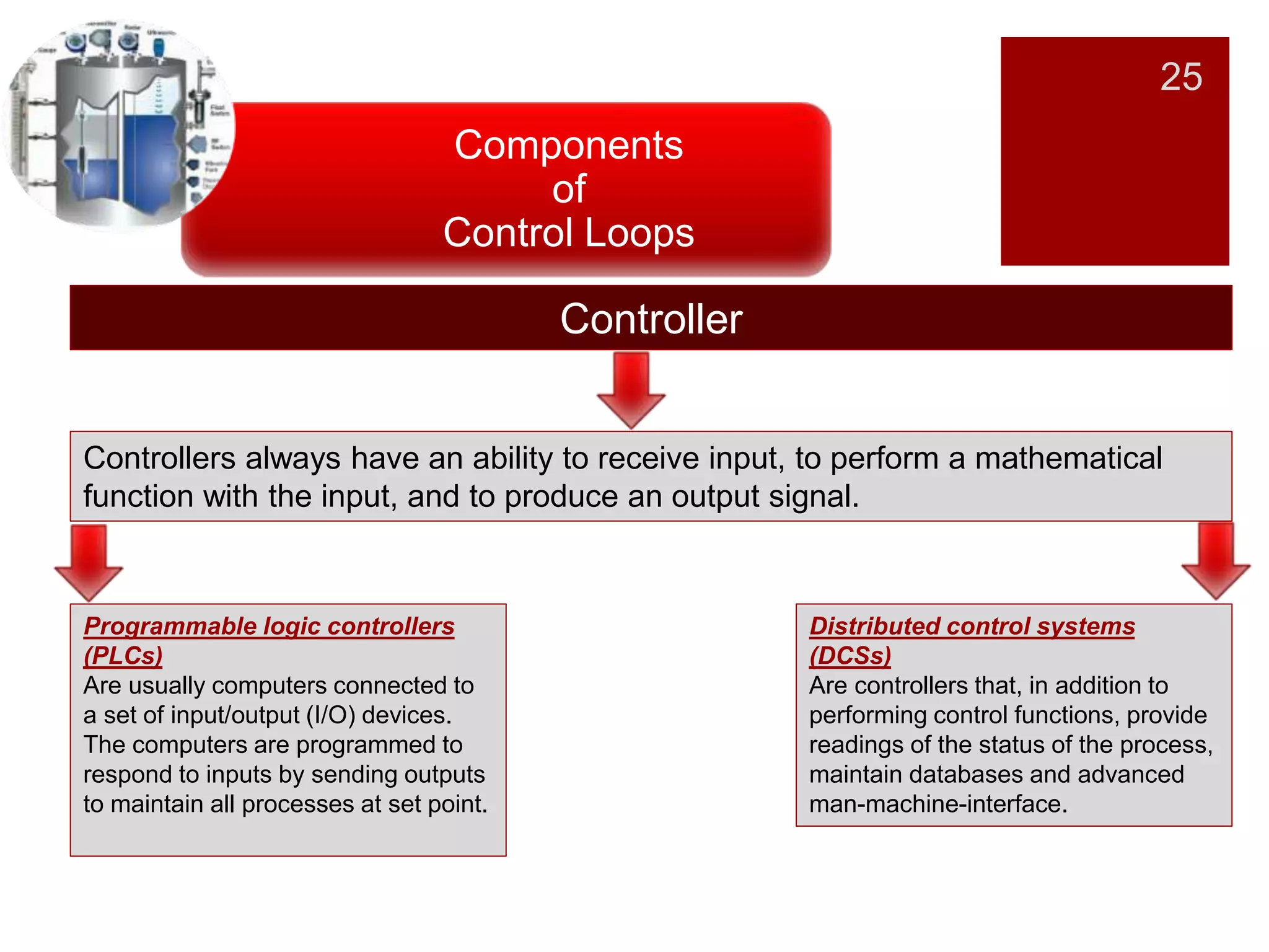
Overview of indicators, recording devices, and types of controllers used in control loops.
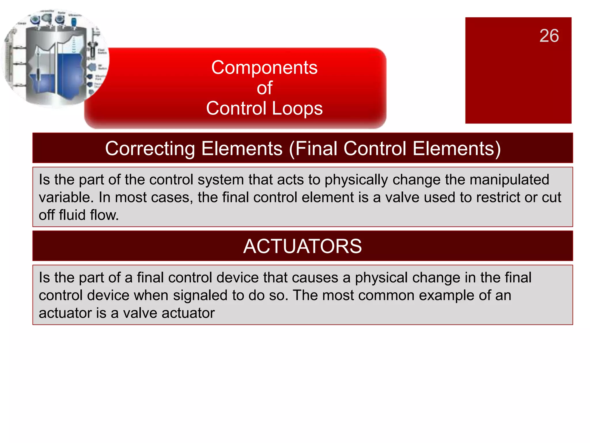
Details on final control elements that physically adjust manipulated variables.
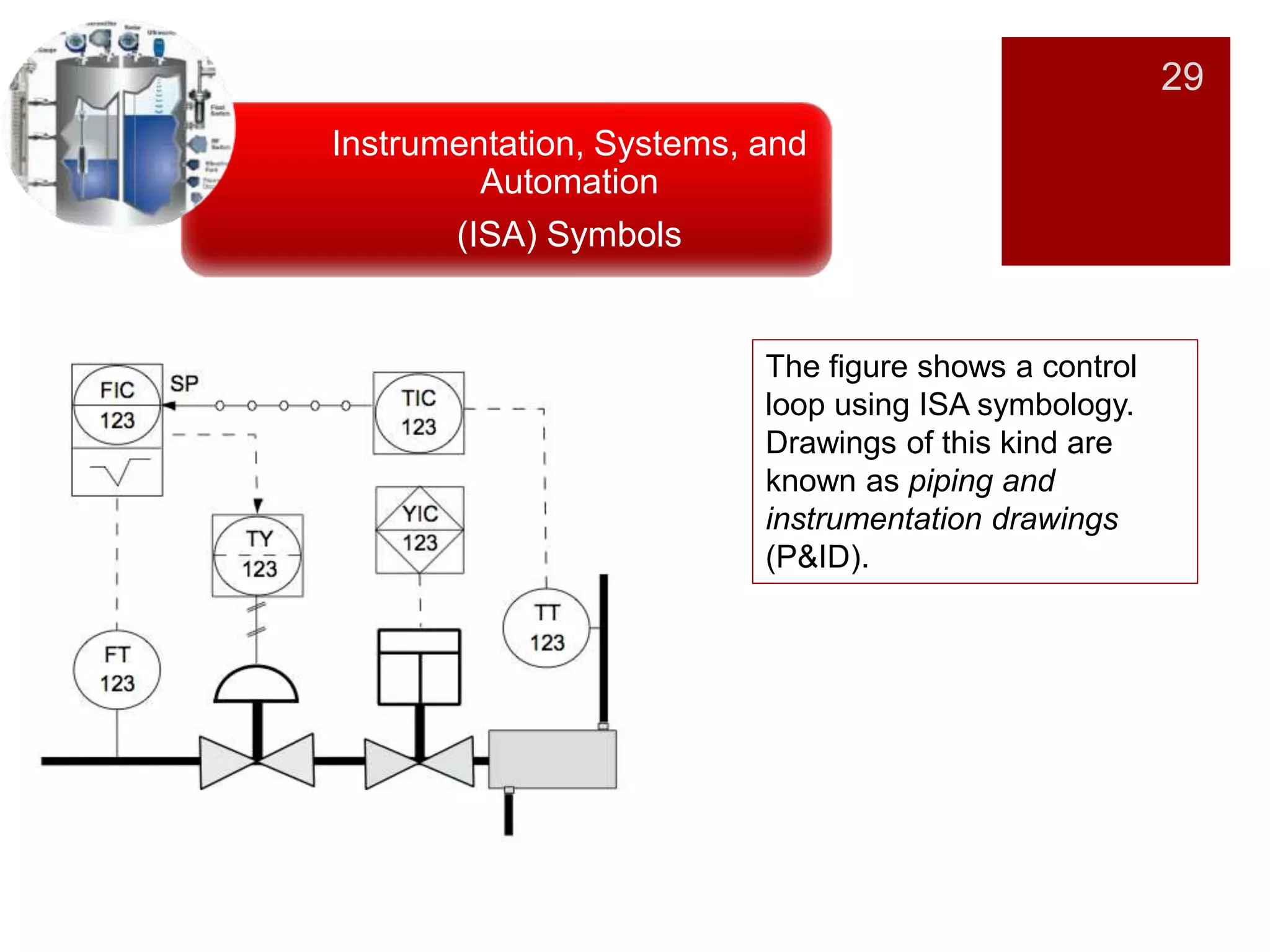
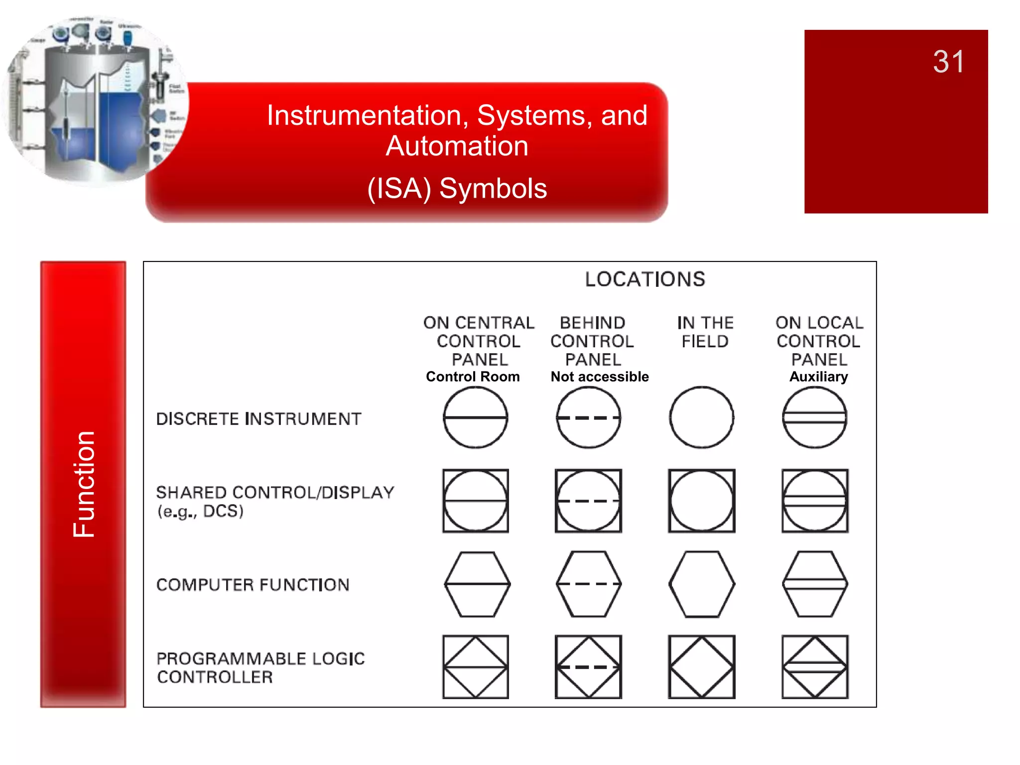
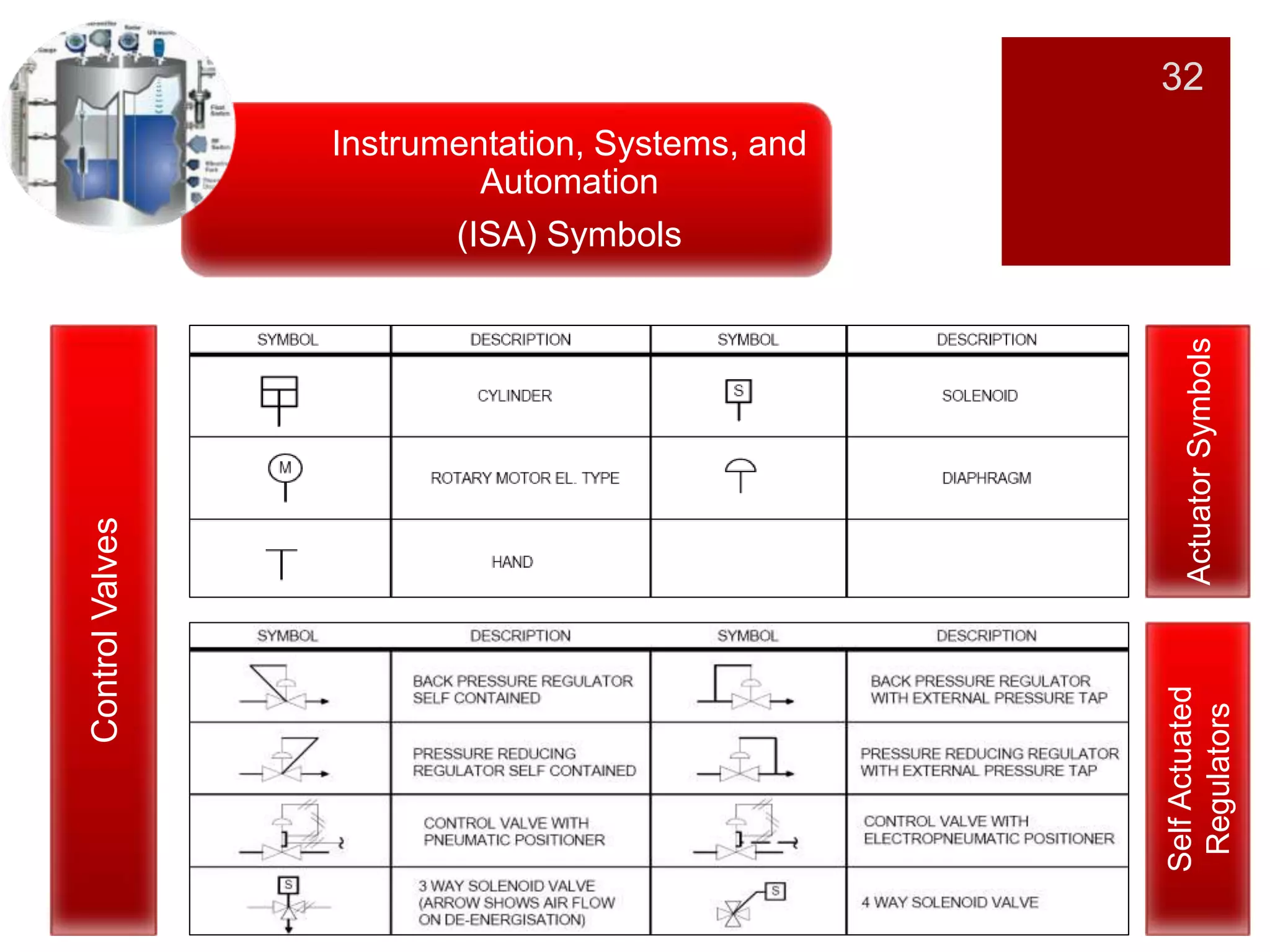
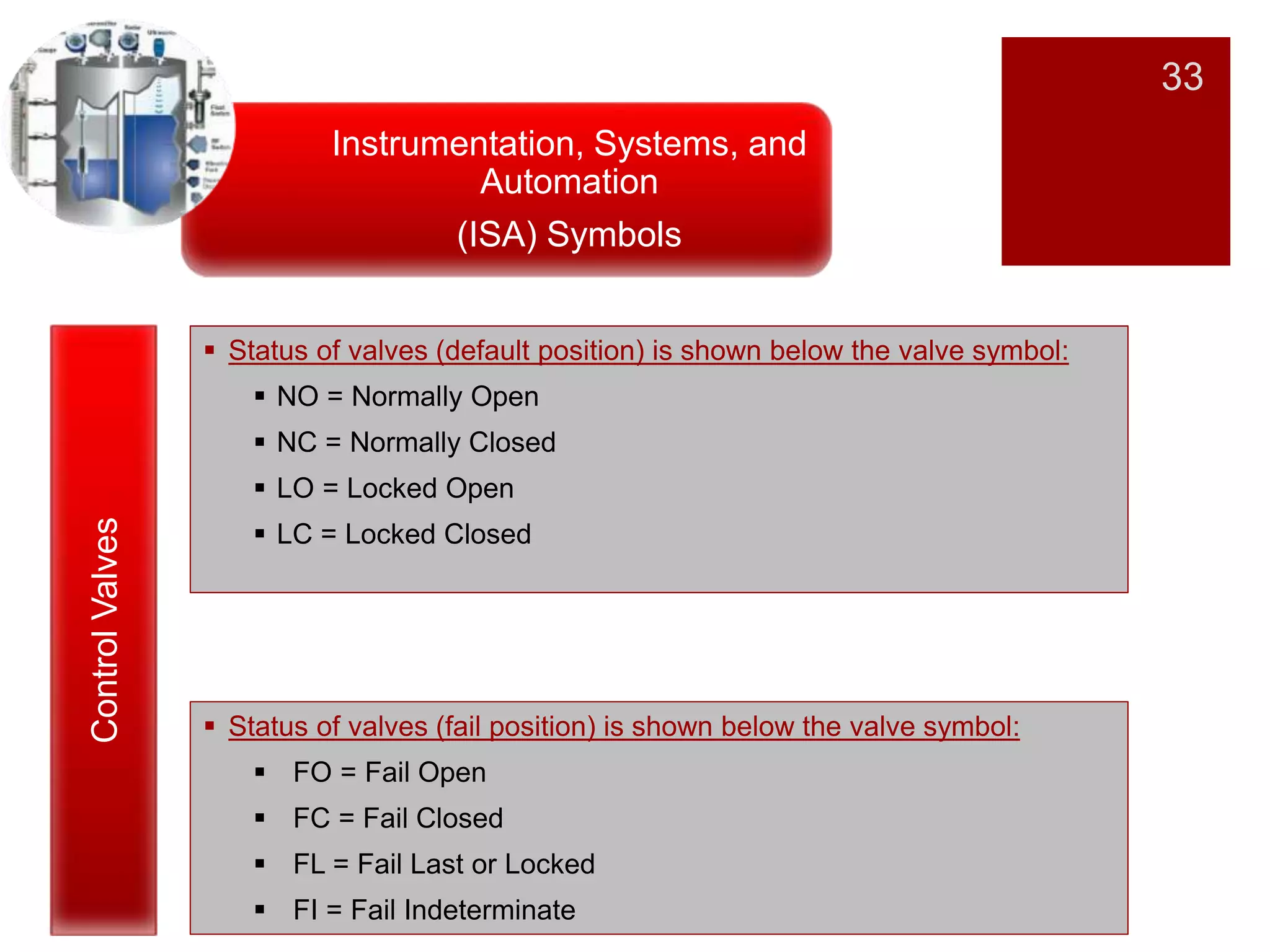
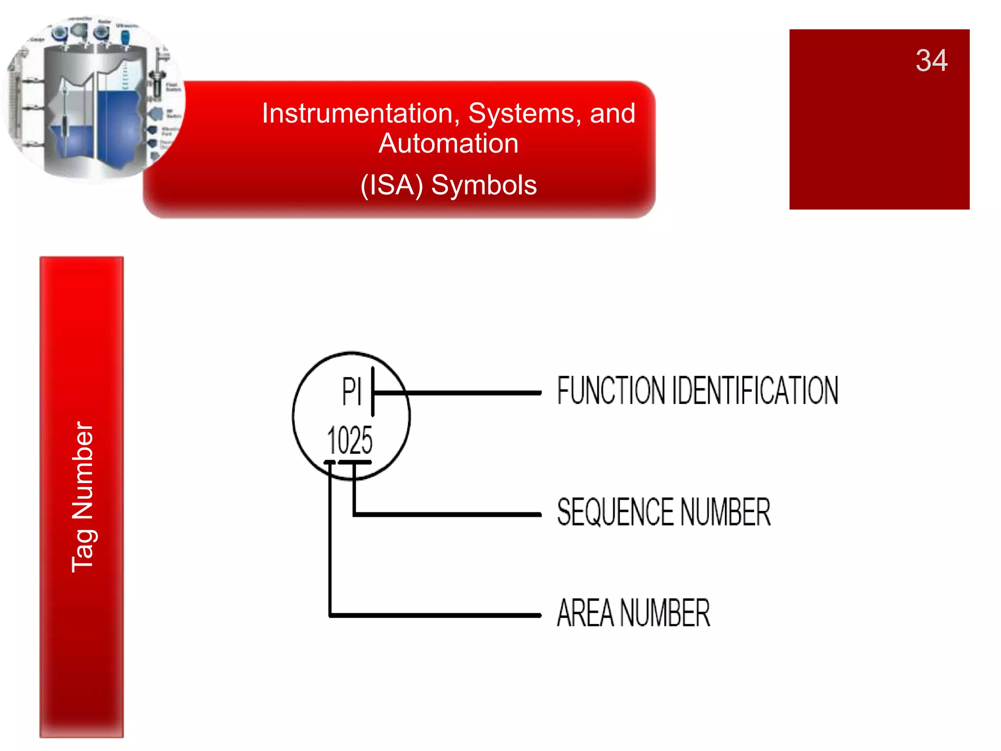
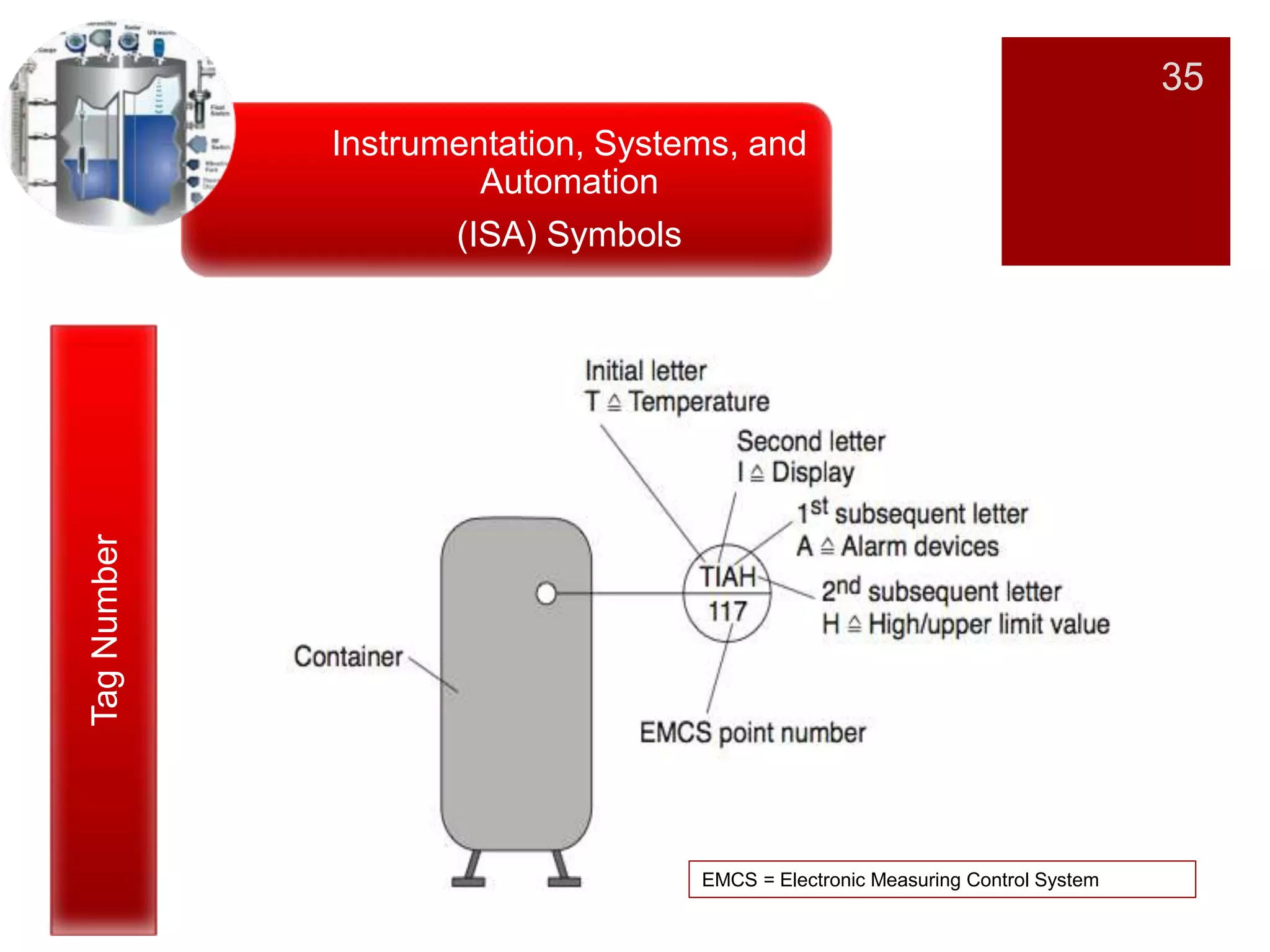
Introduction to ISA symbols, their significance in representing control components in diagrams.
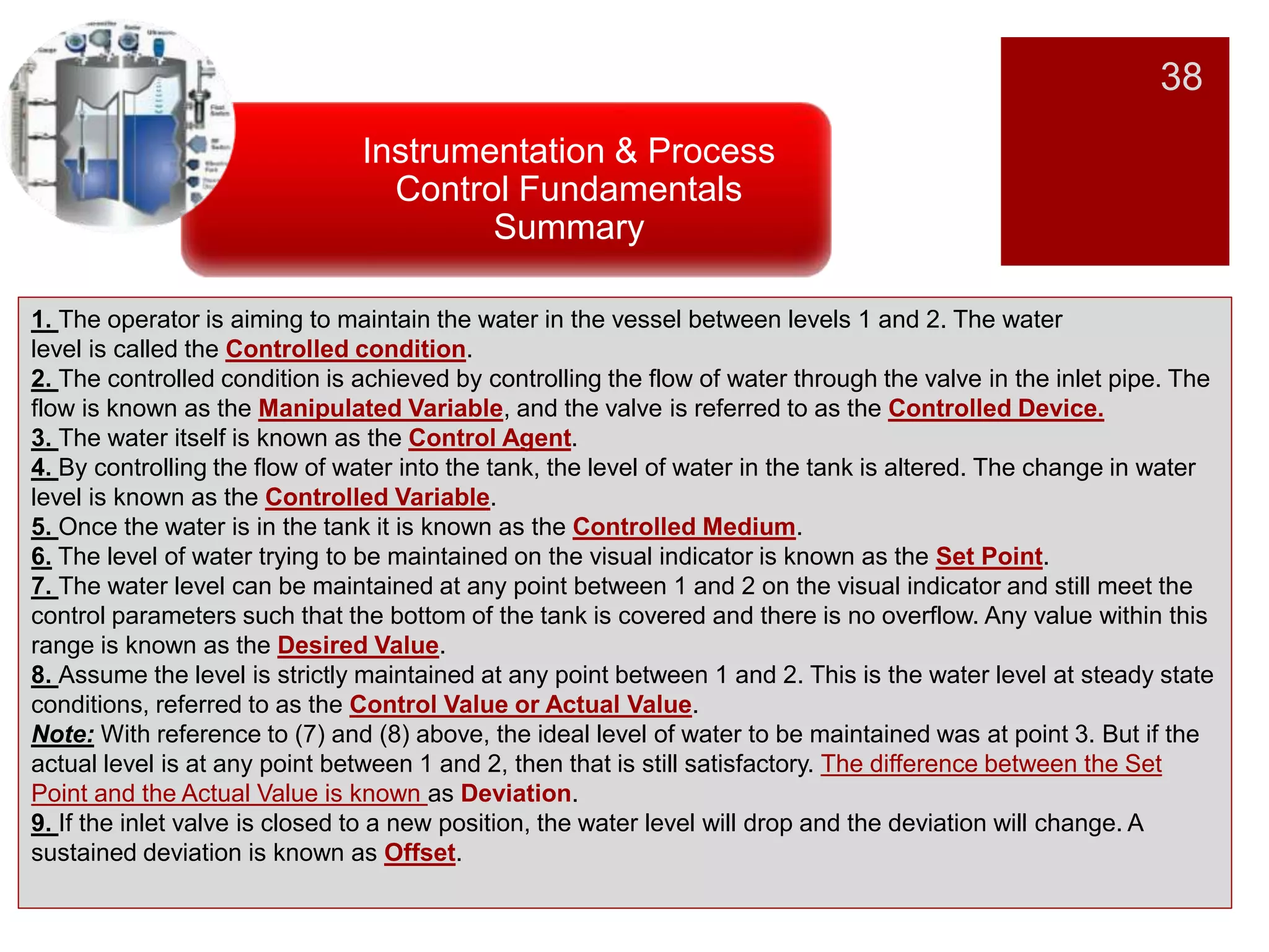
Summarizes the key concepts of maintaining water levels in a control system as an illustrative example.
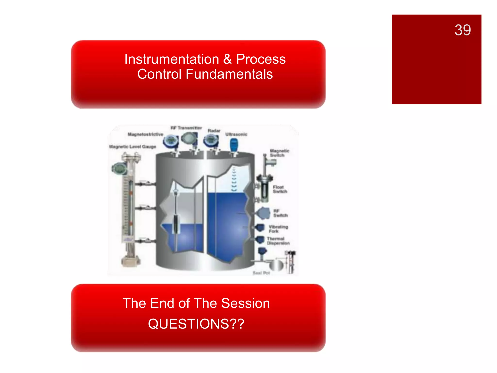
Final slide inviting questions, concluding the presentation on instrumentation and process control fundamentals.