This document is the American National Standard ANSI/ISA-5.1-2009 which provides standardized instrumentation symbols and identification. It defines mandatory identification letters, graphic symbols, and their dimensions to facilitate communication about measurement and control systems. The standard aims to strengthen its role as a communication tool across industries involving measurement and control. Key elements include standardized identification letters, graphic symbol tables, dimensional requirements, and guidelines for application.


![- 19 - ANSI/ISA-5.1-2009
3.1.16 computing relay:
an alternate term for a device that performs one or more calculations or logic operations, or both, and
transmits one or more resultant output signals; see also computing device.
3.1.17 computing function:
a hardware or software function that performs one or more calculations or logic operations, or both, and
transmits one or more resultant output signals.
3.1.18 configurable:
a term for devices or systems whose functional and/or communication characteristics can be selected or
rearranged through setting of program switches, application software, fill-in-the-blank forms, pull-down
menus, entered values or text, and/or other methods, other than rewiring as a means of altering the
configuration.
3.1.19 controller:
a device having an output that varies to regulate a controlled variable in a specified manner that may be a
self-contained analog or digital instrument, or may be the equivalent of such an instrument in a shared-
control system.
a) an automatic controller varies its output automatically in response to a direct or indirect input of a
measured process variable.
b) a manual controller, or manual loading station, varies its output in response to a manual
adjustment; it is not dependent on a measured process variable.
c) a controller may be an integral element of other functional elements of a control loop.
3.1.20 control station:
a manual loading station that also provides switching between manual and automatic control modes of a
control loop; see also auto-manual station.
a). the operator interface of a distributed control system may be referred to as a control station.
3.1.21 control valve:
a device, other than a common, hand-actuated process block valve or self-actuated check valve, that
directly manipulates the flow of one or more fluid process streams.
a) the designation "hand control valve" shall be limited to hand-actuated valves that when used for
process throttling require identification as an instrument or control device.
3.1.22 converter:
a device that receives information as one form of an instrument signal and transmits an output signal as
another form, such as a current-to-pneumatic signal converter.
a). an instrument that changes a sensor’s output to a standard signal, is properly designated as a
transmitter, not a converter; typically, a temperature element [TE] connects to a transmitter [TT], not to a
converter [TY].
Copyright International Society of Automation
Provided by IHS under license with ISA
Not for ResaleNo reproduction or networking permitted without license from IHS
--`,,```,,,,````-`-`,,`,,`,`,,`---
//^:^^#^~^^"#@::"~^$:~@""#:$@^"*^~@~$"~~""^^:@^^:#^~~](https://image.slidesharecdn.com/instrumentationsymbolsandidentification-200628175106/75/Instrumentation-symbols-and_identification-19-2048.jpg)
![- 25 - ANSI/ISA-5.1-2009
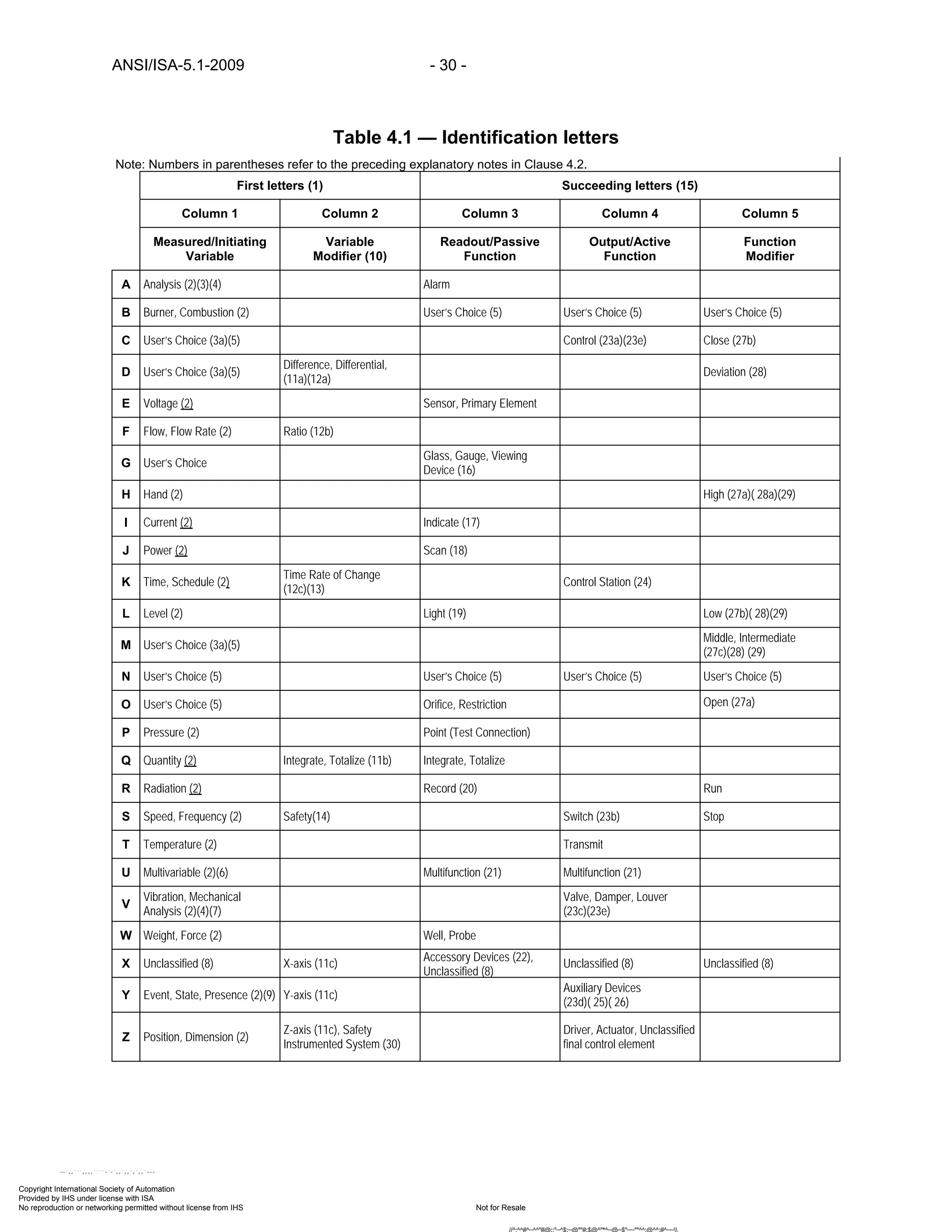
4 Identification letters table
4.1 Identification letters table
4.1.1 This clause provides in tabular form the alphabetic building blocks of the Instrument and Function
Identification System in a concise, easily referenced manner.
4.1.2 Table 4.1, together with Clause 4.2, defines and explains the meanings of the individual letters
when used to identify loop and device functions.
4.1.3 The letters in Table 4.1 shall have the mandatory meanings assigned except the user shall
assign:
a) Variables to the User’s Choice letters in column 1 and functions to the User’s Choice
letters in columns 3, 4 and 5 when such letters are used.
b) Meanings to the blanks in columns 2, 3, 4, and 5 when additional functions or modifiers
are assigned.
c) When such assignments are made they shall be documented in the User’s engineering
and design standards or guidelines and on drawing legend sheets.
4.2 Table 4.1 — Identification letters explanatory notes
The following notes, indicated in Table 4.1 by parentheses, are to be used as an aid in understanding the
meanings of the letters when they are used in certain positions in Loop Identification Letter(s) or
Functional Identifications.
(1) First Letters are a Measured/Initiating Variable and, if required, a combination of a
Measured/Initiating Variable and a Variable Modifier that shall be referred to by the combined meaning.
(2) The specific meanings given for Measured/Initiating Variables [A], [B], [E], [F], [H], [I], [J], [K] [L],
[P], [Q], [R], [S], [T], [U], [V], [W], [Y], and [Z] shall not be modified.
(3) Measured/Initiating Variable analysis [A] shall be used for all types of process stream composition
and physical property analysis. The type of analyzer, and for stream component analyzers the
components of interest, shall be defined outside the tagging bubble.
(a) “User’s Choice” Measured/Initiating Variables [C], [D], and [M] are assigned to identify
conductivity, density, and moisture analysis, respectively, when it is the user’s common practice.
(4) Measured/Initiating Variable analysis [A] shall not be used to identify vibration or other types of
mechanical or machinery analysis, which shall be identified by Measured/Initiating Variable vibration or
mechanical analysis [V].
(5) “User’s Choice” letters [C], [D], [M], [N], and [O] that cover unlisted repetitive meanings that may
have one meaning as a Measured or Initiating Variable and another as a Succeeding-Letter shall be
defined only once. For example, [N] may be defined as “modulus of elasticity” as a Measured/Initiating
Variable and “oscilloscope” as a Readout/Passive Function.
(6) Measured/Initiating Variable multivariable [U] identifies an instrument or loop that requires
multiple points of measurement or other inputs to generate single or multiple outputs, such as a PLC that
uses multiple pressure and temperature measurements to regulate the switching of multiple on-off valves.
Copyright International Society of Automation
Provided by IHS under license with ISA
Not for ResaleNo reproduction or networking permitted without license from IHS
--`,,```,,,,````-`-`,,`,,`,`,,`---
//^:^^#^~^^"#@::"~^$:~@""#:$@^"*^~@~$"~~""^^:@^^:#^~~](https://image.slidesharecdn.com/instrumentationsymbolsandidentification-200628175106/75/Instrumentation-symbols-and_identification-25-2048.jpg)
![ANSI/ISA-5.1-2009 - 26 -
(7) Measured/Initiating Variable vibration or mechanical analysis [V] is intended to perform the
function in machinery monitoring that Measured/Initiating Variable analysis [A] performs in process
monitoring and except for vibration, it is expected that the variable of interest will be defined outside the
tagging bubble.
(8) First-Letter or Succeeding-Letter for unclassified devices or functions [X] for non-repetitive
meanings that are used only once or to a limited extent may have any number of meanings that shall be
defined outside the tagging bubble or by a note in the document. For example, [XR-2] may be a stress
recorder and [XX-4] may be a stress oscilloscope.
(9) Measured/Initiating Variable event, state, or presence [Y] is intended for use when control or
monitoring responses are not driven by time or time schedule--but driven by events, presence, or state.
(10) Measured/Initiating Variable and Variable Modifier combinations shall be selected according to
how the property being measured is modified or changed.
(11) Direct measured variables that shall be considered as Measured/Initiating Variables for Loop
Numbering shall include but are not limited to:
(a) Differential [D] — pressure [PD] or temperature [TD].
(b) Total [Q] — flow totalizer [FQ], when directly measured, such as by a positive
displacement flowmeter.
(c) X-axis, y-axis, or z-axis [X], [Y], or [Z] — vibration [VX], [VY], and [VZ], force [WX], [WY],
or [WZ] or position [ZX], [ZY], or [ZZ].
(12) Derived or calculated from other direct measured variables that should not be considered as
Measured/Initiating Variables for Loop Numbering shall include but are not limited to:
(a) Difference [D] — temperature [TD] or weight [WD].
(b) Ratio [F] — Flow [FF], pressure [PF], or temperature [TF].
(c) Time rate of change [K] — pressure [PK], temperature [TK], or weight [WK].
(13) Variable Modifier time or time schedule [K] in combination with a Measured/Initiating Variable
signifies a time rate of change of the measured or initiating variable; [WK], represents a rate-of-weight-
loss loop.
(14) Variable Modifier safety [S] is technically not a direct-measured variable but is used to identify
self-actuated emergency protective primary and final control elements only when used in conjunction with
Measured/Initiating Variables flow [F], pressure [P] or temperature [T]. And because of the critical nature
of such devices, [FS, PS, and TS] shall be considered as Measured/ Initiating Variables in all Loop
Identification Number construction schemes:
(a) Flow safety valve [FSV] applies to valves intended to protect against an emergency
excess flow or loss of flow condition. Pressure safety valve [PSV] and temperature safety valve
[TSV] apply to valves intended to protect against emergency pressure and temperature
conditions. This applies regardless of whether the valve construction or mode of operation places
it in the category of safety valve, relief valve, or safety relief valve.
(b) A self-actuated pressure valve that prevents operation of a fluid system at a higher-than-
desired pressure by bleeding fluid from the system is a backpressure control valve [PCV], even if
the valve is not intended to be used normally. However, this valve is designated a pressure
Copyright International Society of Automation
Provided by IHS under license with ISA
Not for ResaleNo reproduction or networking permitted without license from IHS
--`,,```,,,,````-`-`,,`,,`,`,,`---
//^:^^#^~^^"#@::"~^$:~@""#:$@^"*^~@~$"~~""^^:@^^:#^~~](https://image.slidesharecdn.com/instrumentationsymbolsandidentification-200628175106/75/Instrumentation-symbols-and_identification-26-2048.jpg)
![- 27 - ANSI/ISA-5.1-2009
safety valve [PSV] if it protects against emergency conditions hazardous to personnel and/or
equipment that are not expected to arise normally.
(c) Pressure rupture disc [PSE] and fusible link [TSE] apply to all sensors or primary
elements intended to protect against emergency pressure or temperature conditions.
(d) [S] shall not be used to identify Safety Instrumented Systems and components, see (30).
(15) The grammatical form of Succeeding Letter meanings shall be modified as required; for example,
‘indicate’ [I] may be read as ‘indicator’ or ‘indicating,’ and ‘transmit’ [T] may be read as ‘transmitter’ or
‘transmitting.’
(16) Readout/Passive Function glass, gauge, or viewing device [G] should be used instead of
Readout/Passive Function indicate [I] for instruments or devices that provide a secondary view, such as
level glasses, pressure gauges, thermometers, and flow sight glasses.
(a) Also used to identify devices that provide an uncalibrated view of plant operations, such
as television monitors.
(17) Readout/Passive Function indicate [I] applies to the analog or digital readout of an actual
measurement or input signal to a discrete instrument or a distributed control system's video display unit.
(a) In the case of a manual loader, it should be used for the dial or setting indication of the
output signal being generated, [HIC] or [HIK].
(18) Readout/Passive Function scan [J] when used shall indicate a non-continuous periodic reading of
two or more Measured/Initiating Variables of the same or different kinds, such as multipoint temperature
and pressure recorders.
(19) Readout/Passive Function light [L] identifies devices or functions that are intended to indicate
normal operating status, such as motor on-off or actuator position, and is not intended for alarm
indication.
(20) Readout/Passive Function record [R] applies to any permanent or semi-permanent electronic or
paper media storage of information or data in an easily retrievable form.
(21) Readout/Passive and Output/Active Function multifunction [U] is used to:
(a) Identify control loops that have more than the usual indicate/record and control functions.
(b) Save space on drawings by not showing tangent bubbles for each function.
(c) A note describing the multiple functions should be on the drawing if needed for clarity.
(22) Readout/Passive Function accessory [X] is intended to identify hardware and devices that do not
measure or control but are required for the proper operation of instrumentation.
(23) There are differences in meaning to be considered when selecting between Output/Active
Functions for control [C], switch [S], valve, damper, or louver [V], and auxiliary device [Y]:
(a) Control [C] means an automatic device or function that receives an input signal
generated by a Measured/Initiating Variable and generates a variable output signal that is used to
modulate or switch a valve [V] or auxiliary device [Y] at a predetermined setpoint for ordinary
process control.
Copyright International Society of Automation
Provided by IHS under license with ISA
Not for ResaleNo reproduction or networking permitted without license from IHS
--`,,```,,,,````-`-`,,`,,`,`,,`---
//^:^^#^~^^"#@::"~^$:~@""#:$@^"*^~@~$"~~""^^:@^^:#^~~](https://image.slidesharecdn.com/instrumentationsymbolsandidentification-200628175106/75/Instrumentation-symbols-and_identification-27-2048.jpg)
![ANSI/ISA-5.1-2009 - 28 -
(b) Switch [S] means a device or function that connects, disconnects, or transfers one or
more air, electronic, electric, or hydraulic signals, or circuits that may be manually actuated or
automatically actuated directly by a Measured or Initiating Variable, or indirectly by a Measured or
Initiating Variable transmitter.
(c) Valve, damper, or louver [V] means a device that modulates, switches, or turns on/off a
process fluid stream after receiving an output signal generated by a controller [C], switch [S], or
auxiliary device [Y].
(d) Auxiliary device [Y] means an automatic device or function actuated by a controller [C],
transmitter [T], or switch [S] signal that connects, disconnects, transfers, computes, and/or
converts air, electronic, electric, or hydraulic signals or circuits.
(e) The succeeding letters CV shall not be used for anything other than a self-actuated
control valve.
(24) Output/Active Function control station [K] shall be used for:
(a) Designating an operator accessible control station used with an automatic controller that
does not have an integral operator accessible auto-manual and/or control mode switch.
(b) Split architecture or fieldbus control devices where the controller functions are located
remotely from the operator station.
(25) Output/Active Function auxiliary devices and functions [Y] include, but are not limited to, solenoid
valves, relays, and computing and converting devices and functions
(26) Output/Active Function auxiliary devices [Y] for signal computing and converting when shown in a
diagram or drawing shall be defined outside their bubbles with an appropriate symbol from Table 5.6
Mathematical Function Blocks and when written in text shall include a description of the mathematical
function from Table 5 6.
(27) Function Modifiers high [H], low [L], and middle or intermediate [M] when applied to positions of
valves and other open-close devices, are defined as follows:
(a) High [H], the valve is in or approaching the fully open position, open [O] may be used as
an alternative.
(b) Low [L] the valve is in or approaching the fully closed position; closed [C] may be used as
an alternative.
(c) Middle or intermediate [M] the valve is traveling or located in between the fully open or
closed position.
(28) Function Modifier deviation [D] when combined with Readout/Passive Function [A] (alarm) or
Output/Active Function S (switch) indicates a measured variable has deviated from a controller or other
setpoint more than a predetermined amount.
(a) Function Modifiers high [H] or low [L] shall be added if only a positive or negative
deviation, respectively, is of importance.
(29) Function Modifiers high [H], low [L], and middle or intermediate [M] when applied to alarms
correspond to values of the measured variable, not to values of the alarm-actuating signal, unless
otherwise noted:
Copyright International Society of Automation
Provided by IHS under license with ISA
Not for ResaleNo reproduction or networking permitted without license from IHS
--`,,```,,,,````-`-`,,`,,`,`,,`---
//^:^^#^~^^"#@::"~^$:~@""#:$@^"*^~@~$"~~""^^:@^^:#^~~](https://image.slidesharecdn.com/instrumentationsymbolsandidentification-200628175106/75/Instrumentation-symbols-and_identification-28-2048.jpg)
![- 29 - ANSI/ISA-5.1-2009
(a) A high-level alarm derived from a reverse-acting level transmitter signal is an LAH, even
though the alarm is actuated when the signal falls to a low value.
(b) The terms shall be used in combination as appropriate to indicate multiple levels of
actuation from the same measurement, for example high [H] and high-high [HH], low [L] and low-
low [LL], or high-low [HL].
(30) Variable Modifier [Z] is technically not a direct-measured variable but is used to identify the
components of Safety Instrumented Systems.
(a) [Z] shall not be used to identify the safety devices noted in (14).
Copyright International Society of Automation
Provided by IHS under license with ISA
Not for ResaleNo reproduction or networking permitted without license from IHS
--`,,```,,,,````-`-`,,`,,`,`,,`---
//^:^^#^~^^"#@::"~^$:~@""#:$@^"*^~@~$"~~""^^:@^^:#^~~](https://image.slidesharecdn.com/instrumentationsymbolsandidentification-200628175106/75/Instrumentation-symbols-and_identification-29-2048.jpg)

![- 33 - ANSI/ISA-5.1-2009
(a) Process controllers, process optimizers, statistical process control, model-predictive
process control, analyzer controllers, business computers, manufacturing execution systems, and
other systems that interact with the process by manipulating setpoints in the BPCS.
(b) High Level Control System (HLCS)
(5) Discrete devices or functions that are hardware-based and are either stand-alone or are
connected to other instruments, devices, or systems that include, but are not limited to, transmitters,
switches, relays, controllers, and control valves.
(6) Accessibility includes viewing, setpoint adjustment, operating mode changing, and any other
operator actions required to operate the instrumentation.
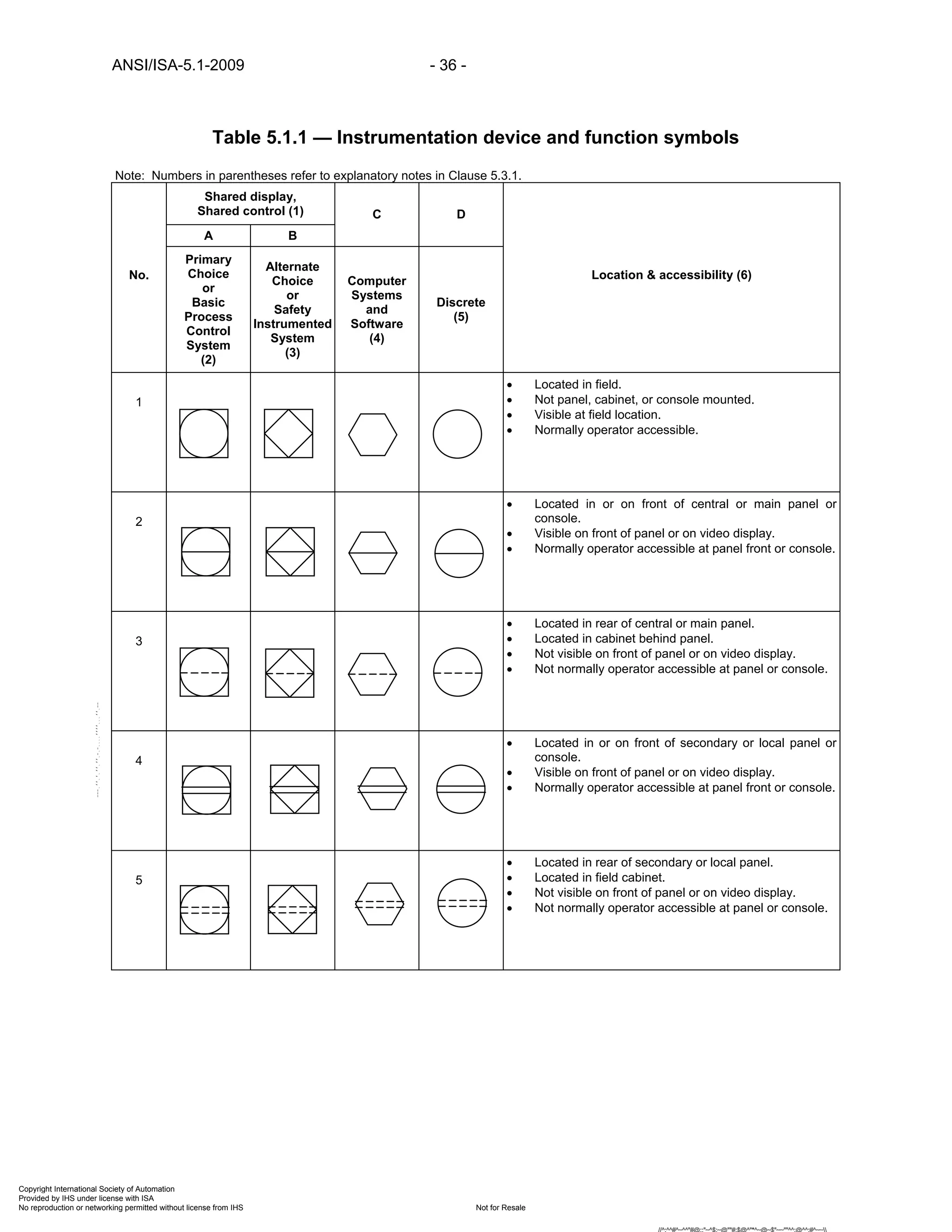
(7) Functions represented by these symbols are used for simple interlock logic:
(a) A description of the logic should be shown nearby or in the notes section of the drawing
or sketch if the intended logic is not clearly understandable.
(b) These symbols are not recommended for depicting complex DCS, PLC, or SIS
applications that require other than ‘AND’ and ‘OR’ signal gates.
(8) A logic number, letter, or number/letter combination identification shall be used if more than one
logic scheme is used on the project by:
(a) Replacing [I], [A], and [O] with the logic identification.
(b) Appending the logic identification outside the symbol.
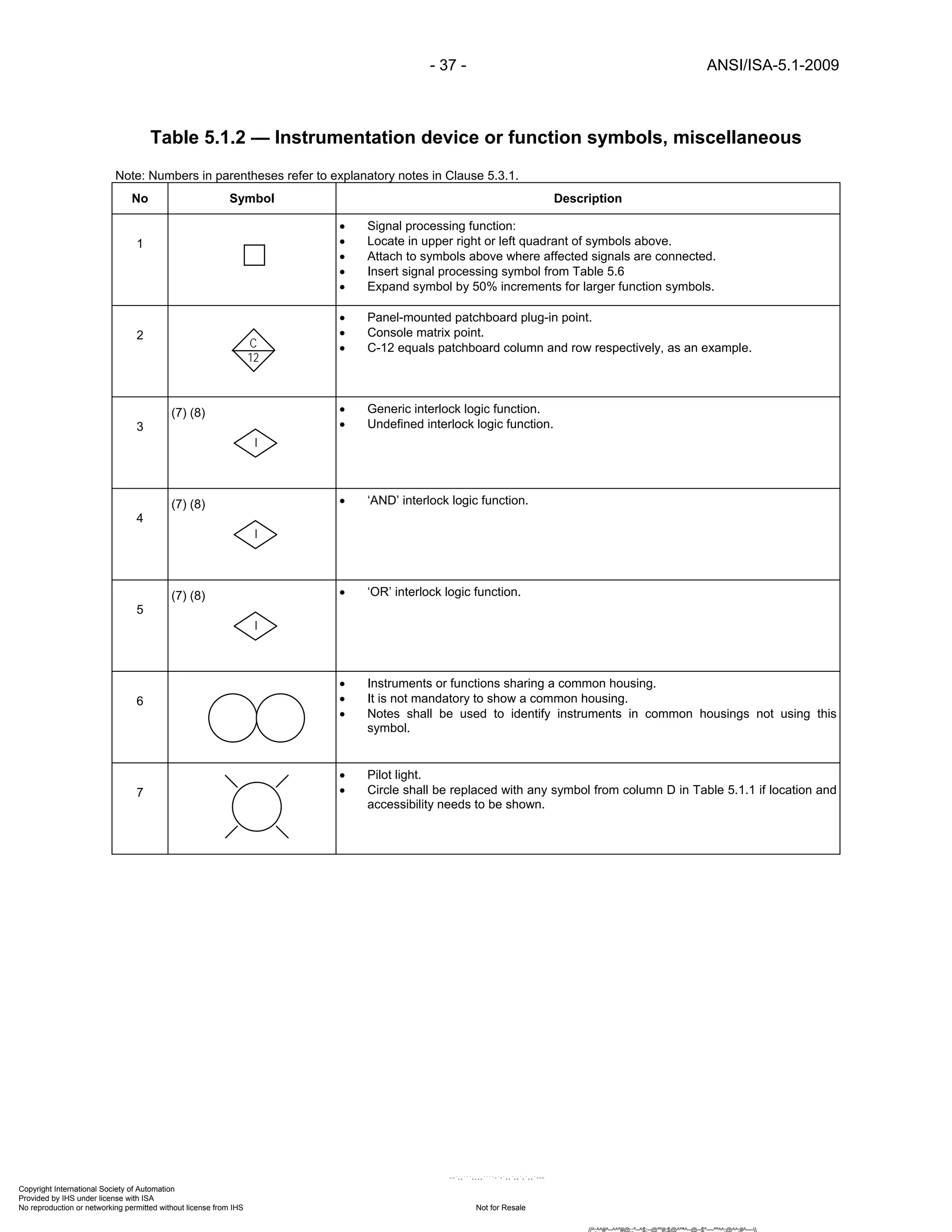
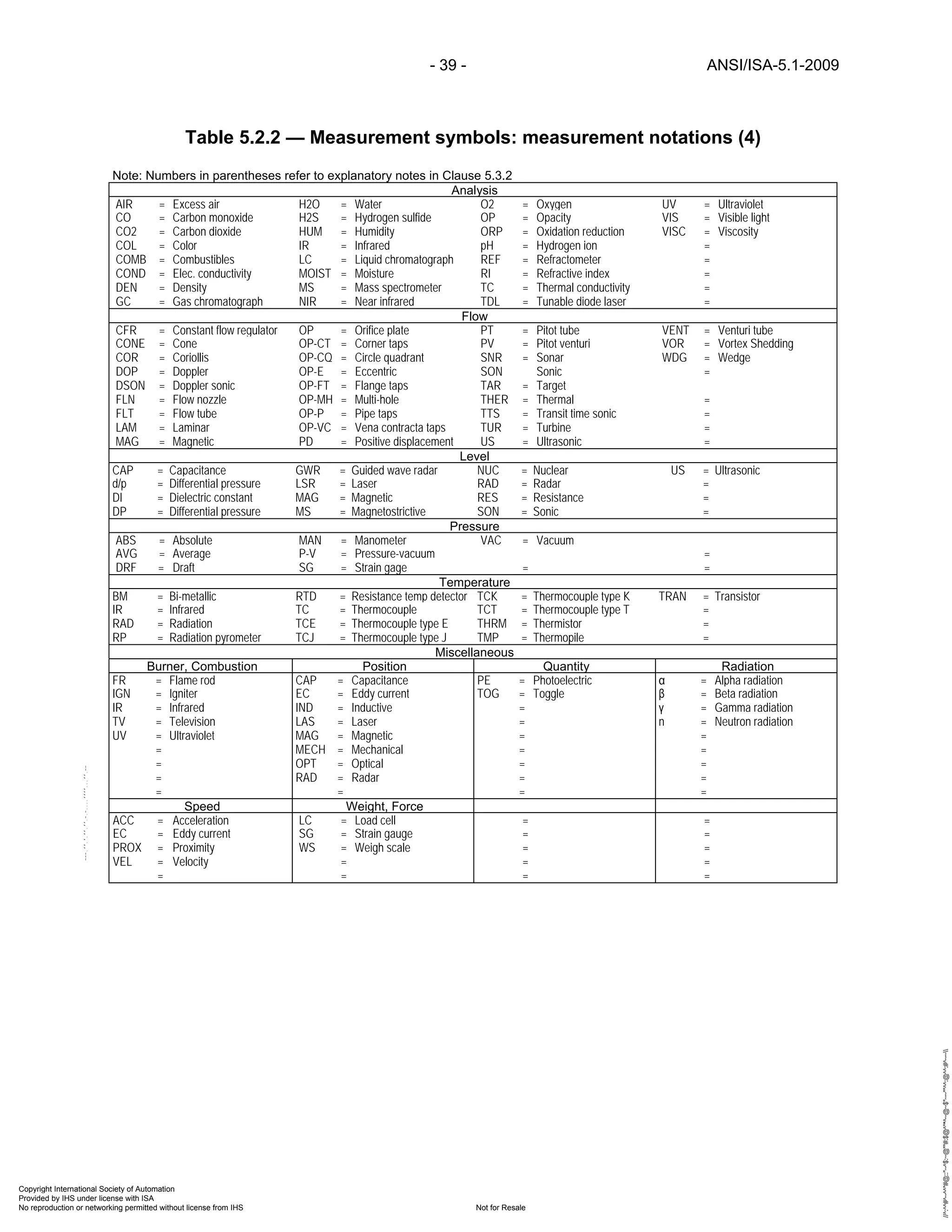
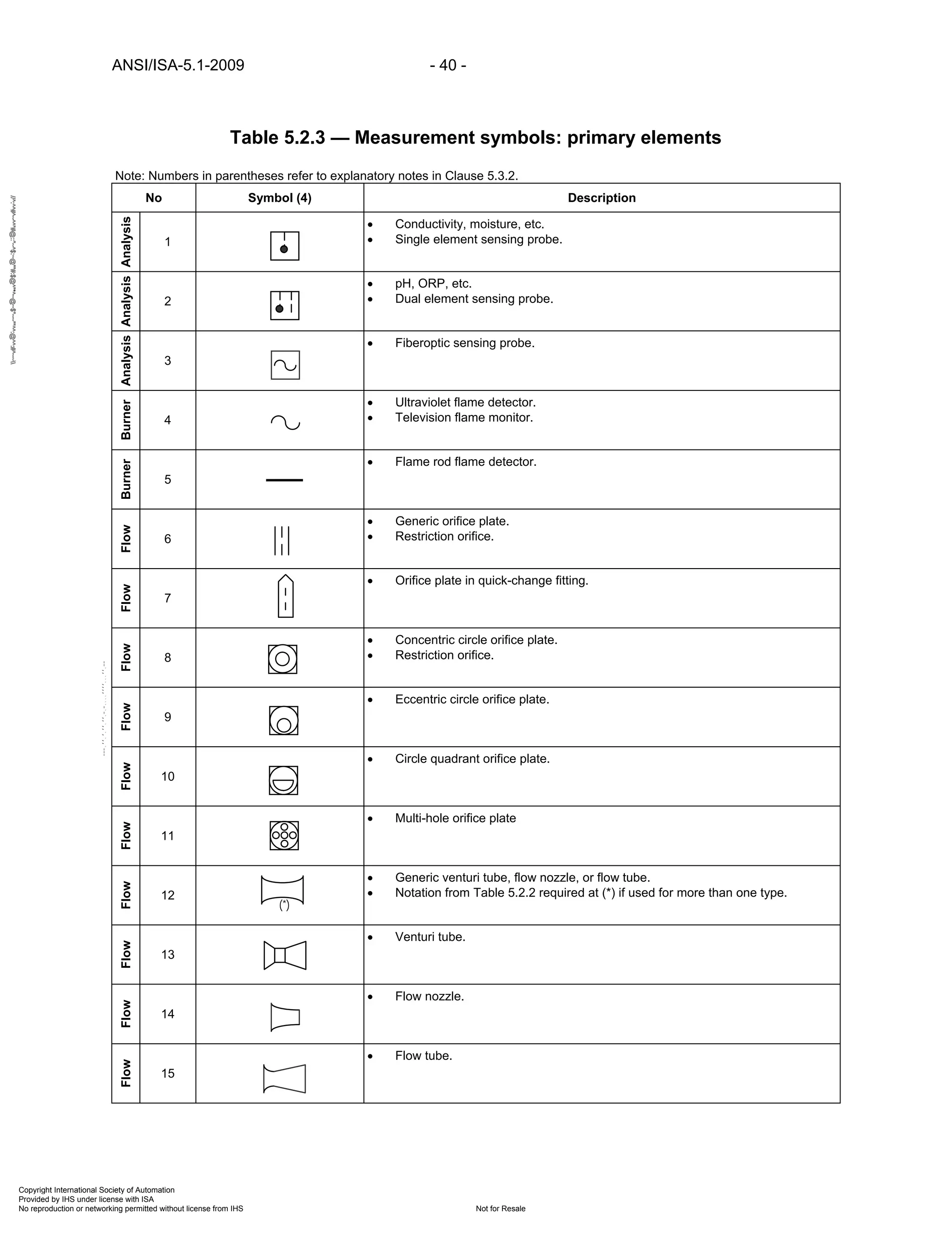
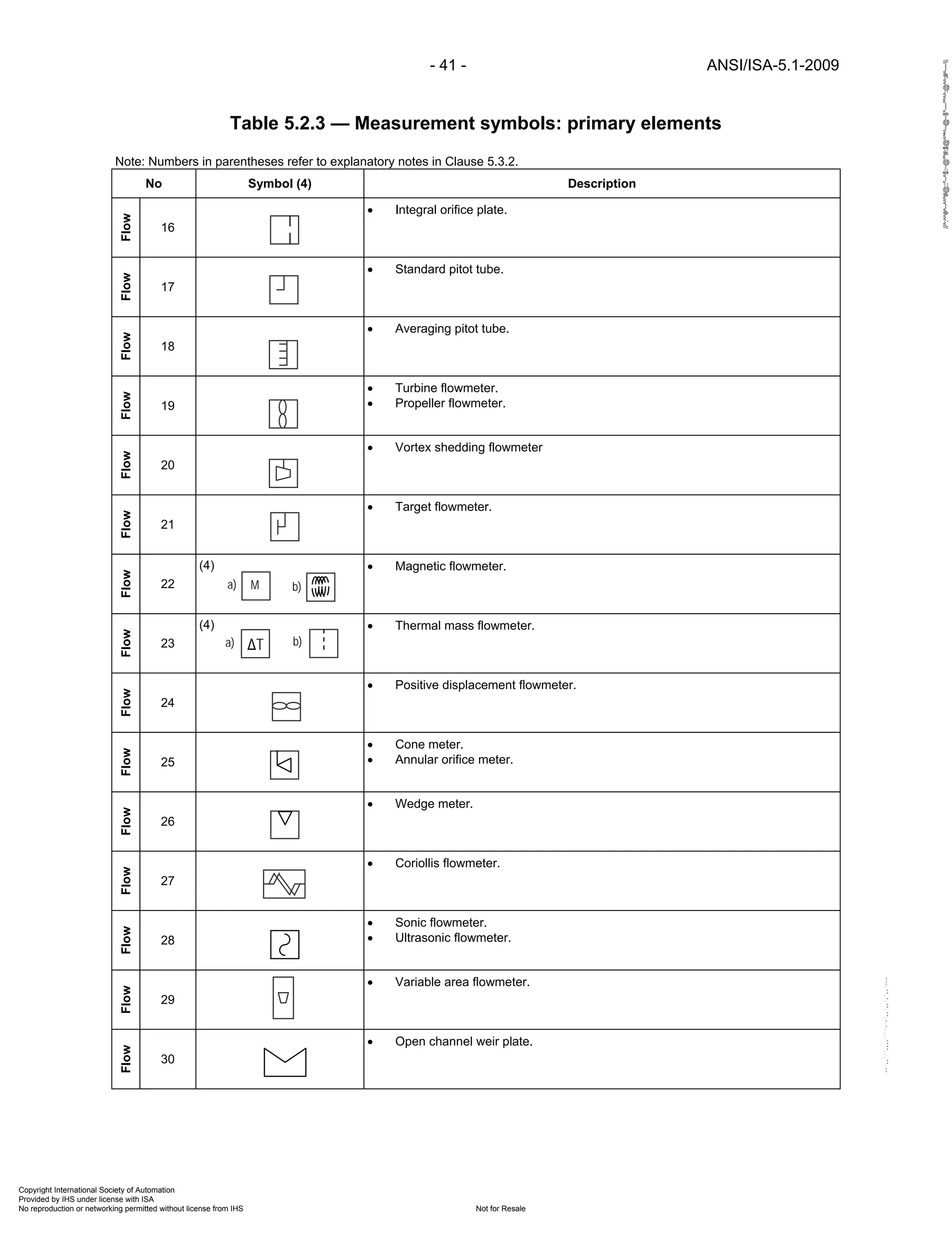
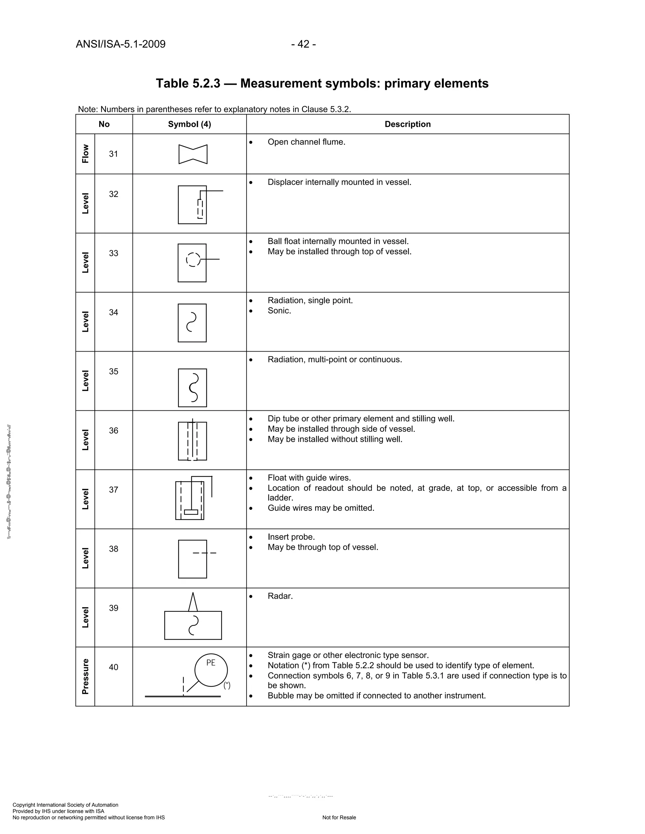
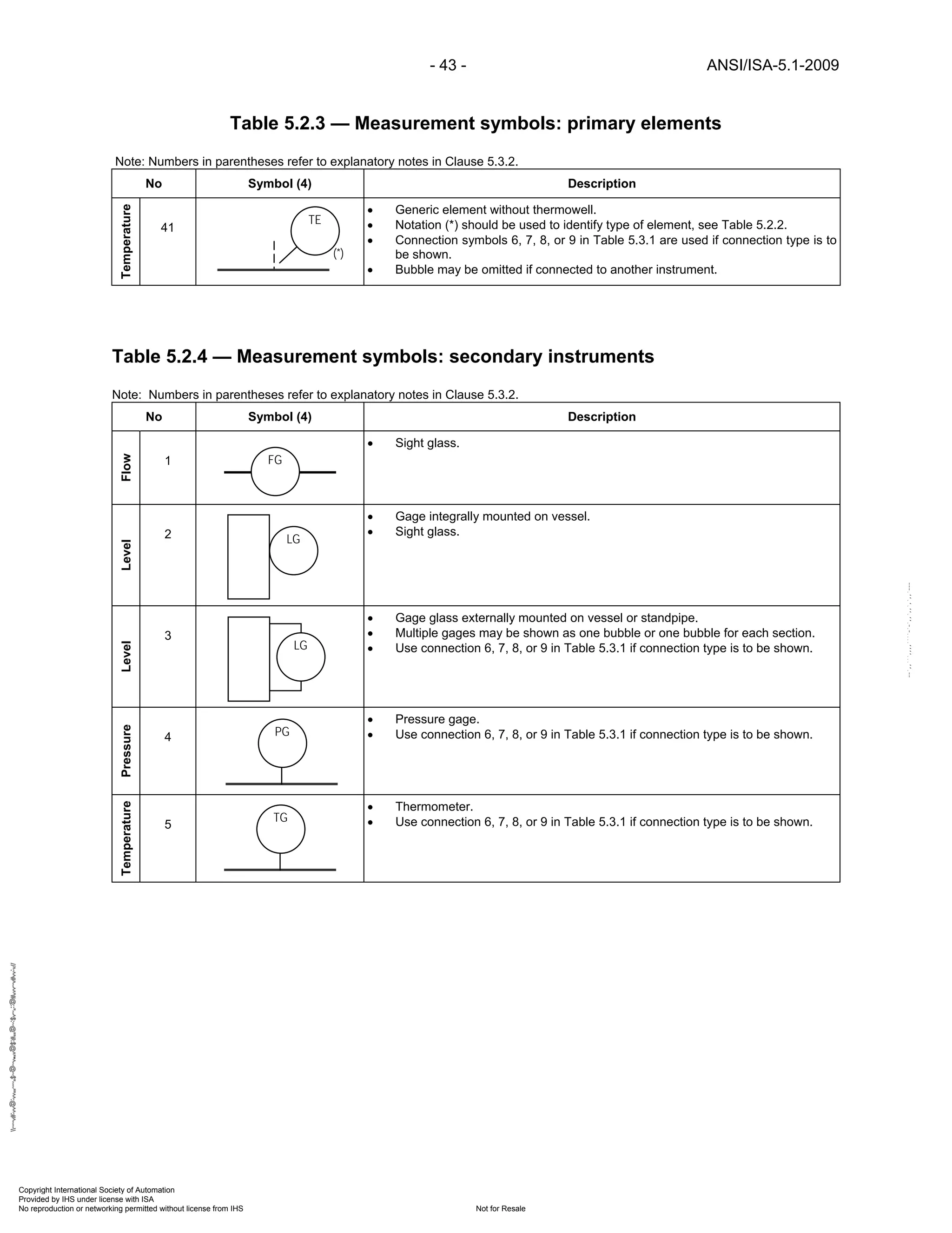
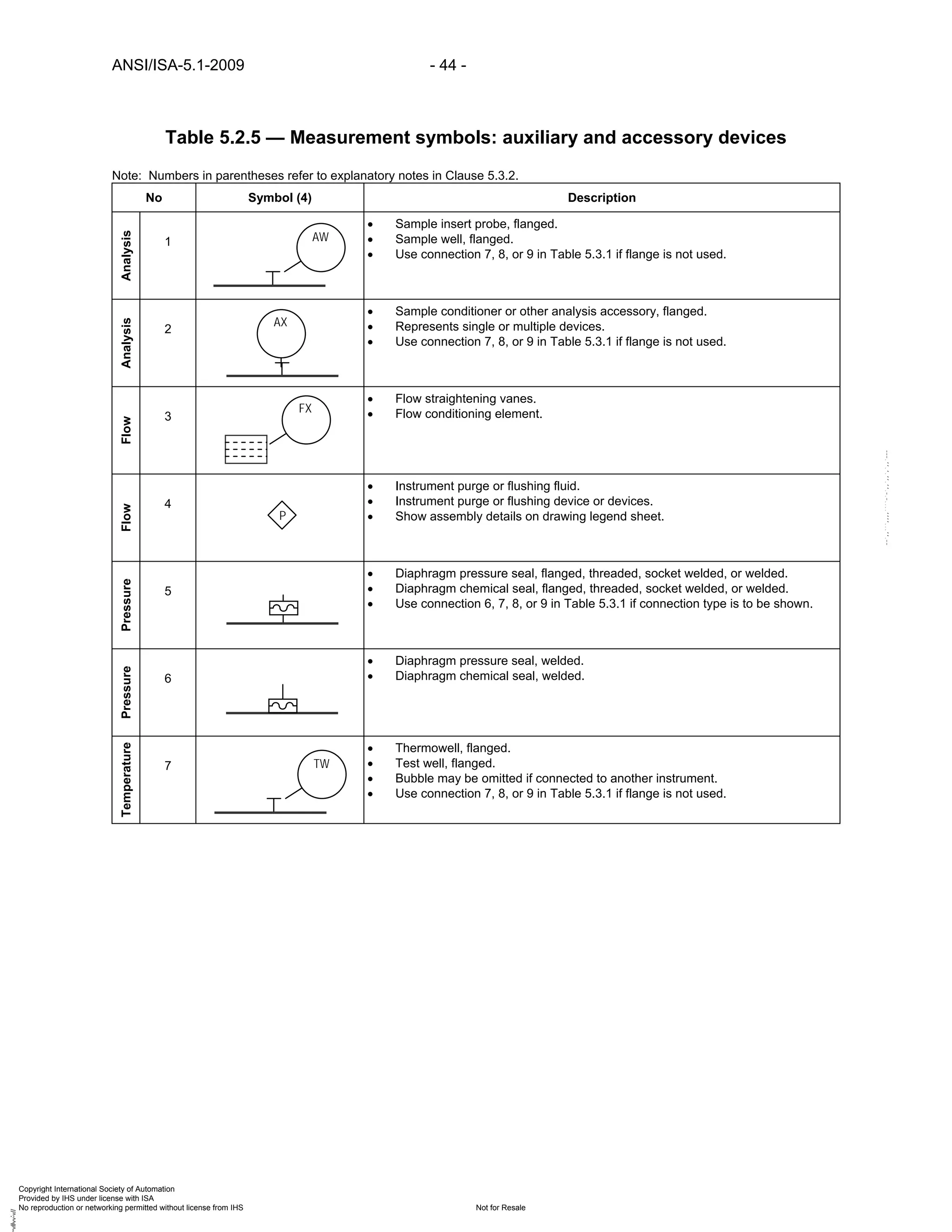
5.3.2 Tables 5.2.1, 5.2.2, 5.2.3, 5.2.4, and 5.2.5 — Measurement symbols
(1) Measurements are depicted by:
(a) Bubbles only.
(b) Bubbles and graphics.
(2) These symbols shall be used for process or equipment measurements if:
(a) A graphic symbol does not exist.
(b) The user does not use graphic symbols.
(3) Transmitter [T] may be controller [C], indicator [I], recorder [R], or switch [S].
(4) User engineering and design standards, practices, and/or guidelines shall document which
choices are selected.
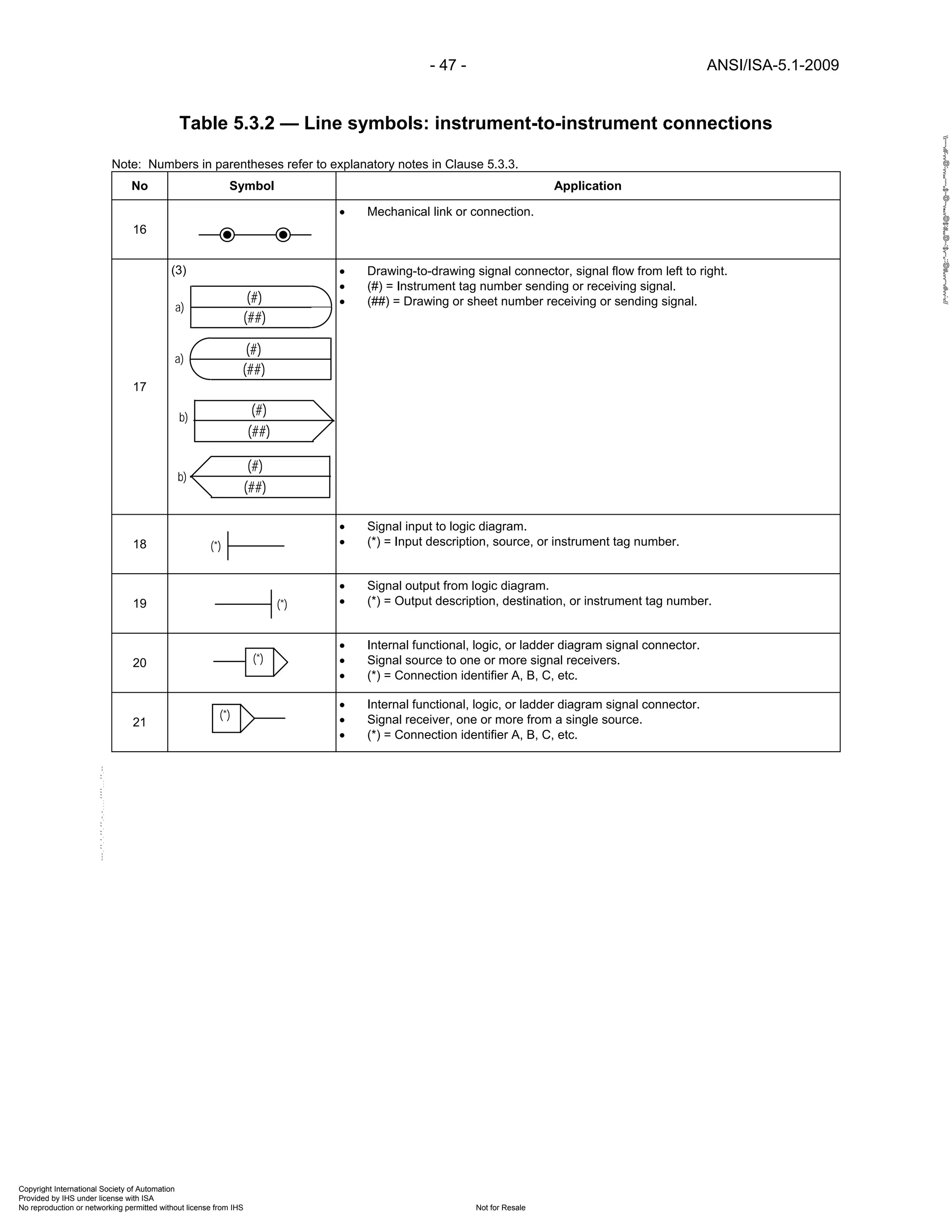
5.3.3 Tables 5.3.1 and 5.3.2 — Line symbols:
(1) Power supplies shall be shown when:
(a) Different from those normally used, e.g., 120 Vdc when normal is 24 Vdc.
(b) When a device requires an independent power supply.
Copyright International Society of Automation
Provided by IHS under license with ISA
Not for ResaleNo reproduction or networking permitted without license from IHS
--`,,```,,,,````-`-`,,`,,`,`,,`---
//^:^^#^~^^"#@::"~^$:~@""#:$@^"*^~@~$"~~""^^:@^^:#^~~](https://image.slidesharecdn.com/instrumentationsymbolsandidentification-200628175106/75/Instrumentation-symbols-and_identification-33-2048.jpg)

![- 45 - ANSI/ISA-5.1-2009
Table 5.3.1 — Line symbols: instrument to process and equipment connections
Note: Numbers in parentheses refer to explanatory notes in Clause 5.3.3.
No Symbol Application
1
• Instrument connections to process and equipment.
• Process impulse lines.
• Analyzer sample lines.
2
• Heat [cool] traced impulse or sample line from process.
• Type of tracing indicated by: [ET] electrical, [ST] steam, [CW] chilled water, etc.
3
• Generic instrument connection to process line.
• Generic instrument connection to equipment.
4
• Heat [cool] traced generic instrument impulse line.
• Process line or equipment may or may not be traced.
5
• Heat [cool] traced instrument.
• Instrument impulse line may or may not be traced.
6
• Flanged instrument connection to process line.
• Flanged instrument connection to equipment.
7
• Threaded instrument connection to process line.
• Threaded instrument connection to equipment.
8
• Socket welded instrument connection to process line.
• Socket welded instrument connection to equipment.
9
• Welded instrument connection to process line.
• Welded instrument connection to equipment.
(ST)
Copyright International Society of Automation
Provided by IHS under license with ISA
Not for ResaleNo reproduction or networking permitted without license from IHS
--`,,```,,,,````-`-`,,`,,`,`,,`---
//^:^^#^~^^"#@::"~^$:~@""#:$@^"*^~@~$"~~""^^:@^^:#^~~](https://image.slidesharecdn.com/instrumentationsymbolsandidentification-200628175106/75/Instrumentation-symbols-and_identification-45-2048.jpg)
![ANSI/ISA-5.1-2009 - 46 -
Table 5.3.2 — Line symbols: instrument-to-instrument connections
Note: Numbers in parentheses refer to explanatory notes in Clause 5.3.3.
No Symbol Application
1
(1) • IA may be replaced by PA [plant air], NS [nitrogen}, or GS [any gas supply].
• Indicate supply pressure as required, e.g., PA-70 kPa, NS-150 psig, etc.
2
(1) • Instrument electric power supply.
• Indicate voltage and type as required, e.g. ES-220 Vac.
• ES may be replaced by 24 Vdc, 120 Vac, etc.
3
(1) • Instrument hydraulic power supply.
• Indicate pressure as required, e.g., HS-70 psig.
4
(2) • Undefined signal.
• Use for Process Flow Diagrams.
• Use for discussions or diagrams where type of signal is not of concern.
5
(2) • Pneumatic signal, continuously variable or binary.
6
(2) • Electronic or electrical continuously variable or binary signal.
• Functional diagram binary signal.
7
(2) • Functional diagram continuously variable signal.
• Electrical schematic ladder diagram signal and power rails.
8
(2) • Hydraulic signal.
9
(2) • Filled thermal element capillary tube.
• Filled sensing line between pressure seal and instrument.
10
(2) • Guided electromagnetic signal.
• Guided sonic signal.
• Fiber optic cable.
11
(3) • Unguided electromagnetic signals, light, radiation, radio, sound, wireless, etc.
• Wireless instrumentation signal.
• Wireless communication link.
12
(4) • Communication link and system bus, between devices and functions of a shared
display, shared control system.
• DCS, PLC, or PC communication link and system bus.
13
(5) • Communication link or bus connecting two or more independent microprocessor or
computer-based systems.
• DCS-to-DCS, DCS-to-PLC, PLC-to-PC, DCS-to-Fieldbus, etc. connections.
14
(6) • Communication link and system bus, between devices and functions of a fieldbus
system.
• Link from and to “intelligent” devices.
15
(7) • Communication link between a device and a remote calibration adjustment device or
system.
• Link from and to “smart” devices.
IA
ES
HS
a)
b)
Copyright International Society of Automation
Provided by IHS under license with ISA
Not for ResaleNo reproduction or networking permitted without license from IHS
--`,,```,,,,````-`-`,,`,,`,`,,`---
//^:^^#^~^^"#@::"~^$:~@""#:$@^"*^~@~$"~~""^^:@^^:#^~~](https://image.slidesharecdn.com/instrumentationsymbolsandidentification-200628175106/75/Instrumentation-symbols-and_identification-46-2048.jpg)

![ANSI/ISA-5.1-2009 - 56 -
Table 5.5 — Functional diagramming symbols
Note: Numbers in parentheses refer to explanatory notes in Clause 5.3.5.
No Symbol (1) (2) Description
1
• Measuring, input, or readout device.
• [*] = Instrument tag number.
• Symbols from Table 5.2.1 may be used.
2
(3) (4) • Automatic single-mode controller.
3
(3) (4) • Automatic two-mode controller.
4
(3) (4) • Automatic three-mode controller.
5
(3) (4) • Automatic signal processor.
6
(4) • Manual signal processor.
7
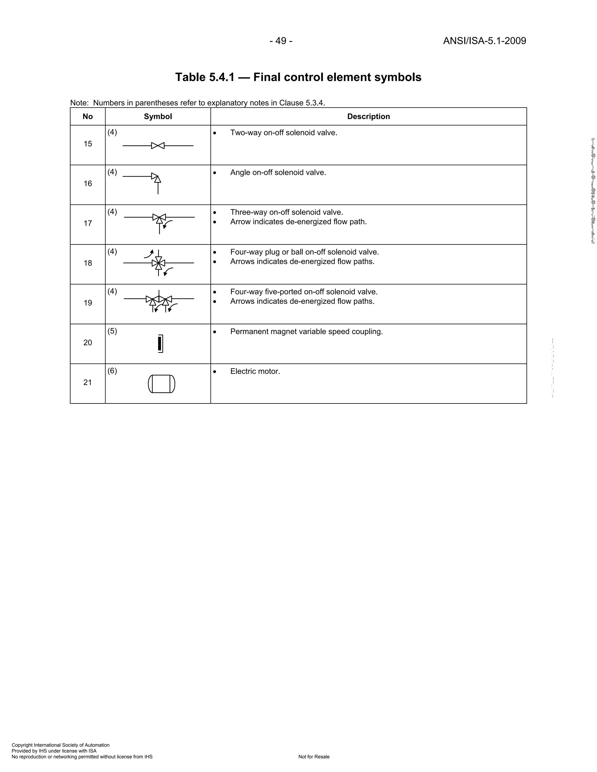
(3) (4) • Final control element.
• Control valve.
8
(3) (4) • Final control element with positioner.
• Control valve with positioner.
[*]
(*)
(*)
(*)
(*) (*)
(*)
(*) (*) (*)
(*)
(*)
(*)
(*)
Copyright International Society of Automation
Provided by IHS under license with ISA
Not for ResaleNo reproduction or networking permitted without license from IHS
--`,,```,,,,````-`-`,,`,,`,`,,`---
//^:^^#^~^^"#@::"~^$:~@""#:$@^"*^~@~$"~~""^^:@^^:#^~~](https://image.slidesharecdn.com/instrumentationsymbolsandidentification-200628175106/75/Instrumentation-symbols-and_identification-56-2048.jpg)
![- 61 - ANSI/ISA-5.1-2009
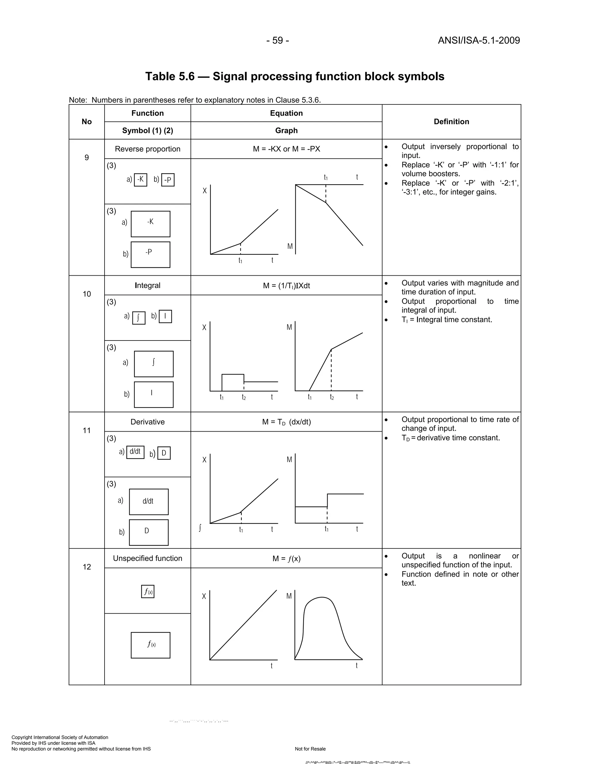
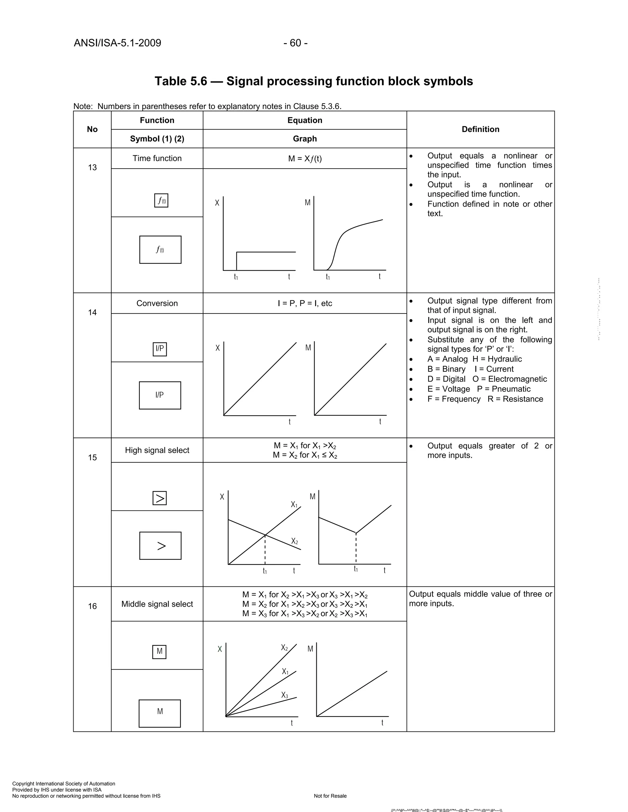
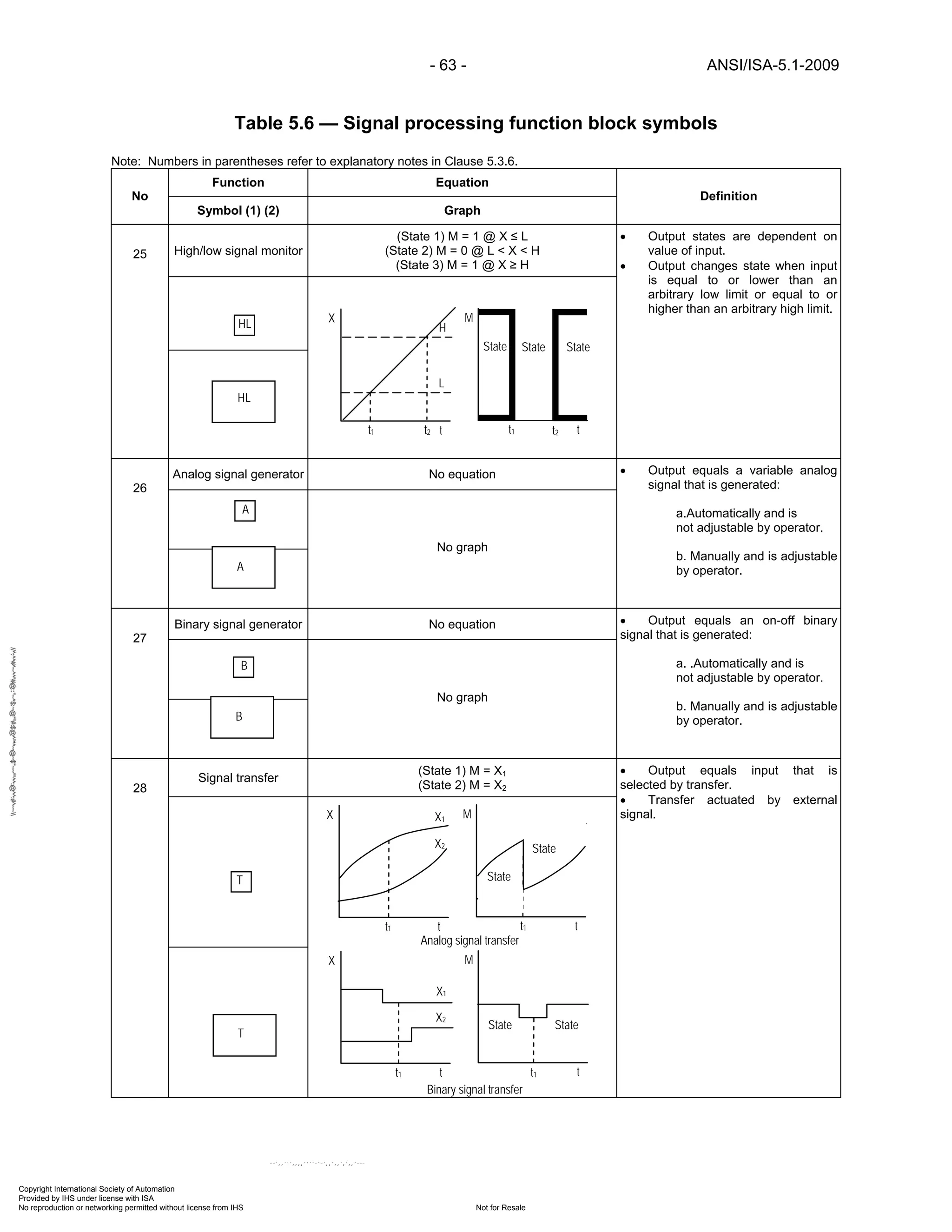
Table 5.6 — Signal processing function block symbols
Note: Numbers in parentheses refer to explanatory notes in Clause 5.3.6.
Function Equation
No
Symbol (1) (2) Graph
Definition
Low signal select
M = X1 for X1 ≤ X2
M = X2 for X1 ≥ X217
• Output equals lesser of 2 or more
inputs.
High limit
M = X for X ≤ H
M = H for X ≥ H18
• Output equals the lower of the
input or high limit values.
Low limit
M = X for X ≥ L
M = L for X ≤ L19
• Output equals the higher of the
input or low limit values.
Positive bias
M = X1 + b
M = [-]X2 + b20
• Output equal to input plus an
arbitrary value.
<
M
t
X
t t1
X1
t1
X2
<
>
X
tt1
H
M
tt1
<
+ X1X2 M
t
X
t
b
t1 t2 t1 t2
+
>
<
t1
L
X
t
M
tt1
Copyright International Society of Automation
Provided by IHS under license with ISA
Not for ResaleNo reproduction or networking permitted without license from IHS
--`,,```,,,,````-`-`,,`,,`,`,,`---
//^:^^#^~^^"#@::"~^$:~@""#:$@^"*^~@~$"~~""^^:@^^:#^~~](https://image.slidesharecdn.com/instrumentationsymbolsandidentification-200628175106/75/Instrumentation-symbols-and_identification-61-2048.jpg)
![ANSI/ISA-5.1-2009 - 62 -
Table 5.6 — Signal processing function block symbols
Note: Numbers in parentheses refer to explanatory notes in Clause 5.3.6.
Function Equation
No
Symbol (1) (2) Graph
Definition
Negative Bias
M = X1 - b
M = [-]X2 - b21
• Output equal to input minus an
arbitrary value.
Velocity limiter
dM/dt = dX/dt for dX/dt ≤ H, M = X
dM/dt = H for dX/dt ≥ H, M ≠ X
(3)
22
(3)
• Output equals input as long as the
input rate of change does not
exceed the limit value that
establishes the output rate of
change until the output again
equals the input.
High signal monitor
(State 1) M = 0 @ X < H
(State 2) M = 1 @ X ≥ H23
• Output state is dependent on
value of input.
• Output changes state when input
is equal to or higher than an
arbitrary high limit.
Low signal monitor
(State 1) M = 1 @ X ≤ L
(State 2) M = 0 @ X > L24
• Output state is dependent on
value of input.
• Output changes state when input
is equal to or lower than an
arbitrary low limit.
− M
t
X
t
b
X1X2
t1 t2 t1 t2
−
M
t
X
tt2,3t1
dX/dt>H dM/dt=H
t1 t2 t3
H
H
L
L
a)
b) >
b) >a)
t1
State State
M
t
X
t
H
t1
t1
State State
M
t
X
tt1
L
Copyright International Society of Automation
Provided by IHS under license with ISA
Not for ResaleNo reproduction or networking permitted without license from IHS
--`,,```,,,,````-`-`,,`,,`,`,,`---
//^:^^#^~^^"#@::"~^$:~@""#:$@^"*^~@~$"~~""^^:@^^:#^~~](https://image.slidesharecdn.com/instrumentationsymbolsandidentification-200628175106/75/Instrumentation-symbols-and_identification-62-2048.jpg)


![- 69 - ANSI/ISA-5.1-2009
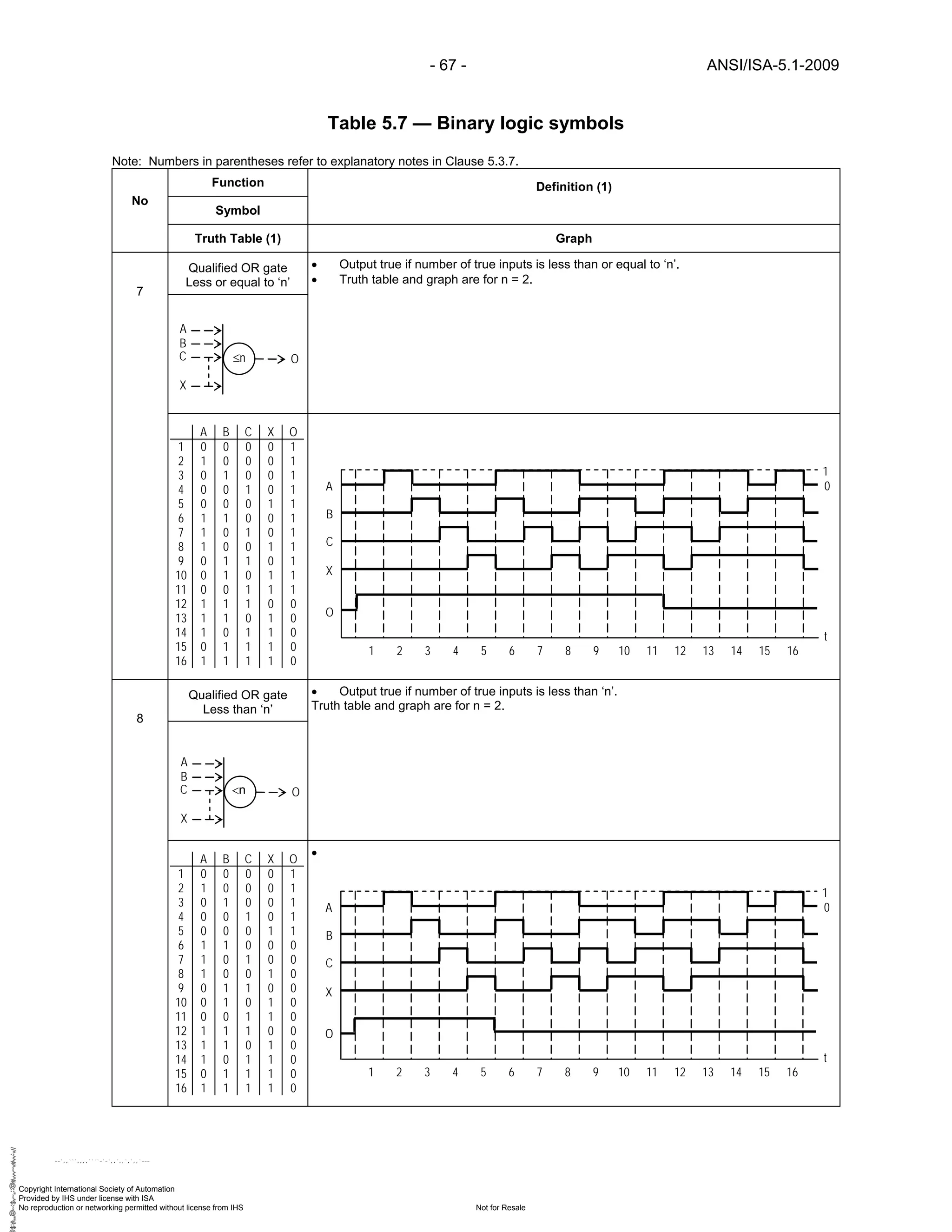
Table 5.7 — Binary logic symbols
Note: Numbers in parentheses refer to explanatory notes in Clause 5.3.7.
Function
Symbol
Definition (1)
No
Truth Table (1) Graph
NOT gate • Output false if input true.
• Output true if input false.
11
Basic memory • Outputs [C] and [D] are always opposite.
• If input [A] equals (1) then output [C] equals (1) and output [D] equals (0).
• If input [A] changes to (0) output [C] remains (1) until input [B] equals (1) then output [C]
equals (1) and output [D] equals (0).
• If input [B] equals (1) then output [D] equals (1) and output [C] equals (0).
• If input [B] changes to (0) output [D] remains (1) until input [A] equals (1), then output [D]
equals (1) and output [C] equals (0).
• If inputs [A] and [B] are simultaneously equal to (1) then outputs [C] and [D] change state.
12
Set dominant memory • Outputs [C] and [D] are always opposite.
• If input [A] equals (1) then output [C] equals (1) and output [D] equals (0).
• If input [A] changes to (0) output [C] remains (1) until input [B] equals (1) then output [C]
equals (1) and output [D] equals (0).
• If input [B] equals (1) then output [D] equals (1) and output [C] equals (0).
• If input [B] changes to (0) output [D] remains (1) until input [A] equals (1), then output [D]
equals (1) and output [C] equals (0).
• If inputs [A] and [B] are simultaneously equal to (1) then output [C] equals (1) and output
[D] equals (0).
13
A ONOT
A O
1 0
0 1
A
O
1 2 3 4 5 6 7 8 9 10 11 12 13 14 15 16
1
0
1
0
t
A
B
C
D
S
R
A B C D
1 0 0 0 1
2 1 0 1 0
3 0 0 1 0
4 0 1 0 1
5 0 0 0 1
6 1 1 1 0
7 0 0 1 0
8 1 1 0 1
A
B
C
D
t
1
0
1 2 3 4 5 6 7 8
A
B
C
D
So
R
A B C D
1 0 0 0 1
2 1 0 1 0
3 0 0 1 0
4 0 1 0 1
5 0 0 0 1
6 1 1 1 0
7 0 0 1 0
8 1 1 1 0 t
1
0
1 2 3 4 5 6 7 8
A
B
C
D
Copyright International Society of Automation
Provided by IHS under license with ISA
Not for ResaleNo reproduction or networking permitted without license from IHS
--`,,```,,,,````-`-`,,`,,`,`,,`---
//^:^^#^~^^"#@::"~^$:~@""#:$@^"*^~@~$"~~""^^:@^^:#^~~](https://image.slidesharecdn.com/instrumentationsymbolsandidentification-200628175106/75/Instrumentation-symbols-and_identification-69-2048.jpg)
![ANSI/ISA-5.1-2009 - 70 -
Table 5.7 — Binary logic symbols
Note: Numbers in parentheses refer to explanatory notes in Clause 5.3.7.
Function
Symbol
Definition (1)
No
Truth Table (1) Graph
Reset dominant memory • Outputs [C] and [D] are always opposite.
• If input [A] equals (1) then output [C] equals (1) and output [D] equals (0).
• If input [A] changes to (0) output [C] remains (1) until input [B] equals (1) then output [C]
equals (1) and output [D] equals (0).
• If input [B] equals (1) then output [D] equals (1) and output [C] equals (0).
• If input [B] changes to (0) output [D] remains (1) until input [A] equals (1), then output [D]
equals (1) and output [C] equals (0).
• If inputs [A] and [B] are simultaneously equal to (1) then output [C] equals (0) and output
[D] equals (1).
14
Pulse duration - fixed • Output [O] changes from (0) to (1) and remains (1) for prescribed time duration (t) when
input [I] changes from (0) to (1).
15
NONE
Time delay - off • Output [O] changes from (0) to (1) when input [I] changes from (0) to (1).
• Output [O] changes from (1) to (0) after input [I] changes from (1) to (0) and has been
equal to (0) for time duration (’t).16
NONE
A
B
C
D
S
Ro
A B C D
1 0 0 0 1
2 1 0 1 0
3 0 0 1 0
4 0 1 0 1
5 0 0 0 1
6 1 1 0 1
7 0 0 0 1
8 1 1 0 1 t
1
0
1 2 3 4 5 6 7 8
A
B
C
D
t PD OI
t t
1
0I
O
t
t DT OI
1
0I
O
t
t t
Copyright International Society of Automation
Provided by IHS under license with ISA
Not for ResaleNo reproduction or networking permitted without license from IHS
--`,,```,,,,````-`-`,,`,,`,`,,`---
//^:^^#^~^^"#@::"~^$:~@""#:$@^"*^~@~$"~~""^^:@^^:#^~~](https://image.slidesharecdn.com/instrumentationsymbolsandidentification-200628175106/75/Instrumentation-symbols-and_identification-70-2048.jpg)
![- 71 - ANSI/ISA-5.1-2009
Table 5.7 — Binary logic symbols
Note: Numbers in parentheses refer to explanatory notes in Clause 5.3.7.
Function
Symbol
Definition (1)
No
Truth Table (1) Graph
Time delay - on • Output [O] changes from (0) to (1) after input [I] changes from (0) to (1) and [I] remains (1)
for prescribed time duration (t).
• Output [O] remains (1) until Input [I] changes to (0) or optional Reset [R] changes to (1).17
NONE
Pulse duration - variable • Output [O] changes from (0) to (1) when input [I] changes from (0) to (1).
• Output [O] changes from (1) to (0) when Input [I] has been equal to (1) for time duration (t),
Input [I] changes from (1) to (0), or optional Reset [R] changes to (1).18
NONE
t GT OI
R
t tt
1
0I
O
t
R
t LT OI
R
1
0I
O
t
R
t t t
Copyright International Society of Automation
Provided by IHS under license with ISA
Not for ResaleNo reproduction or networking permitted without license from IHS
--`,,```,,,,````-`-`,,`,,`,`,,`---
//^:^^#^~^^"#@::"~^$:~@""#:$@^"*^~@~$"~~""^^:@^^:#^~~](https://image.slidesharecdn.com/instrumentationsymbolsandidentification-200628175106/75/Instrumentation-symbols-and_identification-71-2048.jpg)
![ANSI/ISA-5.1-2009 - 78 -
Table 6.1 — Dimensions for Tables 5.1.1 and 5.1.2
Note: Numbers in parentheses refer to explanatory notes in Clause 6.3.1.
7[8] (1)
7[8] (1)
2[2.5] (1)
0.5
1
7
9
5.5
2
2
1
3
4.5
6
6
4
6
Copyright International Society of Automation
Provided by IHS under license with ISA
Not for ResaleNo reproduction or networking permitted without license from IHS
--`,,```,,,,````-`-`,,`,,`,`,,`---
//^:^^#^~^^"#@::"~^$:~@""#:](https://image.slidesharecdn.com/instrumentationsymbolsandidentification-200628175106/75/Instrumentation-symbols-and_identification-78-2048.jpg)
![- 79 - ANSI/ISA-5.1-2009
Table 6.2 — Dimensions for Tables 5.2.1, 5.2.2, 5.2.3, 5.2.4, and 5.2.5
Note: Numbers in parentheses refer to explanatory notes in Clause 6.3.2.
7[8] (1)
4
64
1.5
0.5
4
2 3
1
1.25
1.25
2
5
11
4
2
1.5
1
6
1.5
2
6
2
4
2 4
6
2
1
2
3.53
1
3
2
1
1.5
3 5
2
2
2
2
1
2
1
2
4
1
12
2
3
2
3
1.5
1.5
0.75
6
2
2
4
6
2
6
0.5
1
0.67
1
6
1.5
1.5
•
5
2
4
7 3
5
6
1
4
4
7
2
1
2
(3)
(2)
4
1
3
4
4
Copyright International Society of Automation
Provided by IHS under license with ISA
Not for ResaleNo reproduction or networking permitted without license from IHS
--`,,```,,,,````-`-`,,`,,`,`,,`---
//^:^^#^~^^"#@::"~^$:~@""#:$@^"*^~@~$"~~""^^:@^^:#^~~](https://image.slidesharecdn.com/instrumentationsymbolsandidentification-200628175106/75/Instrumentation-symbols-and_identification-79-2048.jpg)
![ANSI/ISA-5.1-2009 - 80 -
Table 6.3 — Dimensions for Tables 5.3.1 and 5.3.2
Note: Numbers in parentheses refer to explanatory notes in Clause 6.3.3.
0.4 (2)
4
6
As req’d
Min = 1
Max = 1.5
Min = 0.5
Max = 0.75
1 11
2
2
1
6
Max = 16
Min = 8
Max = 16
Min = 8
0.2 (1)
Min = 8
Max = 32
2
2
1 1
2
2
4
2
4
0.5 (3)
1
0.5
1 1
0.5
2
Min = 1
Max = 1.5
Min = 0.5
Max = 0.75
1
1.5(ST)
9[10]Xt
7[8] (1)
Copyright International Society of Automation
Provided by IHS under license with ISA
Not for ResaleNo reproduction or networking permitted without license from IHS
--`,,```,,,,````-`-`,,`,,`,`,,`---
//^:^^#^~^^"#@::"~^$:~@""#:$@^"*^~@~$"~~""^^:@^^:#^~~](https://image.slidesharecdn.com/instrumentationsymbolsandidentification-200628175106/75/Instrumentation-symbols-and_identification-80-2048.jpg)


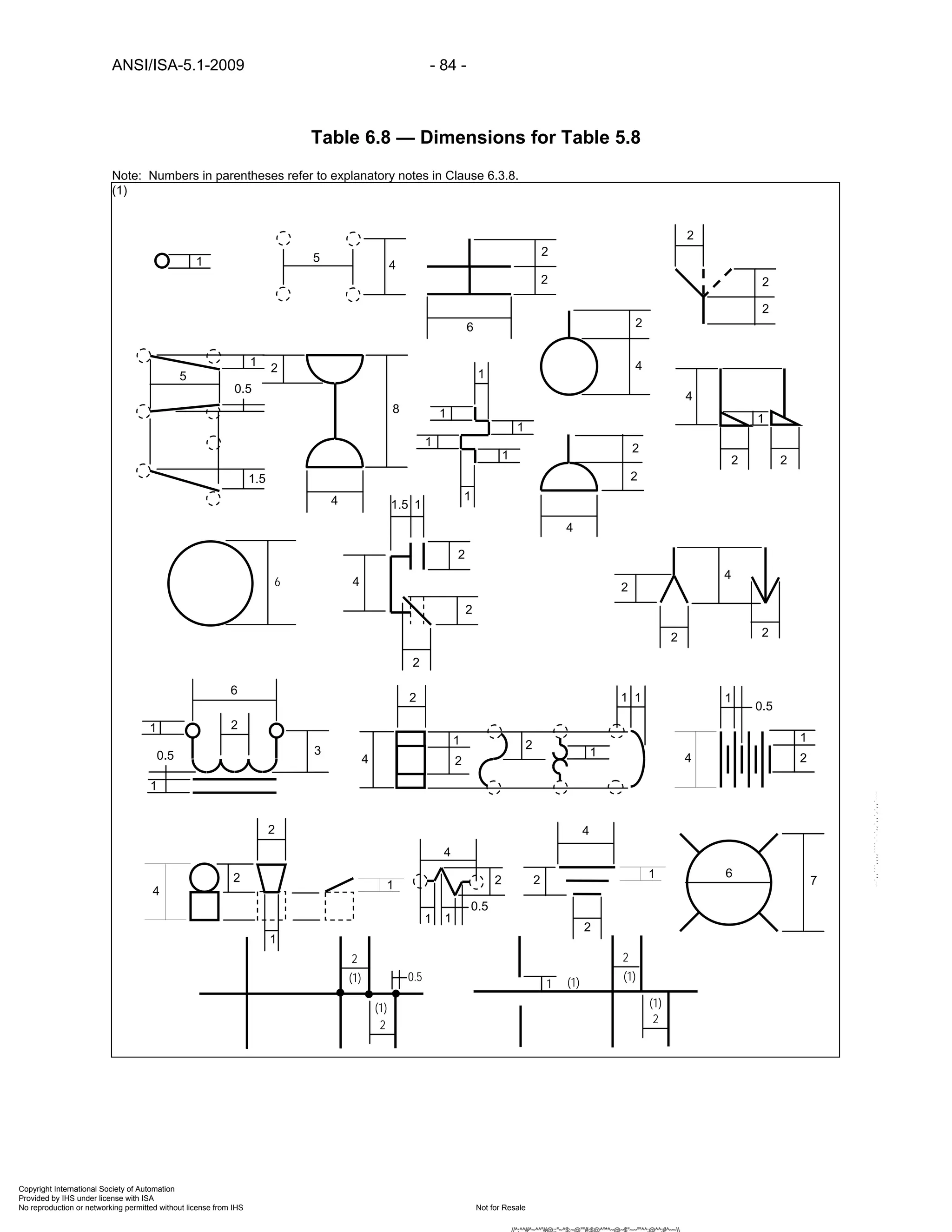
![ANSI/ISA-5.1-2009 - 88 -
b) Numerals to form a unique loop identity.
c) Optional loop suffixes to identify identical loops on identical pieces of equipment or
services.
A.5 Loop identification number letters
A.5.1 Loop Identification Number letters should be selected from Table 4.1 to identify the loop
Measured/Initiating Variable according to one of the following methods selected by the end user:
a) Measured/Initiating Variable: only a Measured/Initiating Variable is selected, such as
analysis [A], flow [F], level [L], pressure [P], temperature [T], etc.
b) Measured/Initiating Variable with Variable Modifier: a Measured/Initiating Variable and,
when applicable, a Variable Modifier is selected, such as analysis [A], flow [F], flow quantity
[FQ], level [L], pressure [P], differential pressure [PD], temperature [T], differential temperature
[TD], etc.
c) First-Letters: a Measured/Initiating Variable and, when applicable, a Variable Modifier,
only if the resulting First-Letter combination defines a loop variable that can be measured
directly, such as pressure differential [PD] as opposed to one that is mathematically derived,
such as flow ratio [FF].
A.5.2 A Measured/Initiating Variable in combination with the safety Variable Modifier [S] is always
treated as a loop variable in each of the preceding selection methods to identify self-acting
devices intended to protect against emergency conditions that may be hazardous to plant
personnel, plant equipment, or the environment.
A.5.3 A Measured/Initiating Variable is selected according to the physical or mechanical property that is
being measured, derived or initiates an action and not according to the construction or mode of
actuation of the measuring device or the property or the action it initiates:
a) A loop that controls pressure in a vessel by manipulating gas or vapor flow to or from the
vessel is a pressure [P] loop and not a flow [F] loop.
b) A loop that measures pressure differential across:
1) An orifice plate from which flow rate is calculated is a flow [F] loop and not a
pressure [P] or pressure differential [PD] loop.
2) A fluid interface in a vessel is a level [L] loop and not a pressure [P] or pressure
differential [PD] loop.
3) A filter bed or element is a pressure [P] or pressure differential [PD]-loop.
A.6 Loop identification number numerals
A.6.1 Loop Identification Number numerals should be assigned to loop measured variable letters
according to one of the following methods selected by the end user:
Copyright International Society of Automation
Provided by IHS under license with ISA
Not for ResaleNo reproduction or networking permitted without license from IHS
--`,,```,,,,````-`-`,,`,,`,`,,`---
//^:^^#^~^^"#@::"~^$:~@""#:$@^"*^~@~$"~~""^^:@^^:#^~~](https://image.slidesharecdn.com/instrumentationsymbolsandidentification-200628175106/75/Instrumentation-symbols-and_identification-88-2048.jpg)
![- 89 - ANSI/ISA-5.1-2009
a) Parallel: duplicated numerical sequences for each loop variable letter or first letter
combination.
b) Serial: single numerical sequence regardless of loop variable letter or first letter
combination.
c) Parallel/Serial: parallel sequences for selected loop variable letters or first letter
combinations and a serial sequence for the remainder.
A.6.2 Loop Number numerical sequences are normally three or more digits, -*01, -*001, -*0001, etc.
where the asterisk * can be :
a) Any digit from zero to 9.
b) Coded digits related to drawing numbers, unit numbers, equipment numbers, etc.
A.6.3 *00, *000, *0000, etc. should be used only for special, significant, or critical loops as defined by
the User.
A.6.4 000, 0000, 00000, etc. should not be used
A.6.5 Loop Identification letters and numbers should be assigned in accordance with one of the
following Loop Numbering Schemes:
a) No. 1 Parallel – Measured/Initiating Variable.
b) No. 2 Parallel – Measured/Initiating Variable with Variable Modifier.
c) No. 3 Parallel – First Letter(s).
d) No. 4 Series – Measured/Initiating Variable.
e) No. 5 Series – Measured/Initiating Variable with Variable Modifier.
f) No. 6 Series – First Letter(s).
g) No. 7 Parallel/Series – Measured/Initiating Variable.
h) No. 8 Parallel/Series – Measured/Initiating Variable with Variable Modifier.
i) No. 9 Parallel/Series – First Letter(s).
A.6.6 Gaps should be left in any sequence to allow for the addition of future loops.
A.6.7 See Table A.2 — Allowable letter/number combinations for, loop numbering schemes for
examples of typical Loop Number assignments.
A.7 Optional loop number prefixes
A.7.1 Loop Number Prefixes consisting of any combination of alpha/numeric characters that may be
added to Loop Numbers to identify loop location, such as a complex, plant, or unit should be
located before the Measured/Initiating Variable, for example, a flow loop in processing plant #1
might be [PP1-F*01].
Copyright International Society of Automation
Provided by IHS under license with ISA
Not for ResaleNo reproduction or networking permitted without license from IHS
--`,,```,,,,````-`-`,,`,,`,`,,`---
//^:^^#^~^^"#@::"~^$:~@""#:$@^"*^~@~$"~~""^^:@^^:#^~~](https://image.slidesharecdn.com/instrumentationsymbolsandidentification-200628175106/75/Instrumentation-symbols-and_identification-89-2048.jpg)
![ANSI/ISA-5.1-2009 - 90 -
A.7.2 Loop Number Prefixes should:
a) Not necessarily be shown on drawings or indexes but covered by a general note on a
legend sheet or a note on each drawing or index sheet.
b) Be shown for all uses on drawings when more than one prefix is required by loops shown
on the drawing.
c) Be shown when used in text.
A.8 Instrument identification/tag number
A.8.1 An Instrument Identification/Tag Number is a unique combination of letters and numbers that is
assigned to define the purpose of each loop device and/or function that comprises a monitoring or
control loop.
A.8.2 Adding a Variable Modifier, if needed, and Succeeding Letters to the Loop Identification Number
letters forms an Instrument Identification/Tag Number.
A.8.3 Instrument Identification/Tag Numbers may also be called Instrument Identification Number,
Instrument Tag Number, Instrument Number, or Tag Number.
A.9 Function identification letters
A.9.1 Instrument Function Identification letters should be selected from Table 4.1, Identification Letters,
and added to the Loop Identification Number letters to form an Instrument Functional Identity.
A.9.2 The sequence of letters in a Functional Identification should be in the same left-to-right order as
the columns in Table 4.1:
a) Measured or Initiating Variable, from Column 1.
b) Modifier, if required, from Column 2.
c) Passive Readout Function, from Column 3.
d) Active Output Function, from Column 4.
e) Modifier(s), if required, from Column 5.
A.9.3 Functional Identifications should use one Readout/Passive Function or one Output/Active
Function to identify each device or function except, as is common for:
a) Indicating /recording controller/switch instruments or functions in which one Passive
Function, indicate [I] or record [R] and one Active Function, control [C] or switch [S], is
combined to form, for example, pressure recording controller [PRC], or low-pressure indicating
switch [PISL].
b) Self-actuated control valves, in which two Active Functions control [C] and valve [V] are
combined to form, for example, pressure control valve [PCV].
Copyright International Society of Automation
Provided by IHS under license with ISA
Not for ResaleNo reproduction or networking permitted without license from IHS
--`,,```,,,,````-`-`,,`,,`,`,,`---
//^:^^#^~^^"#@::"~^$:~@""#:$@^"*^~@~$"~~""^^:@^^:#^~~](https://image.slidesharecdn.com/instrumentationsymbolsandidentification-200628175106/75/Instrumentation-symbols-and_identification-90-2048.jpg)
![- 91 - ANSI/ISA-5.1-2009
A.9.4 The number of letters in a Functional Identification should be sufficient to fully describe the
functionality of the device or function being identified, but generally should not exceed eight.
A.9.5 Function Modifiers designate the relative value of the measured or initiating variable that actuates
the instrument or function, for example for Function Modifier low [L]:
a) [PSL-*01] indicates actuation by a pressure below a setpoint, normally used to indicate a
process level that requires operator intervention to prevent a process trip or other unwanted
result.
b) [PSLL-*01] indicates actuation below a setpoint lower than the previous example,
normally used to indicate a process level that resulted in a process trip.
A.9.6 A device or function common to two or more loops should be assigned a Loop Identification Letter
for the loop which actuates the instrument:
a) A solenoid valve that is actuated by a high level switch [LSH] to trip a flow control valve
[FV] is assigned to the level [L] loop as an [LY] and not to the flow [F] loop as an [FY].
b) A high signal select device or function that selects the higher signal from a flow [F] loop
and a high level [L] override loop is assigned to the flow [F]-loop as an [FY] and not to the
level [L] loop as an [LY].
A.9.7 For allowable function letter combinations see tables:
a) A.3.1 — Allowable succeeding letter combinations for readout/passive function letters.
b) A.3.2 — Allowable succeeding letter combinations for output/active function letters.
A.10 Loop number and instrument/tag number suffixes
A.10.1 A Loop Number Suffix may be added to a Loop Number to identify identical loops on identical
equipment in the same processing unit when the service or equipment is assigned the same
equipment identification number with a suffix, such as reactors, heat exchangers, and pumps.
A.10.2 A Loop Suffix may use alphabetic or numeric characters according to User/Owner established
practice and should be located after the Loop Identification Number as illustrated in Table A.1.
A.10.3 A Loop Suffix may be located after the Loop Letters when user, owner, computer, or
microprocessor information systems will not allow alphabetic or additional numeric characters in
the numerical part of an identification number:
A.10.4 An Identification/Tag Number Suffix should be added to Instrument Identification/Tag Numbers in
the loop to designate two or more similar devices or functions:
a) Case 1 – in different services, such as control valves that direct flow to different places,
or auxiliary devices, such as those that perform different functions.
b) Case 2 – in the same service, such as control valves that direct flow to the same place,
or auxiliary devices, such as those that perform the same function.
A.10.5 Additional Identification/Tag Number Suffixes should be added when two or more similar devices
or functions are also duplicated, using alternating alpha/numeric characters.
Copyright International Society of Automation
Provided by IHS under license with ISA
Not for ResaleNo reproduction or networking permitted without license from IHS
--`,,```,,,,````-`-`,,`,,`,`,,`---
//^:^^#^~^^"#@::"~^$:~@""#:$@^"*^~@~$"~~""^^:@^^:#^~~](https://image.slidesharecdn.com/instrumentationsymbolsandidentification-200628175106/75/Instrumentation-symbols-and_identification-91-2048.jpg)
![ANSI/ISA-5.1-2009 - 92 -
A.10.6 For examples of Loop Number and Instrument/Tag Number Suffixes, see Table A.4.
A.11 Optional punctuation marks in identification numbers
A.11.1 Punctuation marks, hyphens, slashes, etc., may be used to separate sections of identification
numbers as required by:
a) User/Owner.
b) Database management system.
c) Control system application software.
A.11.2 Punctuation is recommended for use between:
a) An alphabetic Loop Number prefix and Measured/Initiating Variable letters: [AB-P*05].
b) Loop Number numerals and a numeric Loop Number suffix: [AB-P*05-1, AB-P*05-2],
c) Loop Number numerals and Tag Number suffix: [10-P*05-A1A or 10-P*05-1A1]
d) A Loop Number suffix and Tag Number suffix: [10PT*05A-A or 10PT*05-1-A].
A.11.3 Punctuation is optional for use between:
a) A Numeric Loop Number prefix and Measured/Initiating Variable letter: [10-P*05].
b) A Measured /Initiating Variable letter and Loop Number numerals: [10P*-05].
A.11.4 Punctuation should not be used between:
a) Loop Number numerals and an alphabetic Loop Number suffix: [10P*05A].
b) Additional Tag Number suffixes: [10PV*05A-A1A].
A.11.5 Backslashes are normally used between Functional Identification letters for multifunction devices
when used in text, [TR⁄TSH-*108].
A.12 Multivariable, multifunction, and multipoint loops
A.12.1 Loops that have more than one input and/or output are classified as:
a) Multivariable: when two or more Measured/Initiating Variables of the same or different
kinds generate one Output/Active Function and one or more Readout/Passive Functions.
b) Multifunction: when one Measured/Initiating Variable generates two or more
Output/Active or Readout/Passive Functions.
c) Multivariable/multifunction: when two or more Measured/Initiating Variables of the same
or different kinds generates two or more Output/Active or Readout/Passive Functions..
Copyright International Society of Automation
Provided by IHS under license with ISA
Not for ResaleNo reproduction or networking permitted without license from IHS
--`,,```,,,,````-`-`,,`,,`,`,,`---
//^:^^#^~^^"#@::"~^$:~@""#:$](https://image.slidesharecdn.com/instrumentationsymbolsandidentification-200628175106/75/Instrumentation-symbols-and_identification-92-2048.jpg)
![- 93 - ANSI/ISA-5.1-2009
d) Multipoint: when two or more Measured/Initiating Variables of the same or different kinds
generate two or more Readout/Passive Functions.
A.12.2 Multivariable Loop Number assignments using pressure [P-*07], temperature [T-*03], and speed
[S-*02] loops, for example, should be either:
a) Alphabetically ordered Measured/Initiating Variables with Loop Number numerals the
same as or different from the leading Measured/Initiating Variable: [PTS-*07] or [PTS-*10].
b) Multivariable Measured/Initiating Variable [U]: [U-*01]
A.12.3 Multivariable Loop components should be assigned Instrument/Tag Numbers as an example for:
a) Inputs: [PT-*07], [TT-*03], and [ST-*02].
b) Output: either [PTSV*07], [PTSV-*10], or [UV-*01].
A.12.4 Multifunction Instrument/Tag Number assignments using a flow [F] loop with indicating [I],
controlling [C], and switching [S] functions, for example, should be either [FICS-*05].or [FU-*05].
A.12.5 Multivariable/multifunction Loop Number assignments using flow [F-*05], pressure [P-*07],
temperature [T-*03], and speed [S-*02] loops, for example, should be either:
a) Alphabetically ordered Measured/Initiating Variables with Loop Number numerals the
same as or different from the leading Measured/Initiating Variable: [FPTS-*05] or [FPTS-*10].
b) Multivariable Measured/Initiating Variable [U]: [U-*01]
A.12.6 Multivariable/Multifunction Loop components should be assigned Instrument/Tag Numbers as an
example for:
a) Inputs: [FT-*05], [PT-*07], [TT-*03], and [ST-*02].
b) Output: either [PTSV*07] or [PTSV-*10], and [FV-*05], or [UV-*01A] and [UV-*01B].
A.12.7 Multipoint Loop and Instrument/Tag Number identification letter assignments for :
a) Single Measured/Initiating Variable, using temperature [T] as an example, should be:
1) Loop Number: [T-*11].
2) Input: [TE-*11-01], [TE-*11-02], etc. or [TJE]-*11-01, [TJE-*11-02], etc.
3) Readout: [TI-*11] or [TJI-*11]
4) Readout point; [TI-*11-01], [TI-*11-02], etc. [TJI-*11-01], [TJI-*11-02], etc.
b) Multiple Measured/Initiating Variables, using pressure [P] and temperature [T] as an
example, should be:
1) Loop Number: [PT-*11] or [U-*01].
2) Input: [PT-*11-01], [TE-*11-02], etc. or [PJT-*11-01], [TJE-*11-02], etc.
3) Readout: [PTI-*11] or [PTJI-01] or [UI-*01] or [UJI-*01].
Copyright International Society of Automation
Provided by IHS under license with ISA
Not for ResaleNo reproduction or networking permitted without license from IHS
--`,,```,,,,````-`-`,,`,,`,`,,`---
//^:^^#^~^^"#@::"~^$:~@""#:$@^"*^~@~$"~~""^^:@^^:#^~~](https://image.slidesharecdn.com/instrumentationsymbolsandidentification-200628175106/75/Instrumentation-symbols-and_identification-93-2048.jpg)
![ANSI/ISA-5.1-2009 - 94 -
4) Readout point: [PI-11-01], [TI-11-02], etc. or [PJI-11-01], [TJI-11-02], etc.
A.13 Secondary, auxiliary, and accessory instrumentation
A.13.1 Secondary instrumentation, such as level glasses, pressure gauges, and thermometers, may be
assigned either:
a) An Instrument Identification/Tag Number which should be either of:
1) LG-*01, PG-*01, TG-*01, etc.
2) LI-*01, PI-*01, TI-*01, etc.
b) A generic identification number that defines the instrument type and range which should
be either of:
1) LG-24 – 0-24in, PG-200 – 0-200psig, TG-250 – 0-250degF.
2) LI-24 – 0-24in, PI-200 – 0-200psig, TI-250 – 0-250degF.
A.13.2 Readout/Passive Function letter for glass, gauge, or viewing device [G] is recommended for use
for flow glasses [FG], level glasses or gauges [LG], pressure gauges [PG], thermometers [TG],
etc., to avoid database management problems with primary flow indicators [FI], level indicators
[LI], pressure indicators [PI], temperature indicators [TI], etc.
A.13.3 Current common usage is [FG] and [LG] for flow and level and [PI] and [TI] for pressure and
temperature.
A.13.4 Auxiliary instrumentation, such as signal computing and converting relays, solenoid valves, and
analyzer sample conditioning units, are identified by a loop Measured/Initiating Variable and the
Output/Active Function [Y], as in, [FY], [PY], etc.
A.13.5 Instrumentation accessories, such as flowmeter runs, purge meters, air sets, seal pots, etc., that
may or may not be explicitly shown on a diagram should be tagged in the Instrument index.
A.13.6 A purge meter for pressure transmitter [PT-*23] may be tagged:
a) With the Instrument Identification/Tag Number of the instrument they serve followed by a
word or phrase, that describes their function, for example: [PT-*23 PURGE].
b) With an Instrument Identification/Tag Number as a component of the loop: [PX-*23] with
a note outside the bubble or in the note section of the drawing describing its use.
c) As a secondary instrument:
1) [FI-*11] if not controlling purge flow.
2) [FICV-*11] if controlling purge flow.
A.13.7 Assignment of a tag number to an accessory;
a) Means that it must be listed in the instrument index.
Copyright International Society of Automation
Provided by IHS under license with ISA
Not for ResaleNo reproduction or networking permitted without license from IHS
--`,,```,,,,````-`-`,,`,,`,`,,`---
//^:^^#^~^^"#@::"~^$:~@""#:$@^"*^~@~$"~~""^^:@^^:#^~~](https://image.slidesharecdn.com/instrumentationsymbolsandidentification-200628175106/75/Instrumentation-symbols-and_identification-94-2048.jpg)
![- 95 - ANSI/ISA-5.1-2009
b) Does not mean that it must be shown on a P&ID.
c) Means that it must be tagged on a P&ID if shown.
A.13.8 The identification methods chosen for a project should be documented in the Owners or Users
engineering and design standards and guidelines and on a drawing or document legend sheet.
A.14 System identification
A.14.1 Instrumentation is often assembled into systems for various reasons, such as ease of purchase,
ease of application, and compatibility, and these systems may need to be identified on drawings
and in text.
A.14.2 Some of the more common instrumentation systems and the system codes often used to identify
them are:
a) ACS = Analyzer Control System
b) BMS = Burner Management System
c) CCS = Computer Control System
d) CEMS = Continuous Emissions Monitoring System
e) DCS = Distributed Control System
f) MMS = Machine Monitoring System
g) PCCS = Personal Computer Control System
h) PLC = Programmable Logic Controller
i) SIS = Safety Instrumented System
j) VMS = Vibration Monitoring System
A.14.3 Suffixes may be added to the instrumentation system codes [SC]:
a) [SC 1, SC 2], etc., when more than one system is used in a complex.
b) [SC-M, SC-L], when main and local systems are used in a unit.
c) [SC-‘unit identifier’], when system is dedicated to a single unit in a multi-unit facility.
A.15 Identification system guideline tables
A.15.1 Identification System guideline tables are based on the most common usages to be found in the
chemical and refining process industries.
A.15.2 The tables are intended to be a guide to constructing such tables based on a User’s actual
requirements.
Copyright International Society of Automation
Provided by IHS under license with ISA
Not for ResaleNo reproduction or networking permitted without license from IHS
--`,,```,,,,````-`-`,,`,,`,`,,`---
//^:^^#^~^^"#@::"~^$:~@""#:$@^"*^~@~$"~~""^^:@^^:#^~~](https://image.slidesharecdn.com/instrumentationsymbolsandidentification-200628175106/75/Instrumentation-symbols-and_identification-95-2048.jpg)
![ANSI/ISA-5.1-2009 - 96 -
A.15.3 Loops are based on the variable being measured and not on the variable being manipulated.
A.15.4 Instrument tag numbers are based on the loop number and the functionality required of the loop
components.
A.16 Identification system guideline table explanatory notes
The following notes, indicated in Tables A.1, A.2, A.3, and A.4 by parentheses, are used as an aid in
understanding the meanings and usage of the lettering.
A.16.1 Table A.1 — Typical Loop and Instrument Identification/Tag Numbers
(1) Replace asterisk in Loop Numbers with any digit from 0 to 9 or any combination of digits.
(2) Numbers in brackets indicate sub-clause relevant to line description.
A.16.2 Table A.2 — Allowable letter/number combinations for loop numbering schemes.
(1) First Letters do not include all possibilities.
(2) Replace asterisk in Loop Number with any digit from 0 to 9 or any combination of numerals.
(3) Variable Modifier safety instrumented system [Z] is technically not a direct-measured variable but
is used to identify loops in a Safety Instrumented System. And because of the critical nature of
such loops, any Measured/Initiating Variable followed by [Z], such as [FZ], [PZ], and [TZ], should
be considered as Measured/ Initiating Variables in all Loop Identification Number construction
schemes
(a) An alternate method for identifying Safety Instrumented System loops is to append [(SIS)]
outside the bubbles of Safety Instrumented System loops and as a prefix or suffix to the Loop
Number when used in text. For example, Loop Numbers for pressure and temperature loops in an
SIS may be [(SIS)PZ-*01] or [TZ-*09(SIS)].
(4) Users should assign, as needed, meanings to:
(a) Users Choice Measured/Initiating Variable letters [C], [D], [G], [M], [N], and [O].
(b) Variable Modifier letter blanks [A], [B], [C], [E], [G], [H], [I], [L], [M], [N], [O], [P], [R], [T],
[U], [V], and [W].
(5) Variable Modifier safety [S] is technically not a direct-measured variable but is used to identify
self-actuated emergency protective primary and final control elements only when used in
conjunction with Measured/Initiating Variables flow [F], pressure [P] or temperature [T]. And
because of the critical nature of such devices, [FS], [PS], and [TS] should be considered as
Measured/ Initiating Variables in all Loop Identification Number construction schemes:
(a) Shall not be used to identify Safety Instrumented Systems and components.
(6) Measured/Initiating Variables [V], [W], or [Z] when used in a Safety Instrumented System and:
(a) Not axially oriented should use [VZ], [WZ], and [ZZ] as Measured/Initiating Variables.
Copyright International Society of Automation
Provided by IHS under license with ISA
Not for ResaleNo reproduction or networking permitted without license from IHS
--`,,```,,,,````-`-`,,`,,`,`,,`---
//^:^^#^~^^"#@::"~^$:~@""#:$@^"*^~@~$"~~""^^:@^^:#^~~](https://image.slidesharecdn.com/instrumentationsymbolsandidentification-200628175106/75/Instrumentation-symbols-and_identification-96-2048.jpg)
![- 97 - ANSI/ISA-5.1-2009
(b) Axially oriented should use [VZX], [VZY], [VZZ], and [WZX], [WZY], [WZZ] and [ZZX],
[ZZY], [ZZZ] as Measured/Initiating Variables.
A.16.3 Tables A.3.1 and A.3.2 — Allowable succeeding letter combinations for readout/passive and
output/active function letters and first-letters.
(1) Cells marked NA indicate not allowable combinations.
(2) First Letters are assigned according to Table A.2.
(3) Function Modifiers are added where indicated to right of alarm function combinations.
(4) Users should assign, as needed, meanings to:
(a) Users Choice Function letters [B] and [N].
(b) Readout/Passive Function blanks [C], [D], [F], [H], [J], [K], [M], [S], [T], [V], [Y], and [Z].
(c) Output/Active Function blanks [A], [D], [E], [F], [G], [H], [I], [J], [L], [M], [O], [P], [Q], [R],
and [W].
(d) Function Modifier blanks [A], [E], [F], [G], [I], [J], [K], [P], [Q], [T], [U], [V], [W], [Y], and [Z].
(5) Readout/Passive Function [G] (glass, gauge) is used for local direct connected devices, such as
flow sight glasses, level glasses, pressure gauges, thermometers weigh scales and position
indicators. These devices provide a simple view of a process condition.
(a) Readout/Passive Function [I] (indicate) may continue to be used in facilities where it is
currently used.
(6) Pressure rupture disc [PSE] and fusible link [TSE] apply to all sensors or primary elements
intended to protect against emergency pressure or temperature conditions.
(7) The combinations in the [C] column are used for:
(a) Discrete single case instruments that do not have operator-visible indication of measured
variable, setpoint, or output signal.
(b) Controller functions configured in shared display, shared control systems where
indication and recording are configurable functions available on demand.
(8) The combinations in the [IC] and [RC] columns indicate the order to be followed in forming the
Functional Identification of a controller device or function that also provides indication or
recording.
(9) The combinations in the [CV] column indicate the order to be followed in forming the Functional
Identification for self-actuated control valves.
(10) Flow safety valve [FSV] applies to valves intended to protect against an emergency excess flow
or loss of flow condition. Pressure safety valve [PSV], and temperature safety valve [TSV] apply
to valves intended to protect against emergency pressure and temperature conditions
(11) A self-actuated pressure valve that prevents operation of a fluid system at a higher-than-desired
pressure by bleeding fluid from the system is a backpressure control valve [PCV], even if the
valve is not normally used.
Copyright International Society of Automation
Provided by IHS under license with ISA
Not for ResaleNo reproduction or networking permitted without license from IHS
--`,,```,,,,````-`-`,,`,,`,`,,`---
//^:^^#^~^^"#@::"~^$:~@""#:$@^"*^~@~$"~~""^^:@^^:#^~~](https://image.slidesharecdn.com/instrumentationsymbolsandidentification-200628175106/75/Instrumentation-symbols-and_identification-97-2048.jpg)
![ANSI/ISA-5.1-2009 - 98 -
(a) This valve should be designated a pressure safety valve [PSV] if it protects against
emergency conditions hazardous to personnel and/or equipment that are not expected to arise
normally.
A.16.4 Table A.4 — Loop and Identification Tag Number suffixes
(1) Replace asterisk in Loop Numbers with any digit from 0 to 9 or any combination of numerals.
(2) Punctuation shown is recommended.
(3) Case 1 and Case 2 may be reversed or a single case may be used for all applications.
Copyright International Society of Automation
Provided by IHS under license with ISA
Not for ResaleNo reproduction or networking permitted without license from IHS
--`,,```,,,,````-`-`,,`,,`,`,,`---
//^:^^#^~^^"#@::"~^$:~@""#:$@^"*^~@~$"~~""^^:@^^:#^~~](https://image.slidesharecdn.com/instrumentationsymbolsandidentification-200628175106/75/Instrumentation-symbols-and_identification-98-2048.jpg)
![- 99 - ANSI/ISA-5.1-2009
Table A.1 — Typical Loop and Instrument Identification/Tag Numbers
Note: Numbers in parentheses refer to explanatory notes in Clause A.16.1.
Example: Differential pressure loop with a low alarm.
Typical Measured/Initiating Variable Loop Number – 10-P-*01A (1)
(Loop Numbering Schemes: 1, 4, or 7)
10 - P - *01 A Loop Identification Number [A.4] (2)
A A Loop Number Suffix [A.10]
*01 *01 Loop Identification Number numerals [A.6]
- - Optional Punctuation [A.11]
P P Measured/Initiating Variable letter [A.5]
- - Optional Punctuation [A.11]
10 10 Loop Number Prefix [(A.7)]
Typical First Letters Loop Number – AB-PD-*01A (1)
(Loop Numbering Schemes: 2, 3, 5 , 6, 8, or 9)
AB - P D - *01 A Loop Identification Number [A.4] (2)
A A Loop Number Suffix [A.10]
*01 *01 Loop Identification Number numerals [A.6]
- - Optional Punctuation [A.11]
D D Variable Modifier letter [A.5]
P P Measured/Initiating Variable letter [A.5]
P D PD First Letters [A.5]
- - Recommended Punctuation [A.11]
AB AB Loop Number Prefix [A.7]
Typical Instrument Identification/Tag Number – 10-PDAL-*01A-1A1 (1)
10 - P D A L - *01 A - 1 A1 Instrument Identification/Tag Number [A.8] (2)
A1 Additional Tag Number Suffixes [A.10]
1 1 First Tag Number Suffix [A.10]
- - - Recommended Punctuation [A.11]
A A Loop Number Suffix [A.10]
*01 *01 Loop Identification Number numerals [A.6]
- - Optional Punctuation [A.11]
L L Function Modifier letter [A.9]
A A Function Identification letter [A.9]
A L AL Succeeding Letters [A.9]
D D Variable Modifier letter (if required) [A.5]
P P Measured/Initiating Variable letter [A.5]
P D A L - PDAL Function Identification letters [A.9]
- - Optional Punctuation [A.11]
10 10 Loop Number Prefix [A.7]
Copyright International Society of Automation
Provided by IHS under license with ISA
Not for ResaleNo reproduction or networking permitted without license from IHS
--`,,```,,,,````-`-`,,`,,`,`,,`---
//^:^^#^~^^"#@::"~^$:~@""#:$@^"*^~@~$"~~""^^:@^^:#^~~](https://image.slidesharecdn.com/instrumentationsymbolsandidentification-200628175106/75/Instrumentation-symbols-and_identification-99-2048.jpg)


![- 103 - ANSI/ISA-5.1-2009
Table A.3.1 — Allowable succeeding letter combinations for readout/passive functions (1) (4b)
Note: Numbers in parentheses refer to explanatory notes in Clause A.16.3.
A B E G I L N O P Q R W X
Absolute
Alarm
Function
Modifier
Deviation
Alarm
First Letters (2)
Measured/Initiating Variables
w/ and w/o Modifiers A [*] (3) (4d) AD
User’s
Choice
(4a)
Primary
Element
Gauge,
Glass
Indicate Light
User’s
Choice
(4a)
Orifice,
Restrict-
ion
Point
(Test
Conn.)
Integrate,
Total
Record
Well,
Probe
Unclass-
ified
A Analysis AA[*] AAD[*] AE NA AI AL NA AP NA AR AW AX
AZ Analysis(SIS)) AZA[*] NA AZE NA AZI AZL NA AZP NA AZR AZW NA
B Burner, Combustion BA[*] BAD[*] BE BG BI BL NA BP NA BR BW BX
BZ Burner, Comb(SIS) BZA[*] NA BZE NA BZI BZL NA BZP NA BZR BZW NA
C User’s Choice
D User’s Choice
E Voltage EA[[*] EAD[*] EE EG EI EL EO EP NA ER NA EX
EZ Voltage(SIS) EZA[*] NA EZE NA EZI EZL NA EZP NA EZR EZW NA
F Flow, Flow Rate FA[*] FAD[*] FE FG FI FL FO FP FQ FR NA FX
FF Flow Ratio FFA[* FFAD[*] FFE NA FFI NA NA NA NA FFR NA FFX
FQ Flow Total FQA[*] FQAD[*] FQE NA FQI NA NA NA NA FQR NA FQX
FS Flow Safety NA NA NA NA NA NA NA NA NA NA NA NA NA
FZ Flow(SIS) FZA[*] NA FZE NA FZI FZL NA FZP NA FZR FZW NA
G User’s Choice
H Hand HA[*] NA NA NA HI NA NA NA NA HR NA HX
HZ Hand(SIS) HZA[*] NA NA NA NA NA NA NA NA HZR NA NA
I Current IA[*] IAD[*] IE IG II IL IO IP NA IR NA IX
IZ Current(SIS) IZA[*] NA IZE NA IZI IZL NA IZP NA BZR BZW NA
J Power JA[*] JAD[*] JE JG JI JL JO JP JQ JR NA JX
JQ Power Totalize JQA[*] NA JE NA JQI NA JP NA JQR NA JQX
JZ Power(SIS) JZA[*] NA JZE NA JZI JZL NA JZP NA JZR NA NA
K Time, Schedule KA[*] KAD[*] NA KG KI KL NA NA KQ KR NA KX
KQ Time Totalize KQA[*] NA NA KQG KQI KQL NA NA NA KQR NA KQX
L Level LA[*] LAD[*] LE LG LI LL NA LP NA LR LW LX
LZ Level(SIS) LZA[*] NA LZE NA LZI LZL NA LZP NA BZR BZW NA
M User’s Choice
N User’s Choice
O User’s Choice
P Pressure PA[*] PAD[*] PE PG (5) PI PL NA PP NA PR NA PX
PD Pressure Differential PDA[*] PDAD[*] PDE PDG (5) PDI PDL NA NA NA PDR NA PDX
PF Pressure Ratio PFA[*] PFAD[*] PE NA PFI NA NA NA NA PFR NA PFX
PJ Pressure Scan PJA[*] NA PE NA NA NA NA NA NA PJR NA NA
PK Pressure Rate of Change PKA[*] PKAD[*] PE NA PKI PKL NA NA NA PKR NA PKX
PS Pressure Safety NA NA PSE (6) NA NA NA NA NA NA NA NA NA NA
PZ Pressure(SIS) PZA[*] NA PZE NA PZI PZL NA PZP NA BZR BZW NA
Q Quantity QA[*] QAD[*] QE NA QI QL NA NA QQ QR NA QX
QQ Quantity Totalize QQA[*] NA QE NA QQI QQL NA NA NA QQR NA QQX
R Radiation RA[*] RAD[*] RE RG RI RL NA RP RQ RR NA RX
RQ Radiation Totalize RQA[*] NA RE NA RQI RQL NA NA NA RQR NA RQX
RZ Radiation(SIS) RZA[*] NA RZE NA RZI RZL NA RZP NA BZR BZW NA
S Speed, Frequency SA[*] SAD[*] SE SG SI SL NA SP NA SR NA SX
SZ Speed(SIS) SZA[*]
[*] =
Alarm
and other
Function
Modifier
None
High-High
HH
High
H
Middle
M
Low
L
Low-Low
LL
Open
O
Close
C
Run
R
Stop
S
Unclassified
X
NA SZE NA SZI SZL NA SZP NA BZR BZW NA
CopyrightInternationalSocietyofAutomation
ProvidedbyIHSunderlicensewithISA
NotforResaleNoreproductionornetworkingpermittedwithoutlicensefromIHS
--`,,```,,,,````-`-`,,`,,`,`,,`---
//^:^^#^~^^"#@::"~^$:~@""#:$@^"*^~@~$"~~""^^:@^^:#^~~](https://image.slidesharecdn.com/instrumentationsymbolsandidentification-200628175106/75/Instrumentation-symbols-and_identification-103-2048.jpg)
![ANSI/ISA-5.1-2009 - 104 -
Table A.3.1 — Allowable succeeding letter combinations for readout/passive functions (1) (4b)
Note: Numbers in parentheses refer to explanatory notes in Clause A.16.3.
A B E G I L N O P Q R W X
Absolute
Alarm
Function
Modifier
Deviation
Alarm
First Letters (2)
Measured/Initiating Variables
w/ and w/o Modifiers A [*] (3) (4d) AD
User’s
Choice
(4a)
Primary
Element
Gauge,
Glass
Indicate Light
User’s
Choice
(4a)
Orifice,
Restrict-
ion
Point
(Test
Conn.)
Integrate,
Total
Record
Well,
Probe
Unclass-
ified
T Temperature TA[*] TAD[*] TE TG (5) TI TL NA TP NA TR TW TX
TD Temperature Differential TDA[*] TDAD[*] TDE TDG (5) TDI TDL NA NA NA TDR NA TDX
TF Temperature Ratio TFA[*] TFAD[*] TE NA TFI NA NA NA NA TFR NA TFX
TJ Temperature Scan TJA[*] NA TJE NA TJI NA NA NA NA TJR NA TJX
TK Temperature Rate of TKA[*] TKAD[*] TE NA TKI NA NA NA NA TKR NA TKX
TS Temperature Safety NA NA TSE (6) NA NA NA NA NA NA NA NA NA
TZ Temperature(SIS) TZA[*] NA TZE NA TZI TZL NA TZP NA TZR TZW NA
U Multivariable UA[*] NA NA NA UI NA NA NA NA UR NA UX
UJ Multivariable Scan UJA[*]] NA NA NA UJI NA NA NA NA UJR NA UJX
UZ Multivariable(SIS) UZA[*] NA UZE NA UZI UZL NA UZP NA UZR UZW NA
V Vibr., Mach. Analysis VA[*] VAD[*] VE VG VI VL NA VP NA VR NA VX
VZ Vibration(SIS) VZA[*] NA VZE NA VZI VZL NA NA NA VZR NA NA
VX Vibration X-Axis VXA[*] VXAD[*] VXE VXG VXI VXL NA VXP NA VXR NA VXX
VY Vibration Y-Axis VYA[*] VYAD[*] VYE VYG VYI VYL NA VYP NA VYR NA VYX
VZ Vibration Z-Axis VZA[*] VZAD[*] VZE VZG VZI VZL NA VZP NA VZR NA VZX
VZX Vibration X-Axis(SIS) VZA[*] NA VZE NA VZI VZL NA VZP NA VZR NA NA
VZY Vibration Y-Axis(SIS) VZA[*] NA VZE NA VZI VZL NA VZP NA VZR NA NA
VZZ Vibration Z-Axis(SIS) VZA[*] NA VZE NA VZI VZL NA VZP NA VZR NA NA
W Weight, Force WA[*] WAD[*] WE WG WI WL NA NA NA WR NA WX
WZ Force(SIS) WZA[*] NA WZE NA NA NA NA NA NA XR NA NA
WD Weight Differential WDA[*] WDAD[*] WE NA WDI WDL NA NA NA WDR NA WDX
WF Weight Ratio WFA[*] WFAD[*] WE NA WFI NA NA NA NA WFR NA WFX
WK Weight Loss (Gain) WKA[*] WKAD[*] WE NA WKI WQL NA NA NA WKR NA WKX
WQ Weight Total WQA[*] WQAD[*] WE NA WQI NA NA NA NA WQR NA WQX
WX Force X Axis WXA[*] WXAD[*] WXE NA WXI WXL NA NA NA WXR NA WXX
WY Force Y Axis WAY[*] WYAD[*] WYE NA WAI WYL NA NA NA WAR NA WAX
WZ Force Z Axis WZA[*] WZAD[*] WZE NA WZI WZL NA NA NA WZR NA WZX
WZX Force X Axis(SIS) WZXA[*] NA WZE NA WZI WZXL NA WZXP NA WZXR NA NA
WZY Force Y Axis(SIS) WZYA[*] NA WZE NA WZI WZYL NA WZYP NA WZYR NA NA
WZZ Force Z Axis(SIS) WZZA[*] NA WZE NA WZI WZZL NA WZZP NA WZZR NA NA
X Unclassified XA[*] XAD[*] XE XG XI XL NA XP XQ XR XW XX
Y Event, State, Presence YA[*] NA YE NA YI YL NA NA NA YR NA YX
YZ Event, State(SIS) YZA[*] NA YZE NA YZI YZL NA NA NA YZR NA YZX
Z Position, Dimension ZA[*] ZAD[*] ZE ZG ZI ZL NA NA NA ZR NA ZX
ZZ Position(SIS) ZZA[*] NA ZZE NA ZZI ZZL NA NA NA ZZR NA NA
ZX Position X Axis ZXA[*] ZXAD[*] ZXE ZXG ZXI ZXL NA NA NA ZXR NA ZXX
ZY Position Y Axis ZYA[*] ZYAD[*] ZYE ZYG ZYI ZYL NA NA NA ZYR NA ZYX
ZZ Position Z Axis ZZA[*] ZZAD[*] ZZE NA ZZI ZZL NA NA NA ZZR NA ZZX
ZZX Position X Axis(SIS) ZZXA[*] NA ZZXE NA ZZXI ZZXL NA ZZXP NA ZZXR NA NA
ZZY Position Y Axis(SIS) ZZYA[*] NA ZZYE NA ZZYI ZZYL NA ZZYP NA ZZYR NA NA
ZZZ Position Z Axis(SIS) ZZZA[*] NA ZZZE NA ZZZI ZZZL NA ZZZP NA ZZZR NA NA
ZD Position Difference ZDA[*] ZDAD[*] ZDE ZDG ZDI ZDL NA NA NA ZDR NA ZDX
ZDX Position Difference X Axis ZDXA[*] ZDXAD[*] ZDXE ZDXG ZDXI ZDXL NA NA NA ZDXR NA ZDXX
CopyrightInternationalSocietyofAutomation
ProvidedbyIHSunderlicensewithISA
NotforResaleNoreproductionornetworkingpermittedwithoutlicensefromIHS
--`,,```,,,,````-`-`,,`,,`,`,,`---
//^:^^#^~^^"#@::"~^$:~@""](https://image.slidesharecdn.com/instrumentationsymbolsandidentification-200628175106/75/Instrumentation-symbols-and_identification-104-2048.jpg)
![- 105 - ANSI/ISA-5.1-2009
Table A.3.1 — Allowable succeeding letter combinations for readout/passive functions (1) (4b)
Note: Numbers in parentheses refer to explanatory notes in Clause A.16.3.
A B E G I L N O P Q R W X
Absolute
Alarm
Function
Modifier
Deviation
Alarm
First Letters (2)
Measured/Initiating Variables
w/ and w/o Modifiers A [*] (3) (4d) AD
User’s
Choice
(4a)
Primary
Element
Gauge,
Glass
Indicate Light
User’s
Choice
(4a)
Orifice,
Restrict-
ion
Point
(Test
Conn.)
Integrate,
Total
Record
Well,
Probe
Unclass-
ified
ZDY Position Difference Y Axis ZDYA[*] ZDYAD[*] ZDYE ZDYG ZDYI ZDYL NA NA NA ZDYR NA ZDYX
ZDZ Position Difference Z Axis ZDZA[*] ZDZAD[*] ZDZE ZDZG ZDZI ZDZL NA NA NA ZDZR NA ZDZX
CopyrightInternationalSocietyofAutomation
ProvidedbyIHSunderlicensewithISA
NotforResaleNoreproductionornetworkingpermittedwithoutlicensefromIHS
--`,,```,,,,````-`-`,,`,,`,`,,`---
//^:^^#^~^^"#@::"~^$:~@""#:$@^"*^~@~$"~~""^^:@^^:#^~~](https://image.slidesharecdn.com/instrumentationsymbolsandidentification-200628175106/75/Instrumentation-symbols-and_identification-105-2048.jpg)
![ANSI/ISA-5.1-2009 - 106 -
Table A.3.2 — Allowable succeeding letter combinations for output/active function letters (1) (4b2)
Note: Numbers in parentheses refer to explanatory notes in A.16.3.
B C K N S T U V X Y Z
Control Indicate
Control
Record
Control
Control
Valve
Switch
Function
Modifier
Transmit
Indicating
Transmit
Recording
Transmit
First Letters
Measured/Initiating Variables
w/ and w/o Modifiers
User’s
Choice
(4a) C (7) IC (8) RC (8) CV (9)
Control
Station
User’s
Choice
(4a) S [*] (3) (4d) T IT RT
Multi-
function
Valve
Damper
Louver
Unclass-
ified
Compute,
Convert
Relay
Actuator,
Drive
A Analysis AC AIC ARC NA AK AS[*] AT AIT ART AU AV AX AY AZ
AZ Analysis(SIS)) AZC AZIC AZRC NA NA AZS[*] AST NA NA AZU AZV NA AZY AZZ
B Burner, Combustion BC BIC BRC NA BK BS[*] BT BIT BRT BU BV BX BY BZ
BZ Burner, Comb.(SIS) BZC BZIC BZRC NA NA BZS[*] BZT NA NA BZU BZV NA BZY BZZ
C User’s Choice
D User’s Choice
E Voltage EC EIC ERC NA EK ES[*] ET EIT ERT EU NA EX EY EZ
EZ Voltage(SIS) EZC EZIC EZRC NA NA EZS[*] EZT NA NA EZU NA EZX EZY EZZ
F Flow, Flow Rate FC FIC FRC FCV FK FS[*] FT FIT FRT FU FV FX FY NA
FF Flow Ratio FFC FFIC FFRC NA FFK FFS[*] FFT FFIT FFRT FFU FFV FFX FFY NA
FQ Flow Total FQC FQIC FQRC FQCV FQK FQS[*] FQT FQIT FQRT FQU FQV FQX FQY NA
FS Flow Safety NA NA NA FSV NA NA NA NA NA NA FSV (10) NA NA NA
FZ Flow(SIS) FZC FZIC FZRC NA NA FZS[*] FZT NA NA FZU FZV NA FZY NA
G User’s Choice
H Hand HC HIC HRC HCV NA HS NA NA NA HU HV HX HY HZ
HZ Hand(SIS) HZC HZIC HZRC NA NA HZS NA NA NA HZU HZV NA HZY HZZ
I Current IC IIC IRC NA IK IS[*] IT IIT IRT IU NA IX IY IZ
IZ Current(SIS) IZC IZIC IZRC NA NA IZS[*] IZT NA NA IZU NA IZX IZY IZZ
J Power JC JIC JRC NA JK JS[*] JT JIT JRT JU NA JX JY JZ
JQ Power Totalize JQC JQIC JQRC NA JQK JQS[*] JQT JQIT JQRT JQU NA JQX JQY JQZ
JZ Power(SIS) JZC JZIC JZRC NA NA JZS[*] JZT NA NA JZU NA JZX JZY JZZ
K Time, Schedule KC KIC KRC NA KK KS[*] NA NA NA KU NA KX KY KZ
KQ Time Totalize KQC KQIC KQRC NA NA KQS NA NA NA KQU KQV KQX KQY KZZ
L Level LC LIC LRC LCV LK LS[*] LT LIT LRT LU LV LX LY LZ
LZ Level(SIS) LZC LZIC LZRC NA NA LZS[*] LZT NA NA LZU LZV LZX LZY LZZ
M User’s Choice
N User’s Choice
O User’s Choice
P Pressure PC PIC PRC PCV (11) PK PS[*] PT PIT PRT PU PV PX PY PZ
PD Pressure Differential PDC PDIC PDRC PDCV PDK PDS[*] PDT PDIT PDRT PDU PDV PDX PDY PDZ
PF Pressure Ratio PFC PFIC PFRC NA PFK PFS[*] NA NA NA PFU PFV PFX PFY PFZ
PJ Pressure Scan NA NA NA NA NA PJS[*] PJT NA NA NA NA NA NA NA
PK Pressure Rate of Change PKC PKIC PKRC NA PKK PKS[*] NA NA NA PKU PKV PKX PKY PKZ
PS Pressure Safety NA NA NA PSV NA NA NA NA NA NA PSV (9) NA NA NA
PZ Pressure(SIS) PZC PZIC PZRC NA NA PZS[*] PZT NA NA PZU PZV PZX PZY PZZ
Q Quantity QC QIC QRC NA QK QS[*] QT QIT NA QU QV QX QY QZ
QQ Quantity Totalize QQC QQIC QQRC NA QQK QQS[*] QQT QQIT NA QQU QQV QQX QQY QQZ
R Radiation RC RIC RRC NA RK RS[*] RT RIT RRT RU RV RX RY RZ
RQ Radiation Totalize RQC RQIC RQRC NA RQK RQS[*] RQT NA NA RQU RQV RQX RQY RQZ
RZ Radiation(SIS) RZC RZIC RZRC NA NA RZS[*] RZT NA NA RZU RZV RZX RZY RZZ
S Speed, Frequency SC SIC SRC SCV SK SS[*]
[*] =
Function
Modifier
None
High-
High
HH
High
H
Low
L
Low-
Low
LL
Middle
M
Open
O
Close
C
Run
R
Stop
S
Unclass-
ified
X
ST SIT SRT SU SV SX SY SZ
CopyrightInternationalSocietyofAutomation
ProvidedbyIHSunderlicensewithISA
NotforResaleNoreproductionornetworkingpermittedwithoutlicensefromIHS
--`,,```,,,,````-`-`,,`,,`,`,,`---
//^:^^#^~^^"#@::"~^$:~@""#:$@^"*^~@~$"~~""^^:@^^:#^~~](https://image.slidesharecdn.com/instrumentationsymbolsandidentification-200628175106/75/Instrumentation-symbols-and_identification-106-2048.jpg)
![- 107 - ANSI/ISA-5.1-2009
Table A.3.2 — Allowable succeeding letter combinations for output/active function letters (1) (4b2)
Note: Numbers in parentheses refer to explanatory notes in A.16.3.
B C K N S T U V X Y Z
Control Indicate
Control
Record
Control
Control
Valve
Switch
Function
Modifier
Transmit
Indicating
Transmit
Recording
Transmit
First Letters
Measured/Initiating Variables
w/ and w/o Modifiers
User’s
Choice
(4a) C (7) IC (8) RC (8) CV (9)
Control
Station
User’s
Choice
(4a) S [*] (3) (4d) T IT RT
Multi-
function
Valve
Damper
Louver
Unclass-
ified
Compute,
Convert
Relay
Actuator,
Drive
SZ Speed(SIS) SZC SZIC SZRC SZCV NA SZS[*] SZT NA NA SZU SZV SZX SZY SZZ
T Temperature TC TIC TRC TCV TK TS[*]] TT TIT TRT TU TV TX TY TZ
TD Temperature Differential TDC TDIC TDRC NA TDK TDS[*] TDT TDIT TDRT TDU TDV TDX TDY TDZ
TF Temperature Ratio TFC TFIC TFRC NA TFK TFS[*] NA NA NA TFU TFV TFX TFY TFZ
TJ Temperature Scan NA NA NA NA NA TJS[*] TJT NA NA NA NA NA NA NA
TK Temperature Rate of Change TKC TKIC TKRC NA TKK TKS[*] NA NA NA TKU TKV TKX TKY TKZ
TS Temperature Safety NA NA NA TSV NA NA NA NA NA NA TSV (9) NA NA NA
TZ Temperature(SIS) TZC TZIC TZRC NA NA TZS[*] TZT NA NA TZU TZZV TZX TZY TZZ
U Multivariable UC UIC URC NA NA US[*] NA NA NA UU UV UX UY UZ
UJ Multivariable Scan NA NA NA NA NA NA NA NA NA NA NA NA NA NA
UZ Multivariable(SIS) UZC UZIC UZRC NA NA UZS[*] NA NA NA UZU UZV UZX UZY UZZ
V Vibr., Mach. Analysis VC VIC VRC NA VK VS[*] VT VIT VRT VU NA VX VY NA
VZ Vibration(SIS) VZC VZIC VZRC NA NA VZS[*] VZT NA NA VZZU NA VZX VZY NA
VX Vibration X-Axis VXC VXIC VXRC NA NA VXS[*] VXT VXIT VXRT VXU NA VXX VXY NA
VY Vibration Y-Axis VYC VYIC VYRC NA NA VYS[*] VYT VYIT VYRT VYU NA VYX VYY NA
VZ Vibration Z-Axis VZC VZIC VZRC NA NA VZS[*] VZT VZIT VZRT VZU NA VZX VZY NA
VZX Vibration X-Axis(SIS) VZXC VZXIC VZXRC NA NA VZXS[*] VZXT NA NA VZXU NA VZXX VZXY NA
VZY Vibration Y-Axis(SIS) VZYC VZYIC VZYRC NA NA VZYS[*] VZYT NA NA VZYU NA VZYX VZYY NA
VZZ Vibration Z-Axis(SIS) VZZC VZZIC VZZRC NA NA VZZS[*] VZZT NA NA VZZU NA VZZX VZZY NA
W Weight, Force WC WIC WRC WCV WK WS[*] WT WIT WRT WU WV WX WY WZ
WZ Force(SIS) WZC WZIC WZRC NA NA WZS[*] WZT NA NA WZU WZV WZX WZY WZZ
WD Weight Differential WDC WDIC WDRC NA WDK WDS[*] WDT WDIT WDRT WDU WDV WDX WDY WDZ
WF Weight Ratio WFC WFIC WFRC NA WFK WFS[*] NA NA NA WFU WFV WFX WFY NA
WK Weight Loss (Gain) WKC WKIC WKRC NA WKK WKS[*] WKT WKIT WKRT WKU WKV WKX WKY WKZ
WQ Weight Total WQC WQIC WQRC NA WQK WQS[*] NA NA NA WQU WQV WQX WQY WQZ
WX Force X Axis WXC WXIC WXRC NA WXK WXS[*] WXT WXIT WXRT WXU WXV WXX WXY WXZ
WY Force Y Axis WYC WYIC WYRC NA WYK WYS[*] WYT WYIT WYRT WYU WYV WYX WYY WYZ
WZ Force Z Axis WZC WZIC WZRC NA WZK WZS[*] WZT WZIT WZRT WZU WZV WZX WZY WZZ
WZX Force X Axis(SIS) WZXC WZXIC WZXRC NA NA WZXS[*] WZXT NA NA WZXU WZXV WZXX WZXY WZXZ
WZY Force Y Axis(SIS) WZYC WZYIC WZYRC NA NA WZYS[*] WZYT NA NA WZYU WZYV WZYX WZYY WZYZ
WZZ Force Z Axis(SIS) WZZC WZZIC WZZRC NA NA WZZS[*] WZZT NA NA WZZU WZZV WZZX WZZY WZZZ
X Unclassified XC XIC XRC NA XK XS[*] XT XIT XRT XU XV XX XY XZ
Y Event, State, Presence YC YIC YRC NA YK YS[*] YT YIT YRT YU YV YX YY YZ
YZ Event, State(SIS) YZC YZIC YZRC NA NA YZS[*] YZT NA NA YZU YZV YZX YZY YZZ
Z Position, Dimension ZC ZIC ZRC NA ZK ZS[*] ZT ZIT ZRT ZU ZV ZX ZY ZZ
ZZ Position(SIS) ZZC ZZIC ZZRC NA NA ZZS[*] ZZT NA NA ZZU ZZV ZZX ZZY ZZZ
ZX Position X Axis ZXC ZXIC ZXRC NA ZXK ZXS[*] ZXT ZXIT ZXRT ZXU ZXV ZXX ZXY ZXZ
CopyrightInternationalSocietyofAutomation
ProvidedbyIHSunderlicensewithISA
NotforResaleNoreproductionornetworkingpermittedwithoutlicensefromIHS
--`,,```,,,,````-`-`,,`,,`,`,,`---
//^:^^#^~^^"#@::"~^$:~@""#:$@^"*^~@~$"~~""^^:@^^:#^~~](https://image.slidesharecdn.com/instrumentationsymbolsandidentification-200628175106/75/Instrumentation-symbols-and_identification-107-2048.jpg)
![ANSI/ISA-5.1-2009 - 108 -
Table A.3.2 — Allowable succeeding letter combinations for output/active function letters (1) (4b2)
Note: Numbers in parentheses refer to explanatory notes in A.16.3.
B C K N S T U V X Y Z
Control Indicate
Control
Record
Control
Control
Valve
Switch
Function
Modifier
Transmit
Indicating
Transmit
Recording
Transmit
First Letters
Measured/Initiating Variables
w/ and w/o Modifiers
User’s
Choice
(4a) C (7) IC (8) RC (8) CV (9)
Control
Station
User’s
Choice
(4a) S [*] (3) (4d) T IT RT
Multi-
function
Valve
Damper
Louver
Unclass-
ified
Compute,
Convert
Relay
Actuator,
Drive
ZY Position Y Axis ZYC ZYIC ZYRC NA ZYK ZYS[*] ZYT ZYIT ZYRT ZYU ZYV ZYX ZYY ZYZ
ZZ Position Z Axis ZZC ZZIC ZZRC NA NA ZZS[*] ZZT NA NA ZZU ZZV ZZX ZZY ZZZ
ZZX Position X Axis(SIS) ZZXC ZZXIC ZZXRC NA NA ZZXS[*] ZZXT NA NA ZZXU ZZXV ZZXX ZZXY ZZXZ
ZZY Position Y Axis(SIS) ZZYC ZZYIC ZZYRC NA NA ZZYS[*] ZZYT NA NA ZZYU ZZYV ZZYX ZZYY ZZYZ
ZZZ Position Z Axis(SIS) ZZZC ZZZIC ZZZRC NA NA ZZZS[*] ZZZT NA NA ZZZU ZZZV ZZZX ZZZY ZZZZ
ZD Position Difference ZDC ZDIC ZDRC NA ZDK ZDS[*] ZDT ZDIT ZDRT ZDU ZDV ZDX ZDY ZDZ
ZDX Position Diff. X Axis ZDXC ZDXIC ZDXRC NA ZDXK ZDXS[*] ZDXT ZDXIT ZDXRT ZDXU ZDXV ZDXX ZDXY ZDXZ
ZDY Position Diff. Y Axis ZDYC ZDYIC ZDYRC NA ZDYK ZDYS[*] ZDYT ZDYIT ZDYRT ZDYU ZDYV ZDYX ZDYY ZDYZ
ZDZ Position Diff. Z Axis ZDZC ZDZIC ZDZRC NA ZDZK ZDZS[*] ZDZT ZDZIT ZDZRT ZDZU ZDZV ZDZX ZDZY ZDZZ
CopyrightInternationalSocietyofAutomation
ProvidedbyIHSunderlicensewithISA
NotforResaleNoreproductionornetworkingpermittedwithoutlicensefromIHS
--`,,```,,,,````-`-`,,`,,`,`,,`---
//^:^^#^~^^"#@::"~^$:~@""#:$@^"*^~@~$"~~""^^:@^^:#^~~](https://image.slidesharecdn.com/instrumentationsymbolsandidentification-200628175106/75/Instrumentation-symbols-and_identification-108-2048.jpg)


![- 113 - ANSI/ISA-5.1-2009
B.5 Device and function symbols
B.5.1 Instrumentation devices and functions are constructed for sketches, drawings, and diagrams by
the use of the generic bubble and other geometric symbols and specific graphic symbols found in
Clause 5.
B.5.2 It is not necessary to show a symbol or a bubble for every device or function required by a loop if
the need for the device or function or its tag number is clearly understood; for example:
a) Symbols are not required, but may be used, for control valve positioners and stream
sample conditioner components.
b) Bubbles are not required, but may be used, for orifice plate, thermocouple, and control
valve graphic symbols.
B.5.3 When “smart” drawings, such as computer-generated P&IDs, that are linked to instrument
indexes or data sheets are used, a bubble or graphic symbol to which an instrument tag number
is attached should be used for all devices and functions that are to be indexed or require data
sheets.
B.6 Instrument diagram and functional diagram example
B.6.1 Process Flow Diagrams (PFDs) are developed by process engineers to provide basic process
data and to describe process operation. Simple instrument diagrams are used to indicate the
primary process control measurements and controlled streams required to operate the process.
Process monitoring and alarm points and secondary and auxiliary controls and monitors are not
shown but are added during the detailed process design and P&ID development.
B.6.2 A simple flow control requirement should be shown on a PFD as:
a) Instrument tag numbers should not be assigned on PFDs.
B.6.3 A typical instrument diagram developed from the PFD diagram:
a) Bubbles [FE-*01] and [FY-01-B] are optional and not recommended.
b) Bubble [FV-*01] is optional but is recommended.
FC
FIC
*01
I/P
FY
*01-A
FE
*01
FT
*01 FV
*01
FY
*01-B
Copyright International Society of Automation
Provided by IHS under license with ISA
Not for ResaleNo reproduction or networking permitted without license from IHS
--`,,```,,,,````-`-`,,`,,`,`,,`---
//^:^^#^~^^"#@::"~^$:~@""#:$@^"*^~@~$"~~""^^:@^^:#^~~](https://image.slidesharecdn.com/instrumentationsymbolsandidentification-200628175106/75/Instrumentation-symbols-and_identification-113-2048.jpg)