Downloaded 2,800 times
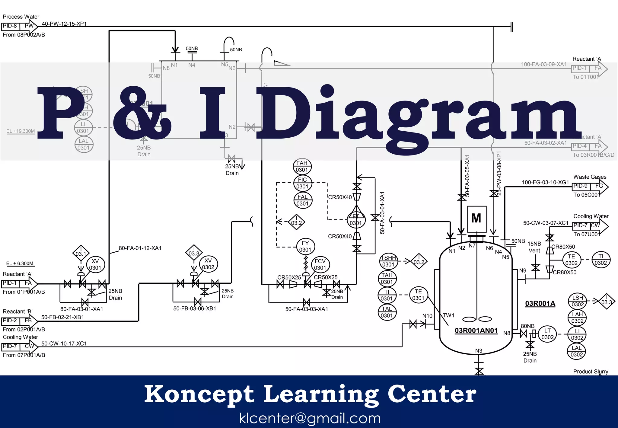
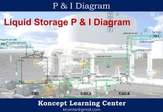

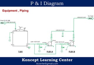
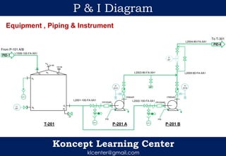
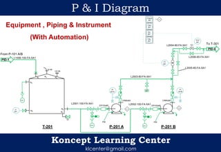
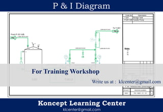

This document appears to be a piping and instrumentation diagram (P&I diagram) for material storage and transfer. It shows a storage tank (T-201), two transfer pumps (P-201A/B), associated piping, and instrumentation. Liquid is transferred from the storage tank to another location (T-301) via the pumps and piping. The diagram labels piping sizes and materials, and instrumentation includes flow transmitters, control valves and indicators.