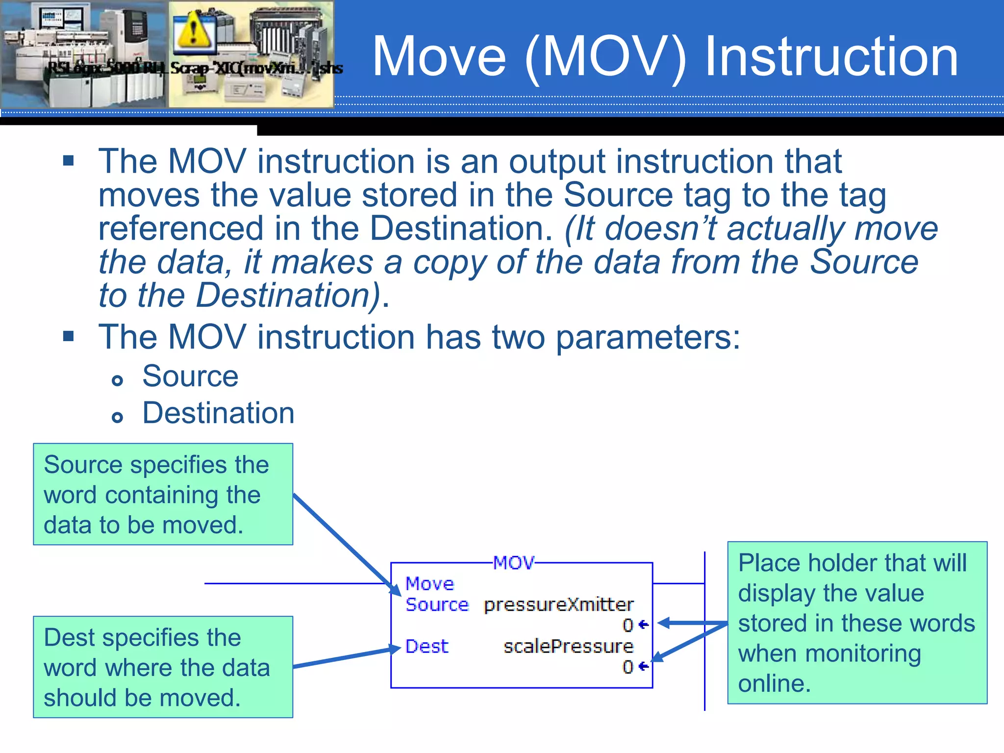
Chapter 06 – Arithmetic and
Move Instructions
Section 6-5-6
Data Manipulation
Instructions
 Data manipulation instructions enable the
programmable controller to manipulate data
stored in memory.
 This extra characteristic gives the PLC/PAC
capabilities that go far beyond the
conventional relay equivalent instructions.
 Data manipulation involves the transfer of
data and operation on data with math
functions, data conversion, data comparison
and logical operations.
Data Manipulation
Instructions
 Words of data memory, in singular form, can be
referred to either as registers, elements or as
words, depending upon the PLC/PAC
manufacturer.
 The terms table, array or file are generally used
when consecutive groups of related data memory
words is referenced. A group of consecutive
elements or words in the ControlLogix controller
are referred to as an array and in Siemens it is
called a table or an array.
 The data contained in files and words will be in the
form of binary bits represented as a series of 1’s
and 0’s.
Data Files, Words and
Bits
This is a pictorial representation of a file
Data Manipulation
Instructions
 Data manipulation instructions allow the
movement, manipulation or storage of
data in either a single or multiple word
groups from one data memory area of the
PLC/PAC to another.
 The use of data manipulation instructions
in applications that require the generation
and manipulation of large quantities of
data generally reduces the complexity and
quantity of the programming required.
Data Transfer
Operations
 Data transfer instructions simply involve the
transfer of the contents of a word from one word or
register to another.
 When new data replaces existing data, the
process is referred to as writing over the existing
data.
 Data transfer instructions can address almost any
location in memory. That location may be the
preset word for a timer or counter or even an
output register that controls the opening and
closing of an IP valve (Current/Pressure Valve) or
a series of outputs from a discrete output module.
Move (MOV) Instruction
 The MOV instruction is an output instruction that
moves the value stored in the Source tag to the tag
referenced in the Destination. (It doesn’t actually move
the data, it makes a copy of the data from the Source
to the Destination).
 The MOV instruction has two parameters:
 Source
 Destination
Place holder that will
display the value
stored in these words
when monitoring
online.
Source specifies the
word containing the
data to be moved.
Dest specifies the
word where the data
should be moved.
Move (MOV) Instruction
 The instruction parameters of a MOV instruction has several
rules:
 The Destination (Dest) must always be a word level tag.
 The Source data can be a word level tag or a program constant.
 MOV instructions can be conditional or unconditional.
Sample Circuit (Why
MOV Data?)
 We are assigned the task of implementing a new circuit that can be
used to control the shut-down of a pump that is being used to pump
sugar syrup or molasses. Because these ingredients have a
different viscosity, the pump needs to run for 10-seconds after the
flow meter states that the correct amount of sugar syrup has been
pumped and for 15-seconds after the flow meter states that the
correct amount of molasses has been pumped.
 Two separate latching NO selector switches are used to select the
product being pumped. One for sugar syrup and one for molasses.
 Nothing should run unless the Start push button is pressed and
everything should stop if the Stop push button is pressed.
 The product being pumped must be selected before the Start push
button will start the process. While a process is running, if the
operator changes the ingredient selector(s), the setting should not
take affect. The Stop push button must be pressed and the process
must be restarted for the new ingredient to take affect.
 Preload time delays into the appropriate tags before downloading
the program.
Sample Circuit
 Field device assignment:
 Start Push Button – Wired to IN9 of the input
module in slot 03. Tag name = startPB
 Stop Push Button – Wired to IN10 of the input
module in slot 03. Tag name = stopPB
 Sugar Syrup Selector – Wired to IN4 of the input
module in slot 03. Tag name = sugarSyrup
 Molasses Selector – Wired to IN6 of the input
module in slot 03. Tag name = molasses
 Pump Motor Starter – Wired to OUT1 of the
output module in slot 06. Tag name = pumpMotor
Simple Circuit
 Build this circuit in class with the class
helping.
Masked Move (MVM)
Instruction
 The Masked Move (MVM) instruction is
slightly different from the MOV instruction in
that a mask word is involved in the MOV.
 The MVM instruction is not an IEC 61131-3
standard instruction.
 The data being moved must pass through a
mask to get to the Dest tag.
 The instruction moves (copies) only the
desired bits from a tag of data type SINT, INT
or DINT from the Source to the Destination
by masking the bits that should not move.
MVM Instruction
 The MVM instruction has three parameters:
 Source
 Mask
 Dest
 The parameters have several rules:
 The Source and Dest must be word level tags.
 The Mask can be a word level tag or a program constant, preferably in
Hexadecimal.
Place holder that will
display the value
stored in these words
when monitoring
online.
Source specifies the
word containing the
data to be moved.
Dest specifies the
word where the data
should be moved.
Mask can be a
hexadecimal number
or word level tag.
MVM Instruction
 The Mask can be thought of as filter. The
data in the Source word will pass through the
filter (mask) and the value exiting the filter
(mask) will be stored in the Dest word.
 Think of the mask as a plate with the number
of holes that correspond to the data type of
the Source word (32-holes for 32-bits (DINT),
16-holes for 16-bit (INT) and 8-holes for 8-
bits (SINT). Each hole has a butterfly valve. If
the valve is closed, nothing can get through
(a zero). If the valve is open, an object can
drop through the hole (a one).
MVM Instruction
The mask shown would be: 1110 0000 1000 0010 or 16#E082
Entering a Constant for
the Mask Value
 When entering the mask value as a
constant it can be entered as a binary,
octal or hexadecimal value. It is usually
best to enter a constant as a hexadecimal
number.
 Entering mask values as constants is done
in the following formats:
 Hexadecimal value: 16#FFA37BC8
 Octal value: 8#2273
 Binary value: 2#101000110011100
MVM Instruction
 Mask operation example
MVM Instruction
DINT mask (32-bits)
INT mask (16-bits)
SINT mask (8-bits)

Move mask moves_rev01_fa16

  • 1.
    Chapter 06 –Arithmetic and Move Instructions Section 6-5-6
  • 2.
    Data Manipulation Instructions  Datamanipulation instructions enable the programmable controller to manipulate data stored in memory.  This extra characteristic gives the PLC/PAC capabilities that go far beyond the conventional relay equivalent instructions.  Data manipulation involves the transfer of data and operation on data with math functions, data conversion, data comparison and logical operations.
  • 3.
    Data Manipulation Instructions  Wordsof data memory, in singular form, can be referred to either as registers, elements or as words, depending upon the PLC/PAC manufacturer.  The terms table, array or file are generally used when consecutive groups of related data memory words is referenced. A group of consecutive elements or words in the ControlLogix controller are referred to as an array and in Siemens it is called a table or an array.  The data contained in files and words will be in the form of binary bits represented as a series of 1’s and 0’s.
  • 4.
    Data Files, Wordsand Bits This is a pictorial representation of a file
  • 5.
    Data Manipulation Instructions  Datamanipulation instructions allow the movement, manipulation or storage of data in either a single or multiple word groups from one data memory area of the PLC/PAC to another.  The use of data manipulation instructions in applications that require the generation and manipulation of large quantities of data generally reduces the complexity and quantity of the programming required.
  • 6.
    Data Transfer Operations  Datatransfer instructions simply involve the transfer of the contents of a word from one word or register to another.  When new data replaces existing data, the process is referred to as writing over the existing data.  Data transfer instructions can address almost any location in memory. That location may be the preset word for a timer or counter or even an output register that controls the opening and closing of an IP valve (Current/Pressure Valve) or a series of outputs from a discrete output module.
  • 7.
    Move (MOV) Instruction The MOV instruction is an output instruction that moves the value stored in the Source tag to the tag referenced in the Destination. (It doesn’t actually move the data, it makes a copy of the data from the Source to the Destination).  The MOV instruction has two parameters:  Source  Destination Place holder that will display the value stored in these words when monitoring online. Source specifies the word containing the data to be moved. Dest specifies the word where the data should be moved.
  • 8.
    Move (MOV) Instruction The instruction parameters of a MOV instruction has several rules:  The Destination (Dest) must always be a word level tag.  The Source data can be a word level tag or a program constant.  MOV instructions can be conditional or unconditional.
  • 9.
    Sample Circuit (Why MOVData?)  We are assigned the task of implementing a new circuit that can be used to control the shut-down of a pump that is being used to pump sugar syrup or molasses. Because these ingredients have a different viscosity, the pump needs to run for 10-seconds after the flow meter states that the correct amount of sugar syrup has been pumped and for 15-seconds after the flow meter states that the correct amount of molasses has been pumped.  Two separate latching NO selector switches are used to select the product being pumped. One for sugar syrup and one for molasses.  Nothing should run unless the Start push button is pressed and everything should stop if the Stop push button is pressed.  The product being pumped must be selected before the Start push button will start the process. While a process is running, if the operator changes the ingredient selector(s), the setting should not take affect. The Stop push button must be pressed and the process must be restarted for the new ingredient to take affect.  Preload time delays into the appropriate tags before downloading the program.
  • 10.
    Sample Circuit  Fielddevice assignment:  Start Push Button – Wired to IN9 of the input module in slot 03. Tag name = startPB  Stop Push Button – Wired to IN10 of the input module in slot 03. Tag name = stopPB  Sugar Syrup Selector – Wired to IN4 of the input module in slot 03. Tag name = sugarSyrup  Molasses Selector – Wired to IN6 of the input module in slot 03. Tag name = molasses  Pump Motor Starter – Wired to OUT1 of the output module in slot 06. Tag name = pumpMotor
  • 11.
    Simple Circuit  Buildthis circuit in class with the class helping.
  • 12.
    Masked Move (MVM) Instruction The Masked Move (MVM) instruction is slightly different from the MOV instruction in that a mask word is involved in the MOV.  The MVM instruction is not an IEC 61131-3 standard instruction.  The data being moved must pass through a mask to get to the Dest tag.  The instruction moves (copies) only the desired bits from a tag of data type SINT, INT or DINT from the Source to the Destination by masking the bits that should not move.
  • 13.
    MVM Instruction  TheMVM instruction has three parameters:  Source  Mask  Dest  The parameters have several rules:  The Source and Dest must be word level tags.  The Mask can be a word level tag or a program constant, preferably in Hexadecimal. Place holder that will display the value stored in these words when monitoring online. Source specifies the word containing the data to be moved. Dest specifies the word where the data should be moved. Mask can be a hexadecimal number or word level tag.
  • 14.
    MVM Instruction  TheMask can be thought of as filter. The data in the Source word will pass through the filter (mask) and the value exiting the filter (mask) will be stored in the Dest word.  Think of the mask as a plate with the number of holes that correspond to the data type of the Source word (32-holes for 32-bits (DINT), 16-holes for 16-bit (INT) and 8-holes for 8- bits (SINT). Each hole has a butterfly valve. If the valve is closed, nothing can get through (a zero). If the valve is open, an object can drop through the hole (a one).
  • 15.
    MVM Instruction The maskshown would be: 1110 0000 1000 0010 or 16#E082
  • 16.
    Entering a Constantfor the Mask Value  When entering the mask value as a constant it can be entered as a binary, octal or hexadecimal value. It is usually best to enter a constant as a hexadecimal number.  Entering mask values as constants is done in the following formats:  Hexadecimal value: 16#FFA37BC8  Octal value: 8#2273  Binary value: 2#101000110011100
  • 17.
    MVM Instruction  Maskoperation example
  • 18.
    MVM Instruction DINT mask(32-bits) INT mask (16-bits) SINT mask (8-bits)