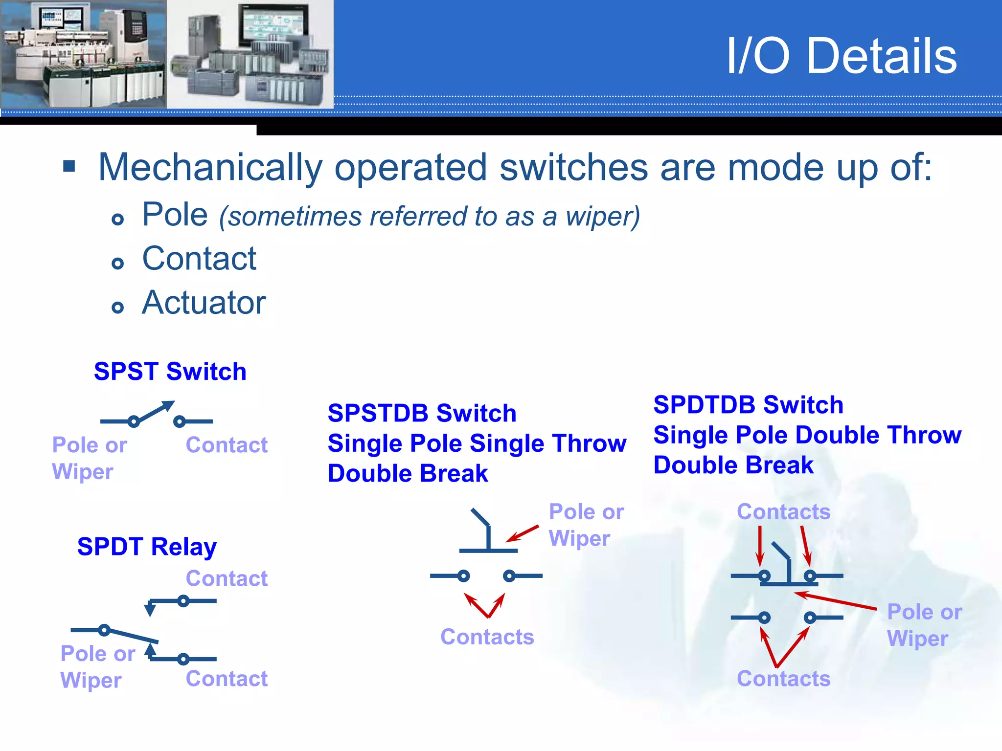
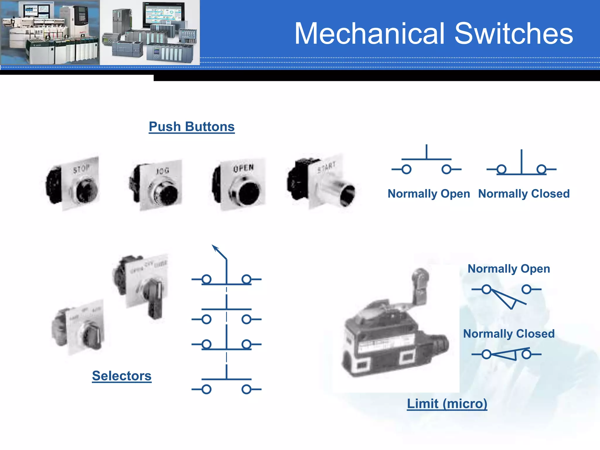
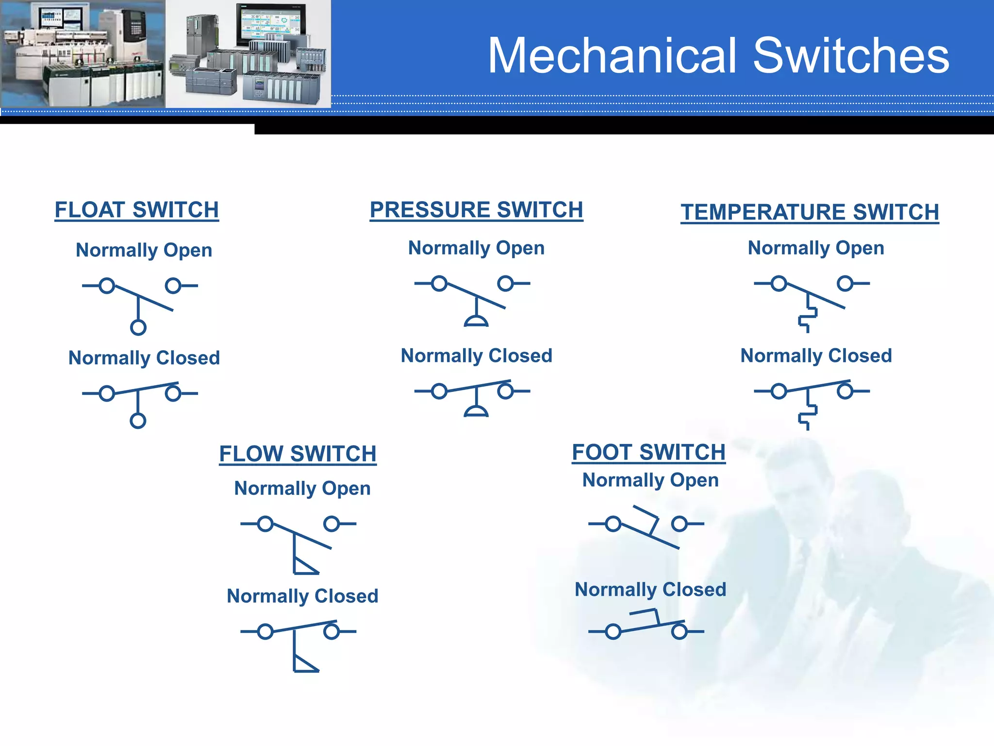
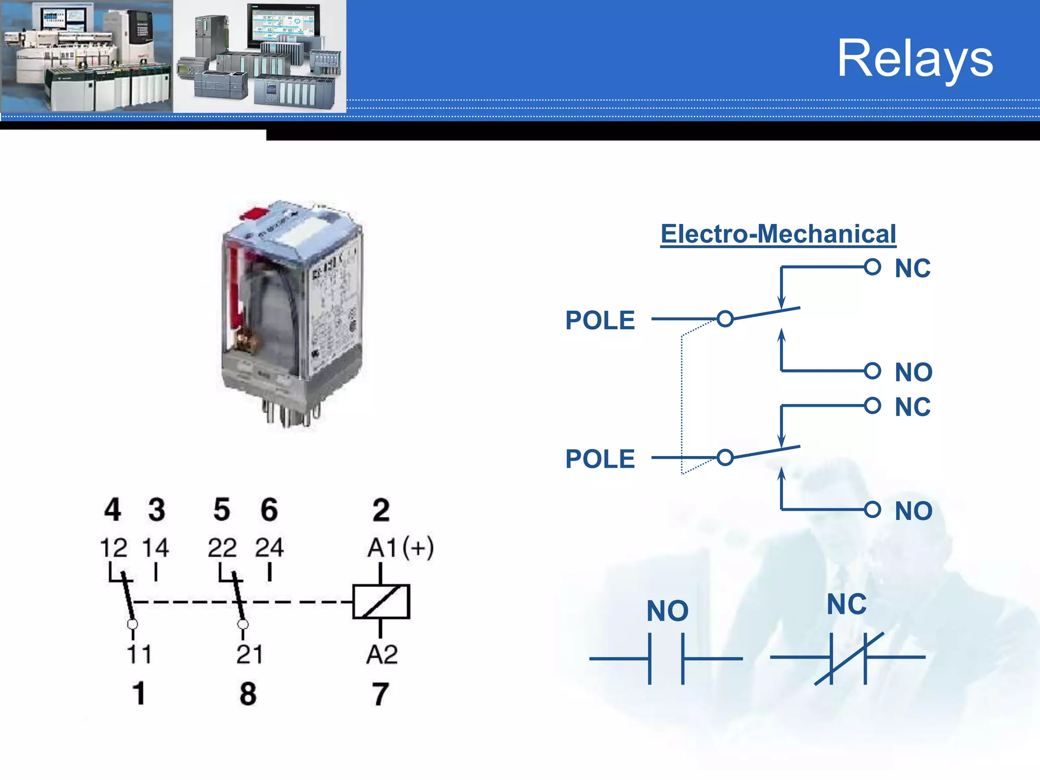
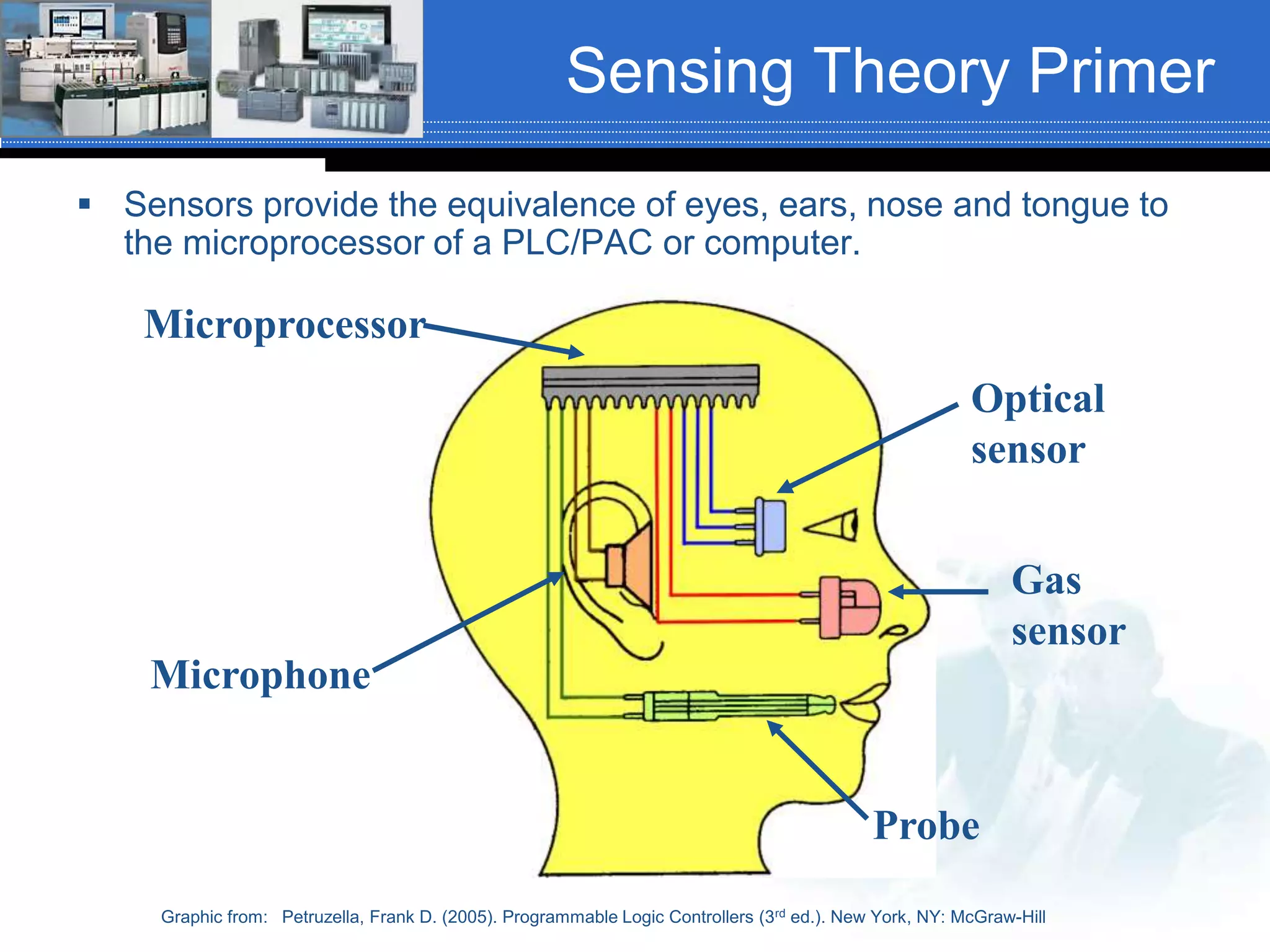
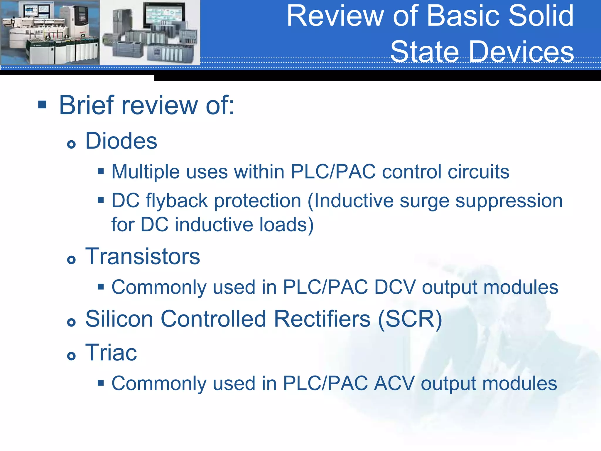
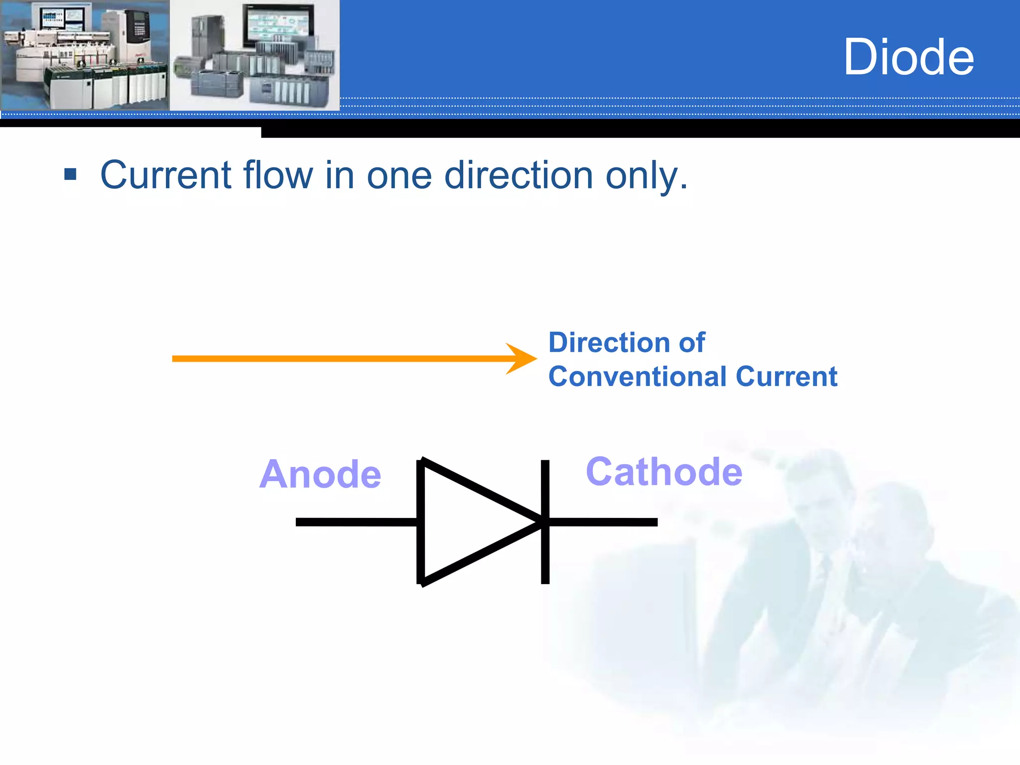
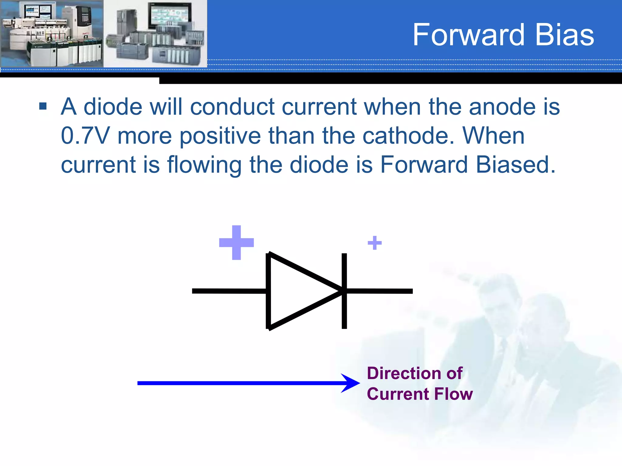
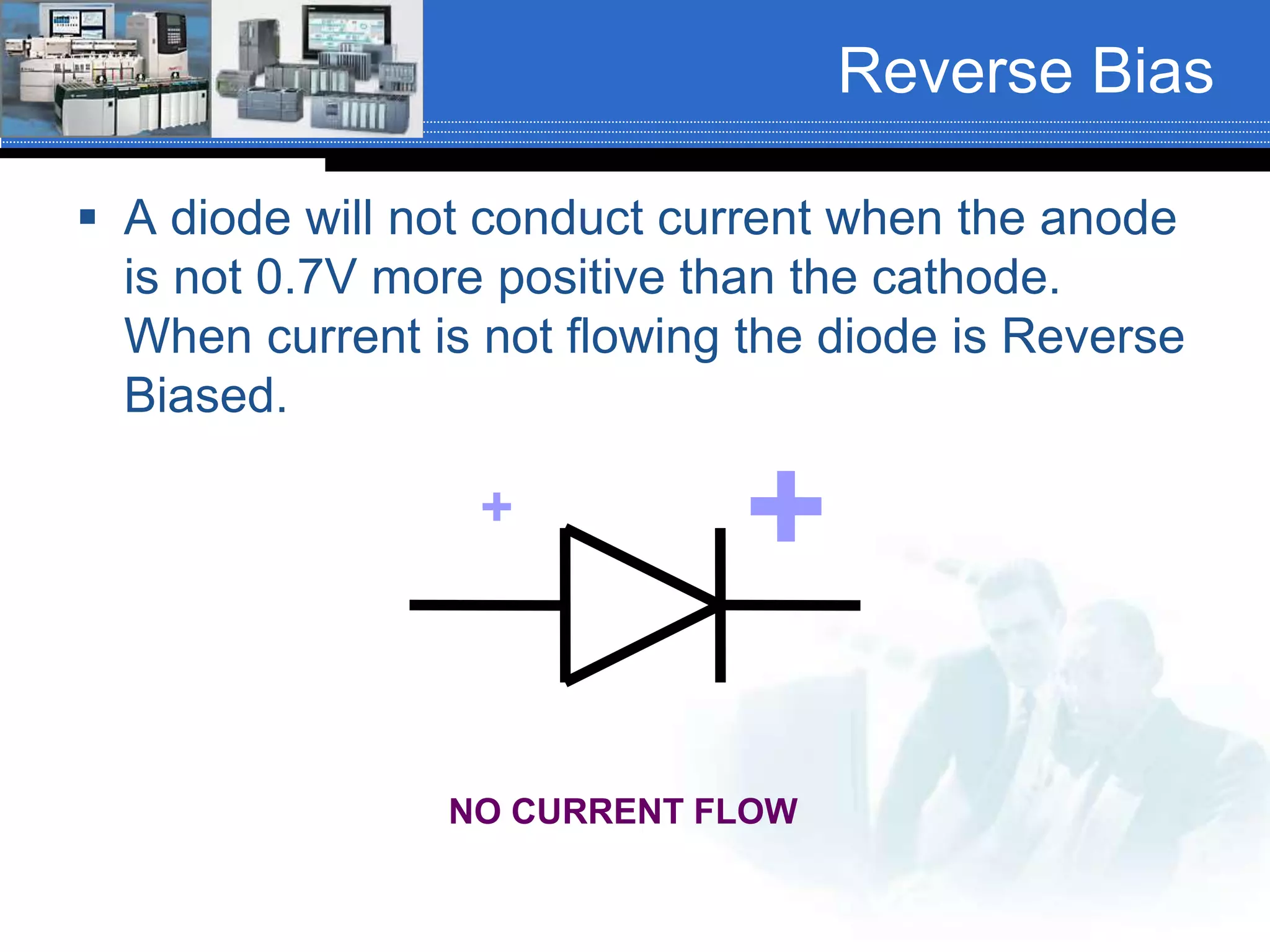
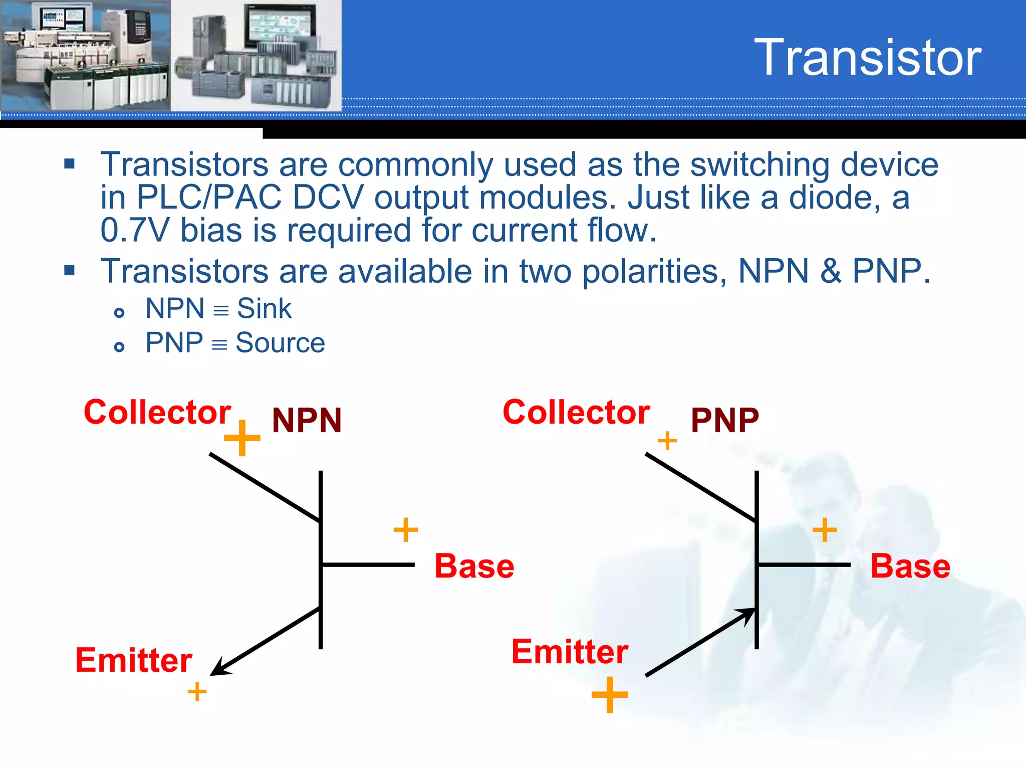
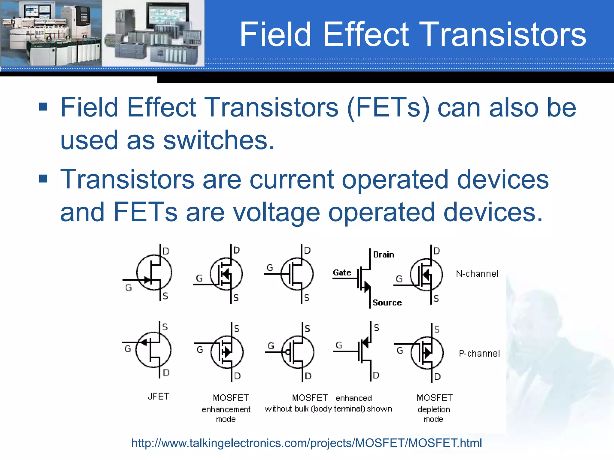
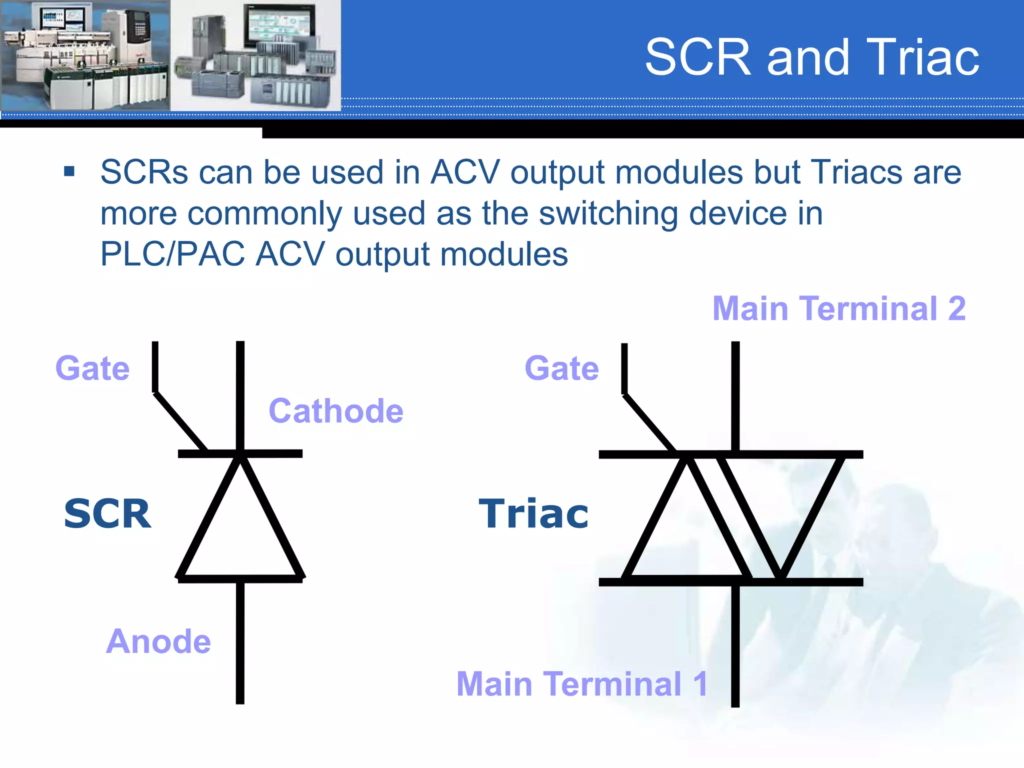
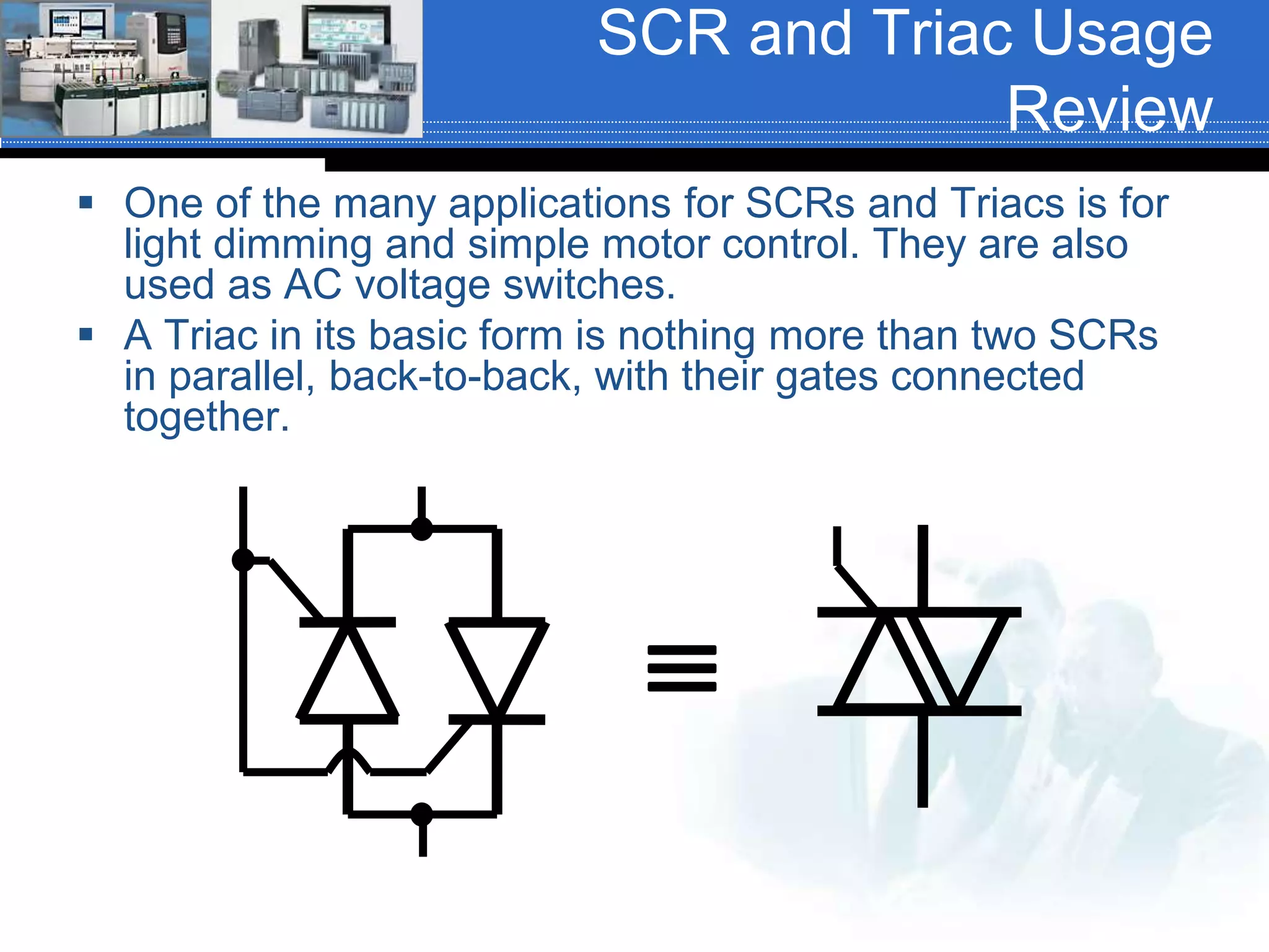
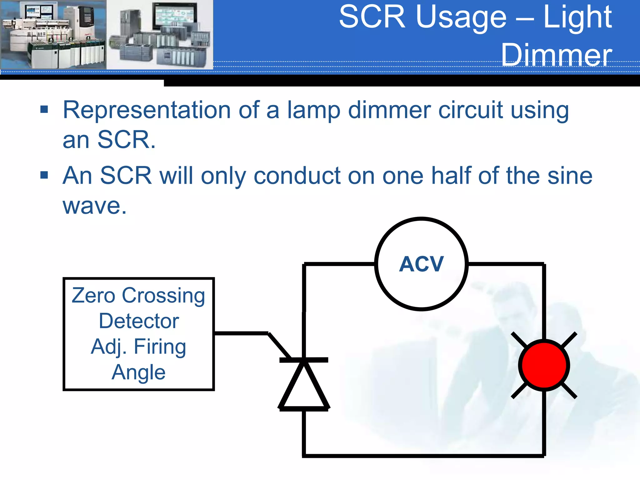
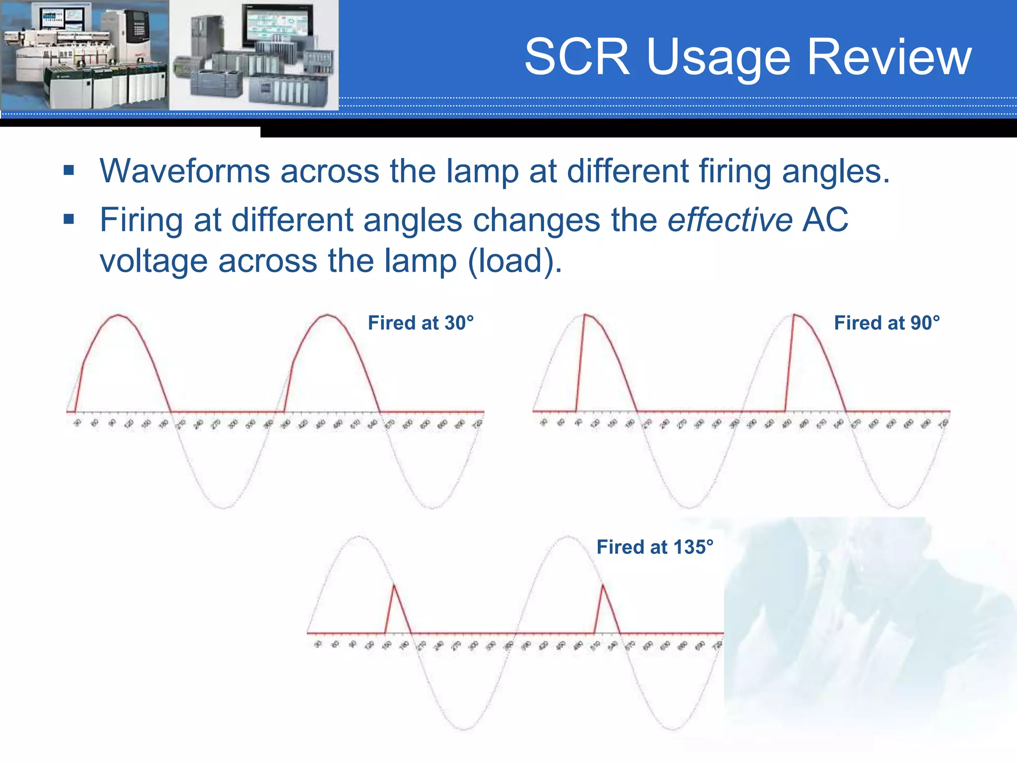
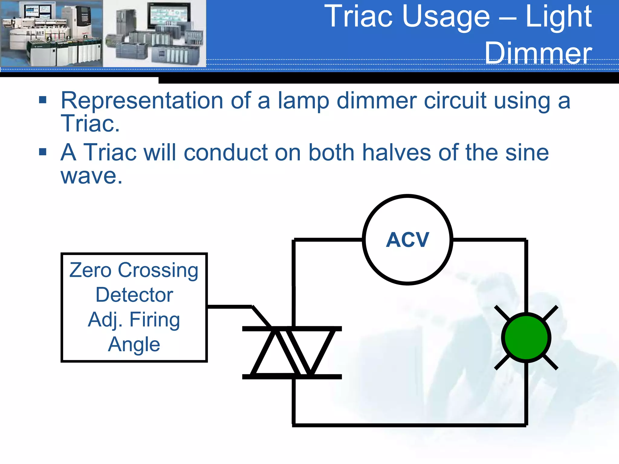
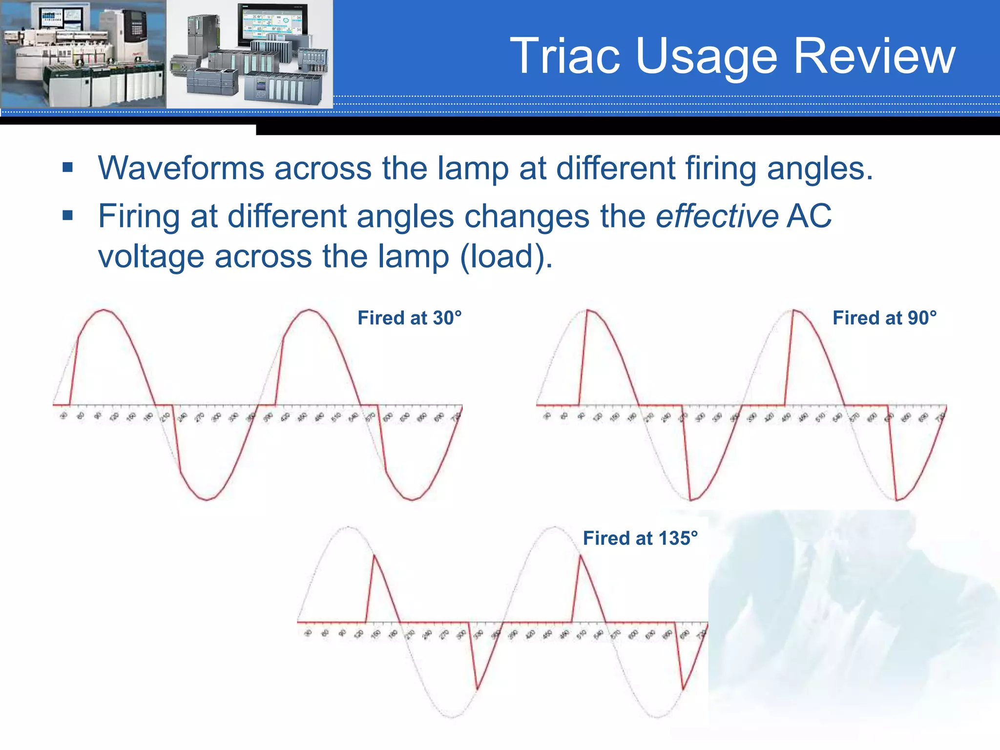
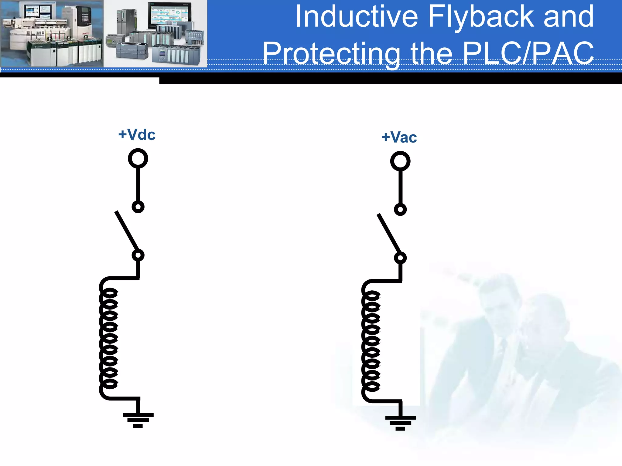
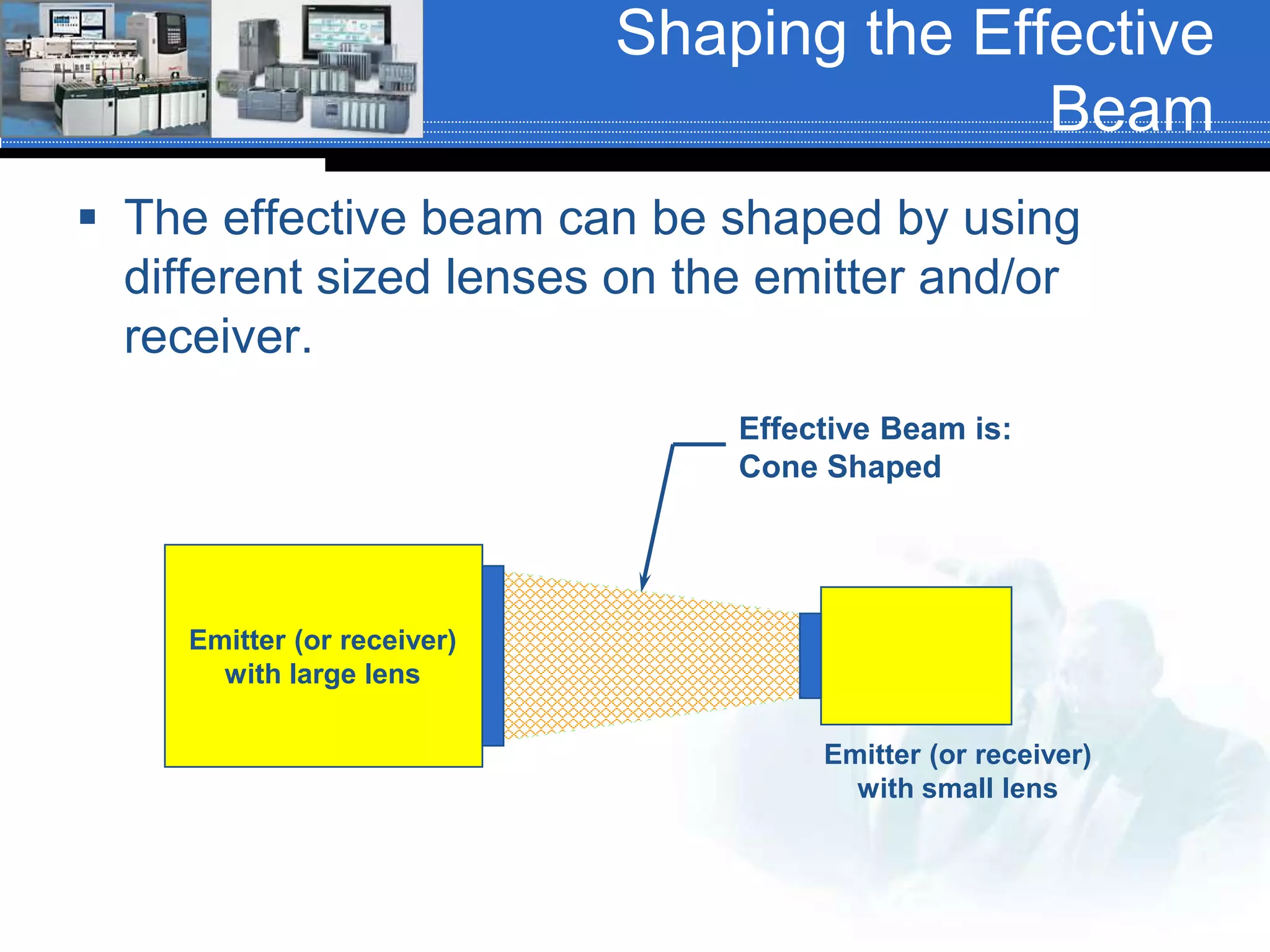
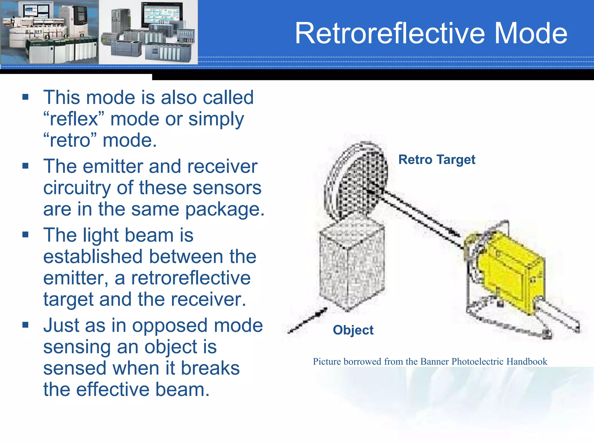
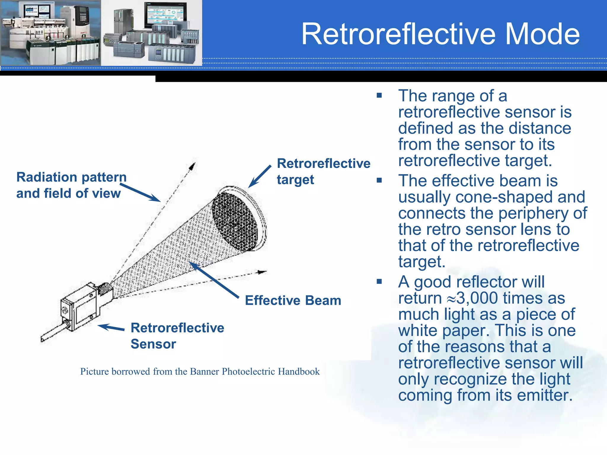
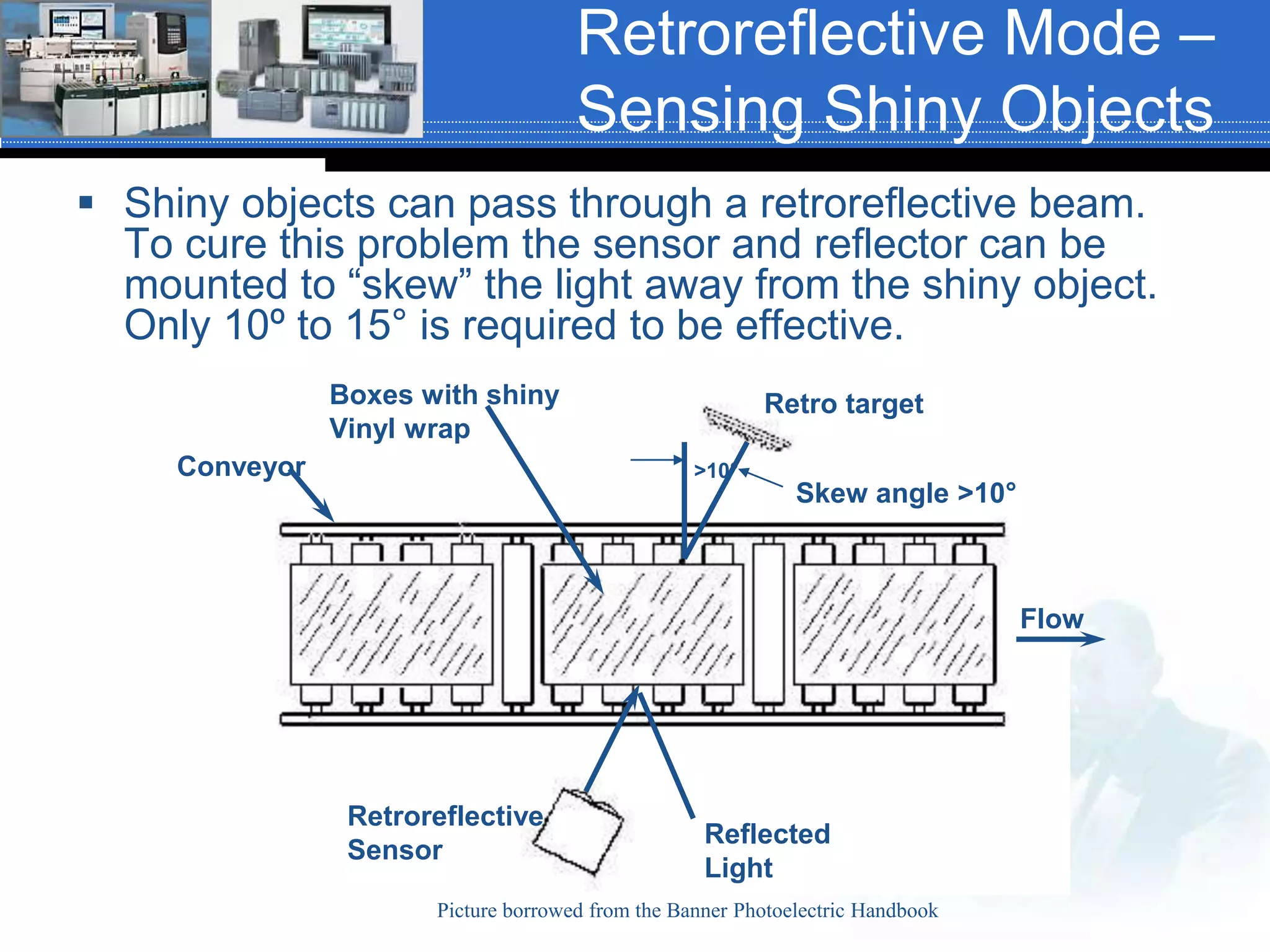
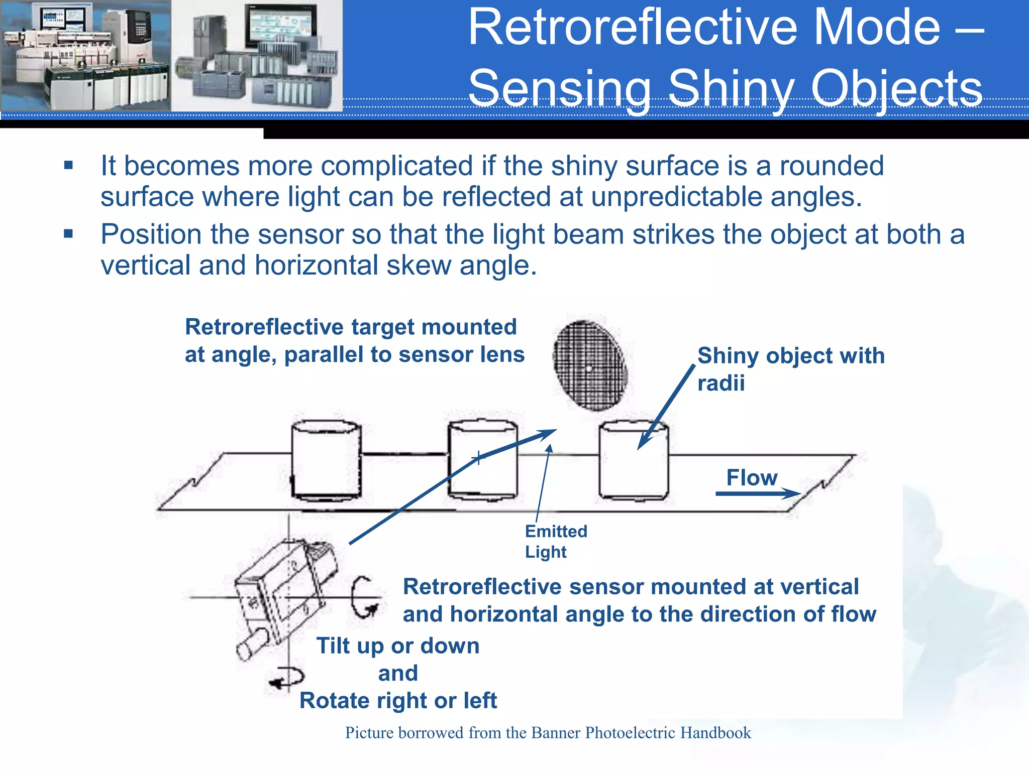
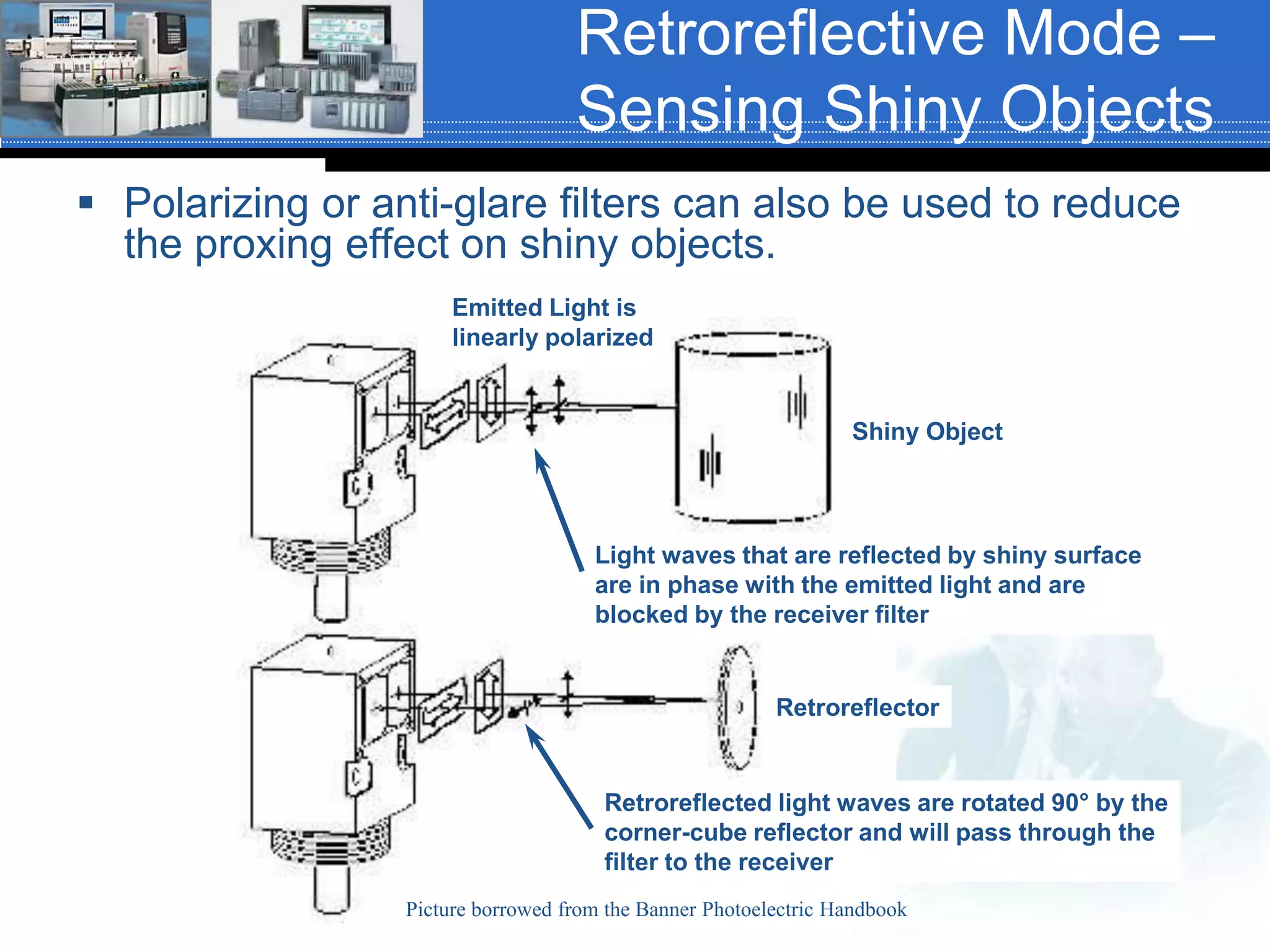
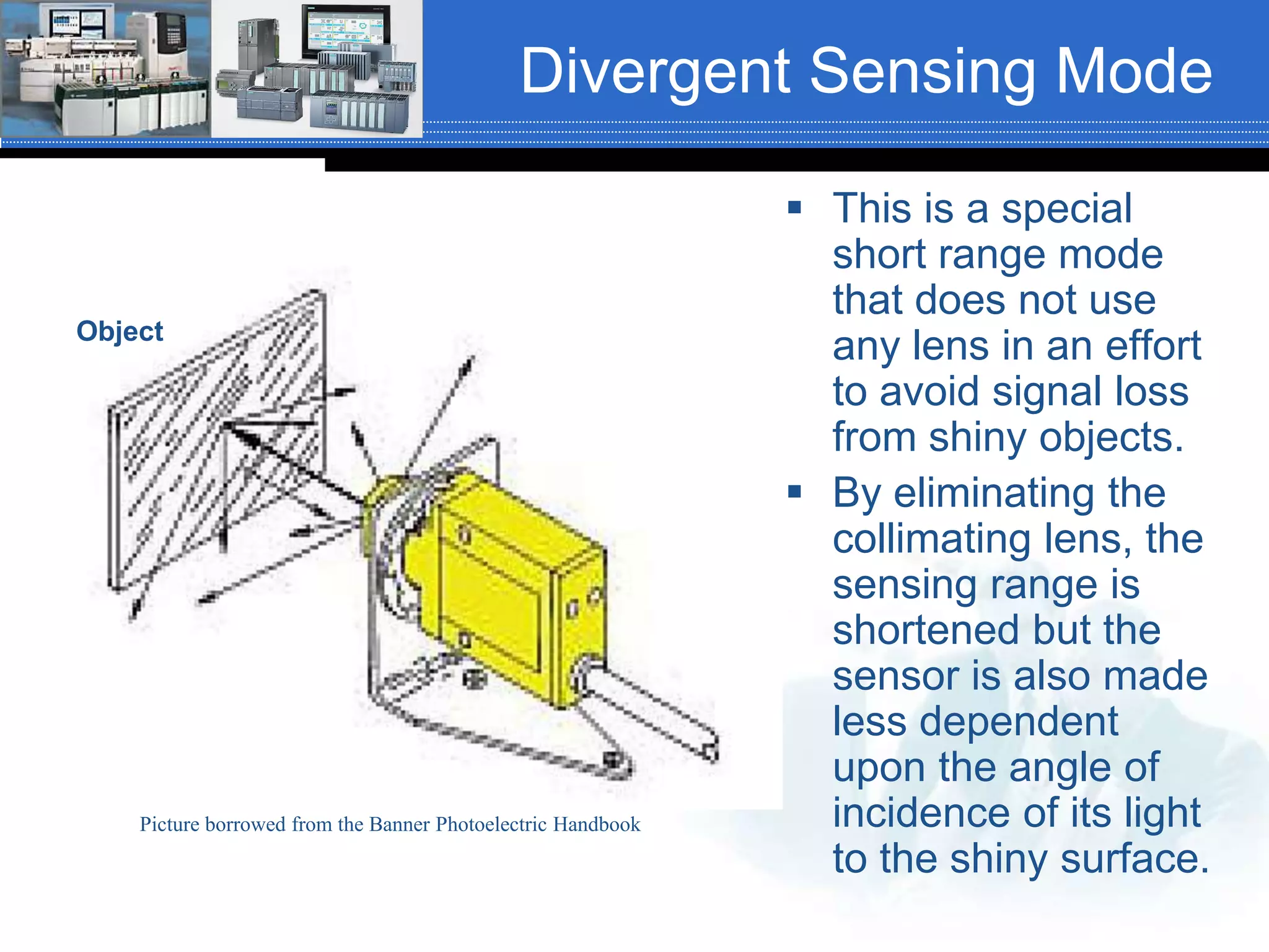
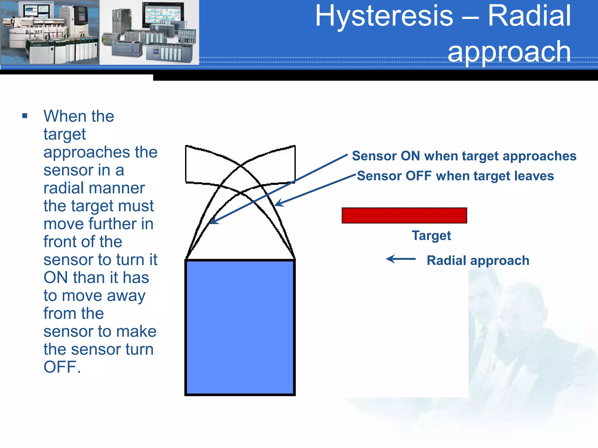
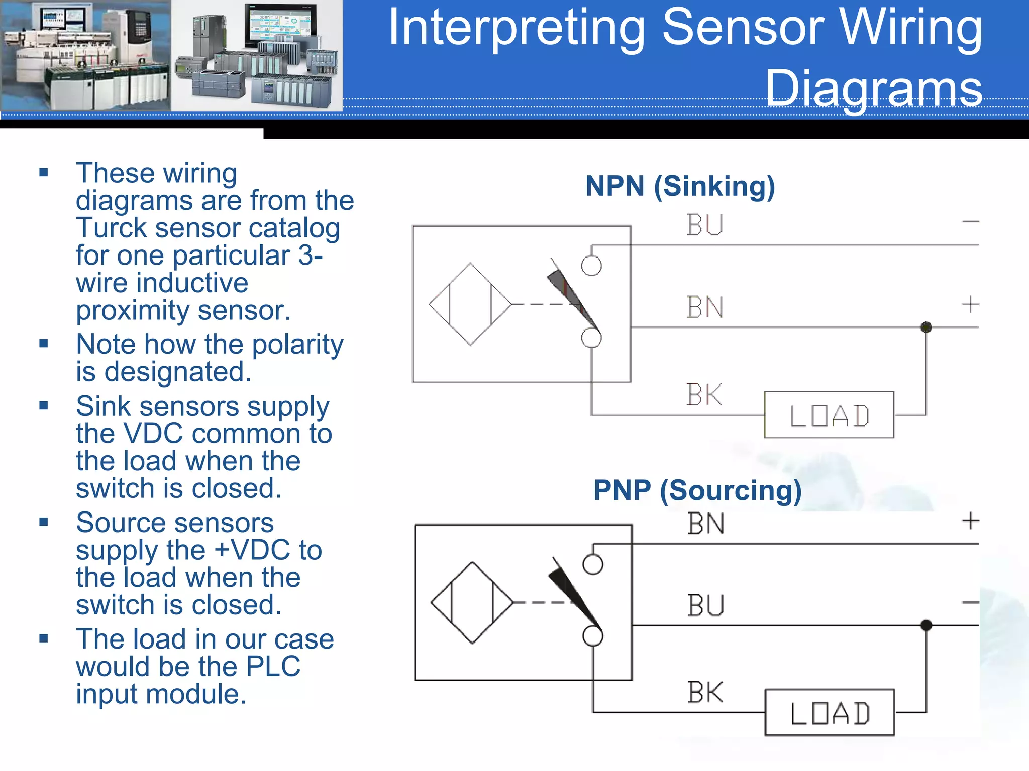
The document provides information on various types of input and output devices used in industrial control systems. It discusses binary, digital and analog I/O devices and provides examples. It also describes different types of mechanical switches, sensors, and solid state devices like diodes, transistors, SCRs and triacs. Additionally, it summarizes different photoelectric sensing techniques such as opposed, retroreflective, and proximity modes as well as concepts like effective beam, ambient light receivers and modulated light sources.
This document discusses analog control systems used with programmable logic controllers (PLCs) and programmable automation controllers (PACs). It describes how analog signals have continuous values between on and off, unlike discrete signals. It then explains that PLCs and PACs use analog input/output modules to interface with field devices that have continuously varying signals, such as temperature sensors, pressure sensors, motors etc. The document provides details on analog signal processing, including analog to digital conversion using ADCs and digital to analog conversion using DACs. It discusses key specifications for analog I/O modules such as resolution, conversion time and settling time.
The document describes the ADC0808 analog to digital converter chip. It has an 8-channel multiplexer that selects which analog input signal to convert to digital. The conversion process takes 64 clock cycles to complete. The chip outputs the digital conversion result on 8 pins and has control signal pins for start, clock, output enable and end of conversion notification. It converts analog voltages to 8-bit digital numbers for use by digital devices like microprocessors.
Microprocessor based Temperature ControllerRevanth Reddy
The document describes the process control system for a wet tannery. It uses temperature and pH sensors to monitor conditions. Signal conditioning circuits prepare the sensor outputs for analog to digital conversion. An 8085 microprocessor reads the digital values and controls loads like heaters via an 8255 interface and solid state relays. The program measures temperature, compares it to a setpoint, and turns the heater on or off accordingly to regulate conditions.
The document discusses analog to digital conversion. It explains that analog signals are continuous while digital signals are discrete in both time and amplitude. It describes how analog signals are converted to digital using sample and hold circuits, quantization, and encoding. The conversion process filters the analog signal, takes samples at regular time intervals, rounds samples to the nearest digital value, and encodes samples into binary format. The document also provides examples of analog to digital converters and discusses considerations like resolution, dynamic range, and signal conditioning.
- Both analog data from the physical world and analog control signals must be converted to digital form to be processed by digital electronics. This involves converting signals from analog to digital and back again from digital to analog.
- There are two main approaches to digital to analog conversion: using a weighted summing amplifier or an R-2R ladder network. The R-2R network is better for higher bit conversions due to greater precision.
- There are three main types of analog to digital converters: digital ramp ADCs, successive approximation ADCs, and flash ADCs. Successive approximation ADCs are faster than digital ramp ADCs but slower than flash ADCs, which are the fastest but require the most circuitry.
This project describes an electronic quiz table that can be used for quiz competitions. The circuit is based on a microprocessor and allows up to five players to participate simultaneously. Each player has a button, and the microprocessor continuously monitors the buttons to determine which player pressed their button. It will light the corresponding LED and display a number on the seven segment display. The microprocessor is reset after each round to prepare for the next round.
The document describes an algorithm for synthesizing a system-level bus from a set of communication channels. The algorithm determines the optimal bus width to balance performance and interconnect cost. It computes the bus rate based on width and delay, and channel rates based on data access patterns and transfer sizes. The bus rate must be greater than or equal to the peak rates of the channels to avoid bottlenecks. The algorithm relates the bus and channel rates to efficiently implement the channels with a single bus.
Analog to digital converter is one of the most important feature of micro controller. here i am explaining about basic of ADC, working and how exactly controller do it. Here i also explaining registers of ADC and attached a sample code.
This document provides information about analog to digital conversion and digital to analog conversion. It discusses different types of converters including flash ADCs, successive approximation ADCs, dual slope ADCs, R-2R ladder DACs, and weighted resistor DACs. It also covers analog and digital signals, the conversion processes, and applications of ADCs and DACs in areas like data acquisition and fiber optic communication.
ANALOG TO DIGITALCONVERTOR FOR BLOOD-GLUCOSE MONITORING csijjournal
This paper presents the design of a low-power CMOS current-frequency (I–F) Analog–Digital Converter. The ADC is designed for implantable blood-glucose monitoring. This current frequency ADC uses nArange of input currents to set and compare voltage oscillations against a self-produced reference to resolve 0–32nA with an accuracy of 5-bits at a 225MHz sampling rate. The comparator used is a dynamic latch comparator and the output is fetched from a 5-bit counter. This is designed in 180nm CMOS technology with a supply of 1.8V, it operating voltage taken here is 0.0- 1.8V with power consumption of 12.3nW using Cadence tools.
The document discusses interfacing analog to digital converters (ADCs), digital to analog converters (DACs), and sensors with PIC18F microcontrollers. It describes the basics of AD conversion including transducers. It then discusses characteristics, registers, and programming of the PIC18F ADC. It also covers DAC concepts and interfacing a DAC0888. Finally, it discusses temperature sensors and interfacing LM34 and LM35 sensors to measure temperature.
The document discusses data acquisition, conversion, and distribution systems in digital control systems. It describes how physical variables are converted to electrical signals via transducers, then amplified and filtered before being multiplexed and converted to digital signals using analog-to-digital converters (ADCs). It provides examples of calculating quantization levels and ADC outputs. Counter-type and successive-approximation ADCs are discussed as common conversion methods.
A microprocessor-compatible quadrature decoder/counter is used to interface an optical shaft encoder (OSE) to a microprocessor's system bus. Quadrature decoder/counter find application in digital data input subsystems and digital closed loop motion control systems.
This document discusses digital-to-analog converters (DACs). It defines a DAC as a circuit that produces an analog output proportional to a digital input and reference voltage. The document describes two main DAC types - multiplying DACs which use an external reference, and non-multiplying DACs which use an internal reference. It also covers DAC circuit types, principles of operation, specifications, errors, and applications of DACs.
This document provides an overview of digital to analog converters (DACs). It begins with an introduction to analog, discrete, and digital signals. It then discusses the basic specifications of DACs including resolution, speed, linearity, settling time, reference voltages, and errors. The document outlines the main types of DACs - weighted resistor DACs, R-2R ladder DACs, switched current source DACs. It also discusses applications such as digital audio and discusses errors that can occur in DACs such as gain error and offset error. In closing, it thanks the reader.
This document discusses different types of analog-to-digital converters (ADCs). It describes flash ADCs, sigma-delta ADCs, digital ramp ADCs, tracking ADCs, and successive approximation ADCs. For each type, it provides a brief explanation of how the circuit works and sometimes includes a diagram. It also lists some common applications of ADCs, such as in transducers, computers, cell phones, microcontrollers, digital signal processing, digital storage, and scientific instruments.
This document describes the design of a 4-bit R-2R ladder digital to analog converter (DAC) using a 90nm CMOS technology process. It first discusses the design of a two-stage CMOS operational amplifier that meets given specifications. The design parameters and SPICE simulation results of the op-amp are then presented. Next, the document explains the principles of an R-2R ladder DAC and provides the specifications for the 4-bit DAC. It shows the SPICE circuit diagram and simulated output waveforms of the DAC. Comparisons are made between the expected and simulated DAC output levels. The document concludes the DAC design is suitable for the 90nm process and future work could enhance the
Wiring a pH and Conductivity Probe to a Zeno3200TAMUK
Short guide explaining how wire a pH and conductivity sensor to a Zeno 3200 data logger. The models mentioned may not be manufactured anymore at this time.
The document describes the design of a 12-bit digital to analog converter (DAC). It includes a binary weighted resistor ladder circuit to convert the digital input to an analog voltage, and an operational amplifier circuit to drive the output load. Simulation results show the DAC can operate at up to 25MHz with good linearity and accuracy. Layout design considerations are discussed to optimize circuit performance and minimize parasitics.
Analog To Digital Conversion (ADC) Programming in LPC2148Omkar Rane
1) The document describes programming the on-chip 10-bit ADC of the LPC2148 microcontroller to implement a simple data acquisition system. It discusses the features of the ADC, the programming interface, control registers, and provides code to initialize the ADC and read conversion results.
2) The code configures the ADC ports and control registers, reads the conversion results when the ADC status indicates a conversion is complete, and prints the voltage levels to the UART.
3) The results show the ADC accurately converts analog voltages from 0-3.1V to their corresponding 10-bit digital values, which are printed to the UART terminal.
This document discusses digital to analog converters (DACs). It explains that a DAC converts digital numbers into analog voltages or currents. The key components of a DAC are its digital input, analog output, and conversion process. Common DAC types include binary weighted resistor DACs and R-2R ladder DACs, which use resistors and switches to implement the conversion. Important DAC specifications are also outlined such as reference voltage, resolution, speed, settling time, and linearity. Common applications of DACs include function generators, digital oscilloscopes, and converting digital video signals to analog formats for display.
Ecd302 unit 03 (part a)(ewb quick reference)Xi Qiu
This document describes the user interface and components available in Electronics Workbench (EWB). It outlines the menus, toolbar, circuit window, and status line. It provides details on the types of sources, basic components, diodes, transistors, integrated circuits, logic gates, digital components, indicators, controls, miscellaneous items, and instruments that can be used in EWB circuits. It also lists some useful analysis features in EWB like DC operating point analysis, AC small-signal analysis, and noise analysis.
This document discusses I/O ports, how to use them, and handling the bouncing problem with switches. It explains that I/O ports allow communication between a microcontroller and the outside world by reading and writing voltage levels on pins. The direction of pins is set by a TRIS register. Switches connected to pins can bounce, so software reads the pin multiple times with a delay to filter out false readings. LEDs are used as simple outputs, requiring current limiting resistors. Sample code is provided to output patterns on one port based on inputs to another, including a function to handle switch bouncing.
KLEA( ENERGY ANALYZER ) & ECRAS ( MULTIMETER ) -KLEMSAN ELECTRIC ELECTRONICdanto .
Who Should Use It?
Users who want to measure and report the energy quality of their establishment.
Users who want to have energy efficiency in their establishment.
Users who want to monitor and report the department energy costs in establishments.
The document provides information about a seminar on embedded systems using the 8051 microcontroller. It discusses the introduction to embedded systems and their components. It then describes the features and architecture of the 8051 microcontroller, including its pins, addressing modes, and timers. Examples of embedded systems are also listed. The document concludes with discussing other integrated circuits like the 8085 microprocessor, 78XX voltage regulators, L293D motor driver, LCD displays, and logic level converters like the MAX232.
This document provides an overview of programmable logic controllers (PLCs) and programmable automation controllers (PACs). It defines PLCs, PACs, and PC-based control systems. The advantages of PLC/PAC control systems are described, including increased reliability, flexibility, lower costs, communications capabilities, faster response time, and easier troubleshooting compared to electromechanical relay-based control. The document discusses PLC/PAC programming languages like relay ladder logic and the modular hardware components of PLC/PAC systems, including the rack/backplane, power supply, processor, I/O modules, and communications connections.
Basics covering analog signals, PLC analog input modules, transducers/transmitters and the wiring of input transducers/transmitters to the PLC analog input module. Single ended and differential wiring are also discussed.
This document discusses specification forms used for instrumentation. It explains that specification forms provide important details about instruments, including signal type, measured fluid, pressure/temperature requirements, and area classification. Standard forms from ANSI/ISA-20-1981 are often modified with additional or omitted fields. Filling out the forms requires process, code, and product knowledge. The document also discusses classified production areas and intrinsic safety.
This document provides information about cascade control systems. It begins with equations for calculating vessel level using differential pressure. It then describes a basic level control loop. It explains a cascade level/flow control loop, where the level controller output sets the setpoint for a flow controller in a secondary loop. A block diagram shows the basic configuration of a cascade control system with a master controller for the primary variable (level) and a slave controller for the secondary variable (flow). It includes a diagram of an example system with tanks, pumps, and a chiller using cascade control to maintain both tank level and chiller flow.
Loop diagrams are schematic representations of instrumentation and control circuits used in process control systems. They show all electrical, pneumatic and physical connections for a loop including signal, power and utility connections. Key elements shown are field devices, control panels, junction boxes and terminal identification. Instrument action (direct or reverse) and energy supplies such as air, power and hydraulic are also identified. Guidelines specify that one loop should be depicted per drawing and that standard symbols are used to represent components and connections.
The document discusses the Copy File (COP) and File Fill (FLL) instructions in Allen-Bradley PLCs and SLC500 controllers. The COP instruction copies data from a source location to a destination location, specifying the source, destination, and length. The FLL instruction fills a destination location with a source value, also specifying the source, destination, and length. Both instructions can copy/fill arrays and structures like timers but require care when filling status-containing structures. An example application uses COP and FLL to copy and configure a thermocouple module's input/output channels.
Module Consolidation: Combining Safety-Critical Automotive Applications with ...Design World
This webinar discusses combining safety-critical automotive applications with non-critical convenience features on a single module or system-on-chip (SoC). It addresses challenges from increasing vehicle complexity and solutions such as consolidating electronic control units (ECUs) and using complex SoCs. Examples of integrating domains like infotainment, driver information, and advanced driver assistance systems are provided. Options for running AUTOSAR communication stacks on external microcontrollers, Linux, or internal processor cores are also examined.
Basic Data Manipulation (MOV and MVM) instructions with a focus on AB ControlLogix. Siemens and AB Creative Components Workbench are mentioned as IEC 61131-3 standard instructions
This document provides information about the G7F-ADHA A/D-D/A module for use with GM7 and MASTER-K80S PLCs. It can convert analog inputs like voltage and current to 12-bit digital values, and convert digital values to analog outputs. Specifications and characteristics of the analog input and output are provided. Examples show how to control an inverter's frequency using 0-10VDC or 4-20mA control signals from the module. Wiring diagrams, programming examples, and attached documents are included to help interface the module with an inverter. Frequently asked questions about the module and interfacing with an inverter are also listed.
This document contains lecture notes on electrical distribution system planning from Dr. A. Arunagiri. It discusses key topics in distribution system planning including factors affecting planning, traditional least cost modeling, demand side planning, the role of computers, and the impact of dispersed storage and generation. It provides examples of different sub-transmission system configurations and distribution system types. The document is divided into numbered pages for a lecture on electrical distribution technology.
1. The document discusses load characteristics that are important for determining power system requirements, planning plant capacity, and selecting generating unit sizes. It defines terms like demand, demand interval, load curves, and load duration curves.
2. Load curves show the load over time, while load duration curves rearrange the loads from highest to lowest. The total load is divided into base, intermediate, and peak loads.
3. The document also defines terms related to load factors like maximum demand, demand factor, average load, load factor, diversity factor, capacity factor, and plant use factor. It provides examples of calculating some of these factors.
Application of Capacitors to Distribution System and Voltage RegulationAmeen San
Application of Capacitors to
Distribution System and Voltage
Regulation
POWER FACTOR IMPROVEMENT,
System Harmonics
Voltage Regulation
Methods of Voltage Control
The document describes a ladder logic program for controlling a traffic light system. The system has two switches: one to run the system according to one of two modes (normal or flashing), and another to select the mode. In normal mode, lights are green for 5 seconds and red for 5 seconds, with 1 second for yellow. In flashing mode, lights flash on and off independently. The ladder logic program uses timers, switches, and coils to control the lights according to the two modes.
This document discusses various input and output devices used with computers. It describes common input devices like the mouse, keyboard, joystick, scanner, and barcode reader which are used to enter data and instructions into a computer. It then explains key output devices such as computer monitors, printers in different types like dot matrix, inkjet and laser, plotters which produce drawings, and microfilm/microfiche which store large amounts of data on film.
Important slideshow for the students of XII vocational bifocal electronics. This slideshow covers 3rd chapter of their syllabus. Very useful for self preparation.
Pre Final Year project/ mini project for Electronics and communication engine...Shirshendu Das
The document describes a project to construct a full wave rectifier circuit that converts 220V AC input into 5V, -5V, and variable 5V DC output. It includes a center tapped transformer, bridge rectifier using 4 diodes, and voltage regulators. Capacitor filters are used to obtain smooth DC waveforms from the pulsating rectified output. The circuit is simulated using NI Multisim software and experimental results are analyzed. Positive 5V output is obtained using an LM7805 regulator, negative 5V output uses an LM7905 regulator, and an LM317 provides adjustable output.
Basics of transducers phys3360AEP3630.pptxTaushifulHoque
This document discusses various types of transducers:
- Transducers convert one form of energy into another and sensors/actuators are input/output transducers. Common sensors include light, temperature, force/pressure, position, speed, sound, and other physical quantity sensors.
- Examples of position sensors discussed include potentiometers, LVDTs, inductive proximity switches, and rotary encoders. Temperature sensors discussed include bimetallic switches, thermistors, PRTs, and thermocouples. Light sensors discussed are photoconductive cells, light level switches, photodiodes, phototransistors, and photovoltaic solar cells.
- Other transducer types briefly discussed
This document provides an overview of electronics concepts including:
- Basic definitions of current, voltage, and resistance according to Ohm's Law.
- Components such as resistors, capacitors, inductors, diodes, transistors, and operational amplifiers.
- Sensor fundamentals and transducers that convert physical quantities to electrical signals.
- Interfacing sensors to the Handy Board and concepts related to digital and analog signals, sampling, quantization, and filtering.
Requirements of a sensor, Principles and Applications of the following types of sensors- Position sensors - Piezo Electric Sensor, LVDT, Resolvers, Optical Encoders, pneumatic Position Sensors, Range Sensors Triangulations Principles, Structured, Lighting Approach, Time of Flight, Range Finders, Laser Range Meters, Touch Sensors ,binary Sensors., Analog Sensors, Wrist Sensors, Compliance Sensors, Slip Sensors, Camera, Frame Grabber, Sensing and Digitizing Image Data- Signal Conversion, Image Storage, Lighting Techniques, Image Processing and Analysis-Data Reduction, Segmentation, Feature Extraction, Object Recognition, Other Algorithms, Applications- Inspection, Identification, Visual Serving and Navigation.
The document discusses diode rectifiers and power supplies. It describes how diodes allow current to flow in only one direction, and how this property is exploited in rectifier circuits to convert alternating current (AC) to direct current (DC). Specifically, it examines the half-wave rectifier circuit, which uses a single diode to rectify the positive half of the AC waveform. The output of the half-wave rectifier is pulsed DC with a large ripple. Power supplies often use rectifier circuits to convert high voltage AC mains electricity to a lower voltage DC for electronic circuits.
The document discusses various types of sensors and transducers, including how they work. It describes infrared (IR) sensors, photodiodes, light dependent resistors (LDRs), thermistors, thermocouples, strain gauges, load cells, potentiometers, encoders, Hall sensors, flex sensors, microphones, and ultrasonic sensors. For each sensor, it provides details on the basic components, working principles, and some common applications.
This document provides an overview of mobile robot platforms and navigation methods. It discusses line follower robots and their basic components like sensors, control logic and drive systems. Specifically, it describes how a simple line follower robot can be built using an LED and LDR pair as sensors, interfaced with an NPN transistor for control logic and a DC motor for locomotion. Design considerations like sensor placement, transistor selection and motor specifications are covered.
Junior cycle science physics in action. By Theresa Lowry-Lehnen. Science Teac...Theresa Lowry-Lehnen
1) Electronic systems are made up of an input sensor, processor, and output device. Logic gates like NOT, AND, and OR are the basics behind any processor.
2) Relays are used to operate devices that require larger currents than logic gates can provide. They are activated by a small current and switch a larger current.
3) Lenses use refraction to bend light rays. Converging lenses make light rays converge to a focal point, while diverging lenses cause light rays to diverge. Lenses are used in cameras, magnifying glasses, and to correct vision.
Lecture note macine & drives (power electronic converter)Faiz Mansur
Power electronics involves controlling and converting electric power using solid-state electronics. There are six main categories of power electronic converters: AC to DC, DC to DC, AC to AC, DC to AC, and static switches. Proper control strategies can reduce voltage and current harmonics generated by power converters. Power electronics have many applications including motor control, power supplies, and HVDC transmission systems. Common power electronic devices include diodes, thyristors, transistors, and newer devices like IGBTs.
A diode is a two-terminal electronic component that allows current to flow in only one direction. It is used to convert alternating current to direct current through a process called rectification. Diodes come in various types including laser diodes, light emitting diodes, Zener diodes, and silicon diodes. Rectification uses diodes to convert AC to DC through either half-wave or full-wave rectification circuits. Zener diodes are used in the reverse bias mode as voltage regulators. Photodiodes generate current or voltage when illuminated by light and are used in applications like machine vision, range finding, and medical diagnostics.
The document discusses various types of sensors and transducers used to measure physical properties such as position, temperature, force, and pressure. It describes common sensors like resistive position transducers, strain gauges, capacitive transducers, inductive transducers, and temperature sensors. It provides details on the basic principles and examples of linear variable differential transformers (LVDTs), resistance temperature detectors (RTDs), thermocouples, and thermistors.
A basic robotics workshop conducted for juniors at BIT Mesra in 2007. The presentation gives an overview of hobby robotics and necessary know how to get started building a robot.
This document describes the design and development of a light intensity meter circuit. The circuit uses a light dependent resistor, voltage divider network, operational amplifiers, analog to digital conversion, and a priority encoder to measure light levels. The output is displayed on a 7-segment display. Key components include an LM324 op-amp, LDR light sensor, 74LS147 priority encoder, and 74LS48 BCD to 7-segment decoder. The circuit aims to provide an inexpensive and accurate way to measure light intensity with a range of 0-2000 lux.
Junior cycle science physics in action. By Theresa Lowry-Lehnen. Science Teac...Theresa Lowry-Lehnen
This document provides information about electronic systems and components. It discusses the three main parts of electronic systems: input sensors, processors, and output devices. It also describes logic gates and their symbols and functions. Diagrams show how to draw circuits using common electronic components like resistors, capacitors, transistors, and relays. Applications of concepts like potential dividers and time delay circuits are explained. The document also covers lenses, ray diagrams, and uses of converging and diverging lenses in applications like cameras, magnifying glasses, and correcting vision.
Week1&2 comm., for engineering techniciansTriza Kamel
This document provides guidance for engineering technicians on interpreting engineering drawings for electronic, electrical, and communication circuits. It begins with an overview of the steps to interpret engineering information, which are to identify components, understand their purpose, and determine the overall circuit purpose. It then details the standard symbols and functions of common circuit components for electronic circuits like wires, power supplies, switches and resistors. The same is done for electrical circuits covering logic gates. Finally, communication circuit components are explained including routers, switches, hubs and network diagrams. Activities are included to have technicians interpret sample circuit diagrams.
This document describes an automatic street light circuit that uses a light dependent resistor (LDR) to sense light levels and control a relay that switches the street light on and off. When it is light outside, the resistance of the LDR is low, which keeps a transistor on and prevents the relay from activating. At night, when light levels drop, the LDR's resistance increases, which allows the transistor to turn off and energizes the relay to power the street light. The circuit uses additional components like a voltage regulator, fuse, resistors and transistors to regulate power and control the switching of the relay based on the LDR's light sensing.
Full Wave Bridge Rectifier simulation (with/without filter capacitor)Jaspreet Singh
1) The document describes a full wave bridge rectifier circuit with and without a filter capacitor.
2) It explains how the circuit works by using 4 diodes to convert an AC input voltage into a DC output voltage that only contains the positive half of the sinusoidal wave.
3) The summary compares the results with and without a filter capacitor, noting that the capacitor reduces the ripple in the output when used.
A linear function is an equation that graphs as a straight line, with the general form of y = mx + b, where m is the slope and b is the y-intercept. A linear equation can be offset by changing the b term, which shifts the line up or down but does not change its slope. The slope of the line can be changed by multiplying the x term by a different value for m. Graphing linear equations with different slopes and offsets demonstrates how varying the terms affects the resulting line.
Comparison instructions, AB, Siemens and AB CCWJohn Todora
Presentation on the operation of the AB ControlLogix comparison instructions. Included is the basics of the Siemens S7-1200 comparison instructions and the AB Creative Components Workbench (CCW) comparison instdructions.
Subroutines are groups of program code that perform specific tasks and can be called from the main routine or other subroutines. They make programs more manageable by breaking them up into smaller tasks. The JSR instruction calls a subroutine, the SBR marks the start of a subroutine, and the RET returns from a subroutine. Parameters can be passed between routines but are not covered in this course. Subroutines improve readability and maintainability and can be reused in other programs.
Basic arithmetic instructions with a focus on AB ControlLogix. Siemens and AB Creative Components Workbench are mentioned as IEC 61131-3 standard instructions
Presentation on the AB ControlLogix counters; CTU and CTD. Also includes a brief introduction to IEC 61131-3 standard counters using Siemens and AB CCW as examples.
Cascade control involves a control loop within a control loop. It uses a secondary feedback loop to monitor a process variable that affects the primary process variable being controlled. This helps the primary controller respond to disturbances more quickly before they impact the primary process variable. Examples given include using air temperature to control room temperature more quickly, and using feed flow rate to control liquid level in a tank before pressure changes affect the level.
The document discusses timers in programmable logic controllers (PLCs). It covers different timer instructions for Allen-Bradley and Siemens PLCs including TON, TOF, and RTO timers. It describes the parameters, status bits, and functionality of TON and TOF timers. It also provides examples of how timers can be used to implement circuits for oscillation, startup warnings, and sequential startup. The maximum timing period of a PLC timer is also summarized.
Chapter 06 - Instrumentation Control Systems Documentation by Frederick A. and Clifford A. Meier. An ISA Publication. This is Rev. 02. It is my own personal opinion that the A. Meier textbook does a horrible job with the Binary Logic Systems and I have therefore supplemented the chapter with other information.
This document introduces some key terms related to instrumentation and control systems documentation, including instruments, instrumentation, process control, and systems. It discusses the importance of documentation standards from the International Society of Automation (ISA) and explains that piping and instrumentation diagrams (PIDs) are used by various engineering and technical roles to understand equipment, trace flow, conceptualize processes, communicate information, and help control processes. The document also outlines different types of industrial processes and highlights some of the sections contained in instrumentation documentation standards.
The document provides an overview of Piping and Instrumentation Diagrams (P&IDs) including their purpose, components, and standard symbols. It discusses that P&IDs are schematic diagrams that define process equipment and instrumentation using standardized symbols. While there is no single universal standard, the ISA 5.1 standard governs common symbols. P&IDs provide key information to support equipment specification and installation through lists generated from the diagrams. Control loops and instrumentation tags are also standardized.
This document from Northampton Community College provides an overview of control systems basics. It defines key terms like control, controller, open loop and closed loop systems. It explains the main components of a control system including sensors, actuators and feedback. It also discusses different types of controllers, control classifications and factors that can affect control systems like disturbances. The document aims to introduce students to the fundamental concepts and components of industrial control systems.
This document provides an overview of industrial automation systems. It defines automated systems as collections of devices working together to accomplish tasks or produce products. Automated systems examples provided include automobiles, which use sensors and computers to control engine operation and other functions, and home security systems, which sound alarms when doors or windows are opened. The document also describes the basic components of industrial automated systems, including production devices, support equipment, controllers, and feedback sensors. It provides details on robotic systems commonly used for repetitive tasks like moving, positioning, and assembling parts. The three main types of industrial robots are pneumatic, hydraulic, and electric. The document includes links to videos demonstrating incredibly fast robots.
This document provides information about sequencers and the sequencer out (SQO) instruction used in programmable logic controllers (PLCs). It defines sequencers as being used to control repetitive and sequential operations, providing examples like dishwashers and packaging machines. It describes mechanical sequencers using cams and drum switches and how programmed sequencer control via a SQO instruction offers more flexibility. The SQO instruction is described in detail, including its parameters and functionality, how it can replace electromechanical switches, and how data is transferred sequentially from a file to outputs.
The document discusses shift register instructions in Allen-Bradley PLCs and PACs. It describes how shift register instructions allow the contents of a register to move bits left or right through a bit array. Specifically, it outlines the parameters and functionality of bit shift left and bit shift right instructions, including how they shift bits in an array one position per rung transition using status bits in a control file.
This document discusses various addressing modes in PLCs, including direct, indirect, indexed, and indexed indirect addressing. It provides examples of each addressing mode using SLC500 and ControlLogix PLCs. Indirect addressing allows data to be accessed using a reference address rather than a direct address. Indexed addressing uses a base address plus an offset value from an index register to calculate the final address. ControlLogix uses arrays instead of indexed addressing, where arrays can have one, two, or three dimensions to store multiple values of the same data type.
This document provides information about comparison instructions and subroutines in PLC programming. It discusses seven common comparison instructions (EQU, NEQ, LES, LEQ, GRT, GEQ, LIM) and how they compare the values in two parameters. It also discusses the parameters and operation of the LIM instruction. Additionally, it provides an example of how comparison instructions can be combined to achieve a desired output based on a value falling within multiple ranges. Finally, it provides a brief introduction to subroutines, including how they can be used to make programs more manageable by breaking code into reusable tasks.
Exploiting Artificial Intelligence for Empowering Researchers and Faculty, In...Dr. Vinod Kumar Kanvaria
Exploiting Artificial Intelligence for Empowering Researchers and Faculty,
International FDP on Fundamentals of Research in Social Sciences
at Integral University, Lucknow, 06.06.2024
By Dr. Vinod Kumar Kanvaria
How to Fix the Import Error in the Odoo 17Celine George
An import error occurs when a program fails to import a module or library, disrupting its execution. In languages like Python, this issue arises when the specified module cannot be found or accessed, hindering the program's functionality. Resolving import errors is crucial for maintaining smooth software operation and uninterrupted development processes.
LAND USE LAND COVER AND NDVI OF MIRZAPUR DISTRICT, UPRAHUL
This Dissertation explores the particular circumstances of Mirzapur, a region located in the
core of India. Mirzapur, with its varied terrains and abundant biodiversity, offers an optimal
environment for investigating the changes in vegetation cover dynamics. Our study utilizes
advanced technologies such as GIS (Geographic Information Systems) and Remote sensing to
analyze the transformations that have taken place over the course of a decade.
The complex relationship between human activities and the environment has been the focus
of extensive research and worry. As the global community grapples with swift urbanization,
population expansion, and economic progress, the effects on natural ecosystems are becoming
more evident. A crucial element of this impact is the alteration of vegetation cover, which plays a
significant role in maintaining the ecological equilibrium of our planet.Land serves as the foundation for all human activities and provides the necessary materials for
these activities. As the most crucial natural resource, its utilization by humans results in different
'Land uses,' which are determined by both human activities and the physical characteristics of the
land.
The utilization of land is impacted by human needs and environmental factors. In countries
like India, rapid population growth and the emphasis on extensive resource exploitation can lead
to significant land degradation, adversely affecting the region's land cover.
Therefore, human intervention has significantly influenced land use patterns over many
centuries, evolving its structure over time and space. In the present era, these changes have
accelerated due to factors such as agriculture and urbanization. Information regarding land use and
cover is essential for various planning and management tasks related to the Earth's surface,
providing crucial environmental data for scientific, resource management, policy purposes, and
diverse human activities.
Accurate understanding of land use and cover is imperative for the development planning
of any area. Consequently, a wide range of professionals, including earth system scientists, land
and water managers, and urban planners, are interested in obtaining data on land use and cover
changes, conversion trends, and other related patterns. The spatial dimensions of land use and
cover support policymakers and scientists in making well-informed decisions, as alterations in
these patterns indicate shifts in economic and social conditions. Monitoring such changes with the
help of Advanced technologies like Remote Sensing and Geographic Information Systems is
crucial for coordinated efforts across different administrative levels. Advanced technologies like
Remote Sensing and Geographic Information Systems
9
Changes in vegetation cover refer to variations in the distribution, composition, and overall
structure of plant communities across different temporal and spatial scales. These changes can
occur natural.
How to Build a Module in Odoo 17 Using the Scaffold MethodCeline George
Odoo provides an option for creating a module by using a single line command. By using this command the user can make a whole structure of a module. It is very easy for a beginner to make a module. There is no need to make each file manually. This slide will show how to create a module using the scaffold method.
it describes the bony anatomy including the femoral head , acetabulum, labrum . also discusses the capsule , ligaments . muscle that act on the hip joint and the range of motion are outlined. factors affecting hip joint stability and weight transmission through the joint are summarized.
ISO/IEC 27001, ISO/IEC 42001, and GDPR: Best Practices for Implementation and...PECB
Denis is a dynamic and results-driven Chief Information Officer (CIO) with a distinguished career spanning information systems analysis and technical project management. With a proven track record of spearheading the design and delivery of cutting-edge Information Management solutions, he has consistently elevated business operations, streamlined reporting functions, and maximized process efficiency.
Certified as an ISO/IEC 27001: Information Security Management Systems (ISMS) Lead Implementer, Data Protection Officer, and Cyber Risks Analyst, Denis brings a heightened focus on data security, privacy, and cyber resilience to every endeavor.
His expertise extends across a diverse spectrum of reporting, database, and web development applications, underpinned by an exceptional grasp of data storage and virtualization technologies. His proficiency in application testing, database administration, and data cleansing ensures seamless execution of complex projects.
What sets Denis apart is his comprehensive understanding of Business and Systems Analysis technologies, honed through involvement in all phases of the Software Development Lifecycle (SDLC). From meticulous requirements gathering to precise analysis, innovative design, rigorous development, thorough testing, and successful implementation, he has consistently delivered exceptional results.
Throughout his career, he has taken on multifaceted roles, from leading technical project management teams to owning solutions that drive operational excellence. His conscientious and proactive approach is unwavering, whether he is working independently or collaboratively within a team. His ability to connect with colleagues on a personal level underscores his commitment to fostering a harmonious and productive workplace environment.
Date: May 29, 2024
Tags: Information Security, ISO/IEC 27001, ISO/IEC 42001, Artificial Intelligence, GDPR
-------------------------------------------------------------------------------
Find out more about ISO training and certification services
Training: ISO/IEC 27001 Information Security Management System - EN | PECB
ISO/IEC 42001 Artificial Intelligence Management System - EN | PECB
General Data Protection Regulation (GDPR) - Training Courses - EN | PECB
Webinars: https://pecb.com/webinars
Article: https://pecb.com/article
-------------------------------------------------------------------------------
For more information about PECB:
Website: https://pecb.com/
LinkedIn: https://www.linkedin.com/company/pecb/
Facebook: https://www.facebook.com/PECBInternational/
Slideshare: http://www.slideshare.net/PECBCERTIFICATION
2. I/O Devices
I/O can be categorized into three areas or types:
Binary (Discrete) (Unfortunately to add some confusion they are
also referred to as Digital)
This includes all mechanical switches such as: pushbuttons,
selectors, limit (micro), motor starter aux. contacts, relay
contacts, etc.
It also includes all solid state sensors such as: photoelectric,
inductive and capacitive proximity, etc.
Digital
This includes: processed video, charge coupled devices
(CCD) arrays, inductive coil impulse generators, optical code
wheels (encoders), etc.
Analog
This includes: potentiometers, linear variable differential
transformers (LVDT), video correlation, pressure,
temperature, flow, strain, etc.
3. I/O Details
Mechanically operated switches are mode up of:
Pole (sometimes referred to as a wiper)
Contact
Actuator
Pole or
Wiper
Pole or
Wiper
Contact
Contact
Contact
SPST Switch
SPDT Relay
SPSTDB Switch
Single Pole Single Throw
Double Break
Pole or
Wiper
Contacts
SPDTDB Switch
Single Pole Double Throw
Double Break
Pole or
Wiper
Contacts
Contacts
11. Sensing Theory Primer
Sensors provide the equivalence of eyes, ears, nose and tongue to
the microprocessor of a PLC/PAC or computer.
Microprocessor
Optical
sensor
Gas
sensor
Microphone
Probe
Graphic from: Petruzella, Frank D. (2005). Programmable Logic Controllers (3rd ed.). New York, NY: McGraw-Hill
12. Review of Basic Solid
State Devices
Brief review of:
Diodes
Multiple uses within PLC/PAC control circuits
DC flyback protection (Inductive surge suppression
for DC inductive loads)
Transistors
Commonly used in PLC/PAC DCV output modules
Silicon Controlled Rectifiers (SCR)
Triac
Commonly used in PLC/PAC ACV output modules
13. Diode
Current flow in one direction only.
CathodeAnode
Direction of
Conventional Current
14. Forward Bias
A diode will conduct current when the anode is
0.7V more positive than the cathode. When
current is flowing the diode is Forward Biased.
+
Direction of
Current Flow
+
15. Reverse Bias
A diode will not conduct current when the anode
is not 0.7V more positive than the cathode.
When current is not flowing the diode is Reverse
Biased.
NO CURRENT FLOW
++
16. Transistor
Transistors are commonly used as the switching device
in PLC/PAC DCV output modules. Just like a diode, a
0.7V bias is required for current flow.
Transistors are available in two polarities, NPN & PNP.
NPN Sink
PNP Source
NPN PNP
+
+
+
+
+
+
Emitter Emitter
Base Base
Collector Collector
17. Field Effect Transistors
Field Effect Transistors (FETs) can also be
used as switches.
Transistors are current operated devices
and FETs are voltage operated devices.
http://www.talkingelectronics.com/projects/MOSFET/MOSFET.html
18. SCR and Triac
SCRs can be used in ACV output modules but Triacs are
more commonly used as the switching device in
PLC/PAC ACV output modules
Gate
Cathode
Anode
Gate
Main Terminal 1
Main Terminal 2
SCR Triac
19. SCR and Triac Usage
Review
One of the many applications for SCRs and Triacs is for
light dimming and simple motor control. They are also
used as AC voltage switches.
A Triac in its basic form is nothing more than two SCRs
in parallel, back-to-back, with their gates connected
together.
20. SCR Usage – Light
Dimmer
Representation of a lamp dimmer circuit using
an SCR.
An SCR will only conduct on one half of the sine
wave.
ACV
Zero Crossing
Detector
Adj. Firing
Angle
21. SCR Usage Review
Waveforms across the lamp at different firing angles.
Firing at different angles changes the effective AC
voltage across the lamp (load).
Fired at 30° Fired at 90°
Fired at 135°
22. Triac Usage – Light
Dimmer
Representation of a lamp dimmer circuit using a
Triac.
A Triac will conduct on both halves of the sine
wave.
ACV
Zero Crossing
Detector
Adj. Firing
Angle
23. Triac Usage Review
Waveforms across the lamp at different firing angles.
Firing at different angles changes the effective AC
voltage across the lamp (load).
Fired at 30° Fired at 90°
Fired at 135°
24. AC Effective Voltage (FYI)
SCRs and Triacs change the effective voltage seen by a
load.
Power calculations based upon a voltage midway
between one peak and zero are not correct because AC
voltage generally changes sinusoidal from zero to peak,
rather than linearly as in DCV.
The voltage value that gives the correct result is called
the Effective Voltage because it has the same effect on a
power calculation as does a DC voltage of the same
value.
Effective Voltage is equal to the square root of the mean
value of the squares of all the instantaneous values of an
AC voltage. Because of that, Effective Voltage is also
known as the Root Mean Square or RMS Voltage.
25. AC Voltmeters (FYI)
AC voltmeters read the AC voltage in one of three ways:
Average
Root Mean Square (RMS)
True RMS
Average responding voltmeters simply use a diode to rectify the AC
signal being measured and read the equivalent DC voltage. Most
VOMs use this method for ACV measurements. (Not very accurate
on non-sinusoidal waveforms).
RMS voltage is a function of power and an RMS meter uses
electronics to simulate an AC power measurement making the ACV
measurement more accurate.
True RMS voltage is also a function of power but also takes into
consideration the heating characteristics of the ACV. True RMS
voltmeters use a sophisticated µP based calculation that will mimic a
bolometer by calculating the area under the curve. This is the most
accurate of ACV measurements. This measurement will include any
spikes or distortion on the AC signal.
Fairly good source to learn more about measuring AC voltage:
http://www.allaboutcircuits.com/vol_2/chpt_1/3.html
27. Photoelectric Sensing
Photoelectric Sensor
An electrical device that responds to a change in the intensity of
the light falling upon it.
Photocell
A photocell is a device that changes resistance when it is
exposed to light. This change in resistance can then be detected
to trigger a response. The earliest method of photoelectric
sensing used a photocell to sense light change.
Non-modulated
The earliest photo sensors consisted of an incandescent light
bulb and a photocell.
The gain of the non-modulated sensor is limited to the point at
which the receiver recognizes ambient light.
This type of sensor is only powerful if its receiver can be made to
see only the light from its light source (emitter).
What are some advantages and disadvantages to this type of
sensor?
28. Ambient Light Receiver
Ambient light receivers are non-modulated type
photoelectric sensors that are still in frequent
use.
Applications for such devices could be:
Detecting red-hot metal or glass that emit large
amounts of infrared light.
As long as these materials emit more light than the
surrounding light level, ambient light receivers can reliably
detect these materials.
A sensor mounted under an open frame conveyor
that is reading the ambient light in the room.
If a box, carton or some other material passes along the
conveyor and over the sensor, it blocks the ambient light
from the sensor. This change in light is used to detect the
presence of an object on the conveyor.
29. Light Sources (Emitters)
Light Emitting Diode (LED)
A solid state device electrically similar to the diode
except that it emits a small amount of light when it is
forward biased.
RED GREEN AMBER
BLUE INFRARED
30. Light Sensor (Receiver)
Phototransistor
A solid state device similar to a transistor except that
the base connection is made using light. These
devices are widely used as photoelectric receivers.
Phototransistor
31. Picture borrowed from the Banner Photoelectric Handbook
Modulated LED Sensors
LEDs can be turned on-
and-off at frequencies
typically in the kilohertz
(KHz) range. This switching
on-and-off is referred to as
modulating the light.
The receiver can be tuned
to this frequency so that it
only sees the light signals
that pulse at this frequency.
This is what gives the LED
sensor its apparent power.
Picture borrowed from the Banner Photoelectric Handbook
33. Opposed Mode Sensing
Picture borrowed from the Banner Photoelectric Handbook
Receiver
Emitter
The emitter
is a light
source
Object
Often referred to as
“Direct Scanning” or
“Break Beam” mode.
In this mode the
emitter and receiver
are positioned
opposite each other
so that the light from
the emitter is aimed
at the receiver.
An object is detected
when it interrupts the
“effective beam” of
light between the two
sensing components.
34. Effective Beam
Photoelectric sensors will sense a change in
light when the effective beam is completely
blocked.
Effective Beam
Radiation Pattern
Field of View
Emitter Receiver
35. Shaping the Effective
Beam
The effective beam can be shaped by using
different sized lenses on the emitter and/or
receiver.
Effective Beam is:
Cone Shaped
Emitter (or receiver)
with large lens
Emitter (or receiver)
with small lens
36. Shaping the Effective
Beam
Apertures can also be placed on the lenses to shape the
effective beam for sensing small objects that would not
normally be large enough to break the effective beam.
Picture borrowed from the Banner Photoelectric Handbook
37. Retroreflective Mode
This mode is also called
“reflex” mode or simply
“retro” mode.
The emitter and receiver
circuitry of these sensors
are in the same package.
The light beam is
established between the
emitter, a retroreflective
target and the receiver.
Just as in opposed mode
sensing an object is
sensed when it breaks
the effective beam.
Retro Target
Object
Picture borrowed from the Banner Photoelectric Handbook
38. Retroreflective Mode
The range of a
retroreflective sensor is
defined as the distance
from the sensor to its
retroreflective target.
The effective beam is
usually cone-shaped and
connects the periphery of
the retro sensor lens to
that of the retroreflective
target.
A good reflector will
return 3,000 times as
much light as a piece of
white paper. This is one
of the reasons that a
retroreflective sensor will
only recognize the light
coming from its emitter.
Retroreflective
Sensor
Radiation pattern
and field of view
Effective Beam
Retroreflective
target
Picture borrowed from the Banner Photoelectric Handbook
39. Retroreflective Mode –
Sensing Shiny Objects
Shiny objects can pass through a retroreflective beam.
To cure this problem the sensor and reflector can be
mounted to “skew” the light away from the shiny object.
Only 10º to 15° is required to be effective.
Boxes with shiny
Vinyl wrap
Conveyor
Retro target
Skew angle >10°
Reflected
Light
Retroreflective
Sensor
>10°
Flow
Picture borrowed from the Banner Photoelectric Handbook
40. Retroreflective Mode –
Sensing Shiny Objects
It becomes more complicated if the shiny surface is a rounded
surface where light can be reflected at unpredictable angles.
Position the sensor so that the light beam strikes the object at both a
vertical and horizontal skew angle.
Picture borrowed from the Banner Photoelectric Handbook
Retroreflective target mounted
at angle, parallel to sensor lens
Retroreflective sensor mounted at vertical
and horizontal angle to the direction of flow
Shiny object with
radii
Flow
Tilt up or down
and
Rotate right or left
Emitted
Light
41. Retroreflective Mode –
Sensing Shiny Objects
Polarizing or anti-glare filters can also be used to reduce
the proxing effect on shiny objects.
Emitted Light is
linearly polarized
Shiny Object
Retroreflector
Light waves that are reflected by shiny surface
are in phase with the emitted light and are
blocked by the receiver filter
Retroreflected light waves are rotated 90° by the
corner-cube reflector and will pass through the
filter to the receiver
Picture borrowed from the Banner Photoelectric Handbook
42. Proximity Mode Sensing
Proximity mode involves detecting an object that
is directly in front of the sensor by detecting the
sensors own emitted energy reflecting back from
the objects surface.
There are five proxing modes:
Diffused
Divergent
Convergent
Fixed field (background suppression)
Adjustable field
43. Diffused Sensing Mode
This is the most
commonly used
photoelectric sensing
mode.
In this mode, the
emitted light strikes the
surface of the object
being sensed at some
arbitrary angle.
The light is then
diffused from the
surface at many angles.
The receiver uses a
lens, whereby it can be
at some arbitrary angle
and still receive a small
portion of the diffused
light.
Emitted Light
Received Light
Object
Picture borrowed from the Banner Photoelectric Handbook
44. Divergent Sensing Mode
This is a special
short range mode
that does not use
any lens in an effort
to avoid signal loss
from shiny objects.
By eliminating the
collimating lens, the
sensing range is
shortened but the
sensor is also made
less dependent
upon the angle of
incidence of its light
to the shiny surface.
Picture borrowed from the Banner Photoelectric Handbook
Object
45. Convergent Beam Sense
Mode
This mode is very effective for
sensing small objects.
They use a lens system to focus
the emitted light to an exact point
in front of the sensor and also to
focus the receiver to this same
point producing a small, intense,
well-defined sensing area at a
fixed distance from the lens.
Depth of Field
Focal Point
Convergent
Beam
Sensor
Picture borrowed from the Banner Photoelectric Handbook
46. Laser Diode Convergent
Sensor
This type of sensor
produces an extremely
small, concentrated focal
point.
The focal point can be in
the order of 0.25mm (0.01”)
in diameter at a sensing
distance of 100mm (4.0”).
The narrow, sharply-
defined beam of a laser
diode can detect the edge
of a semiconductor wafer
(775m or 0.03 in.) in a
wafer cassette mapping
application. (A
representation is shown
here).
Picture borrowed from the Banner Photoelectric Handbook
47. Fixed-Field (Background
Suppression)
Fixed-field mode has a definite limit to its
sensing range. They ignore objects beyond their
sensing range regardless of the objects surface
reflectivity.
Fixed-field sensors compare the amount of
reflected light seen by two differently-aimed
receivers, R1 and R2. A target is recognized as
long as the amount of light reaching R2 is
greater than or equal to the amount of light
reaching R1.
A depiction of a fixed-field mode sensor is
shown on the next slide.
48. Fixed-Field (Background
Suppression)
Picture borrowed from the Banner Photoelectric Handbook
Lenses
Object A Object B
Emitter
Receiver
Maximum Sensing Distance
Minimum
Sensing
Distance
Fixed
Sensing
Field
Senses when light received by R2 ≥ the light received by R1
49. Adjustable Field Mode
Similar to fixed-field,
adjustable field sensors
can distinguish between
objects that are various
distances from the sensor.
The receiver produces
two currents; I1 and I2.
The ratio of the current
changes as the received
light signal moves along
the length of the receiver
element.
The sensing cutoff
distance is directly related
to the ratio of the two
currents which are
adjustable using either
electronic or mechanical
adjustments.
Picture borrowed from the Banner Photoelectric Handbook
50. Sensor Adjustments
Photoelectric sensors need to be properly aligned with
the target whether it is a reflector or the object being
sensed. The alignment is usually accomplished by
mechanically orienting the sensor and/or the target.
Some sensors have “sensitivity” adjustments to adjust
the “gain” of the sensor. This adjustment is made such
that the sensors output ‘just’ turns on/off when the object
to be sensed is within the sensing range.
Excessive gain is a measurement that may be used to
predict the reliability of any sensing system. It is the
measurement of the sensing energy falling onto the
receiver element of a sensing system over and above
the minimum amount required to just operate the
sensors amplifier.
51. Sensor Output Operating
Modes
Light Operated
The sensor output will energize (turn ON)
when the receiver sees light.
Dark Operated
The sensor output will energize (turn ON)
when the receiver sees an absence of light
(darkness).
52. Sensor Response Time
The response time of a sensor is the maximum
amount of time required for the sensor to
respond to a change in the input signal (sensing
event). It is the time between the leading or
trailing edge of a sensing event and the change
in the sensors output.
Response time can be calculated and will be
different depending upon the type of object
being sensed and how the object is moving
(axial, radial direction or rotary).
The formulas for calculating the response time
can be found in the manufacturers specification
sheets or in the manufacturers product catalog.
53. Training Panel Opposed Mode
Sensors
Make adjustments to the photoelectric sensors
on the PLC/PAC training panel.
Banner Engineering
http://www.bannerengineering.com/en-US/
SM31E & SM31R
http://www.bannerengineering.com/en-US/support/partref/25623
Data Sheet
http://info.bannerengineering.com/xpedio/groups/public/documents/literature/03560.pdf
Installation Guide
http://info.bannerengineering.com/xpedio/groups/public/documents/literature/69943.pdf
54. Training Panel Fiber Optic
Sensors
Use the Internet and look up the specifications and data
sheets for the fiber optic sensor.
There are two parts to this sensor, look up both parts
Sensor body
Power block
Read through the data sheets and attempt making some
of the adjustments. (The sensors on the training panel are fairly “beat-
up” from use, so don’t get frustrated if the adjustments do not work perfectly).
When you are finished, the sensor should be “ON” when
the motor wand is present and “OFF” when it’s not
present and the alarm output should be “ON (N/C)”
unless an alarm condition exists.
When you are finished, make sure all the sensors have
their covers reinstalled and the fiber optic sensor is in
“Light Mode” and the opposed mode sensors are in
“Dark Mode”.
55. Inductive Proximity
Sensors
Inductive proximity sensors are used to sense
metal objects.
The sensing distance is usually specified in
millimeters and varies with the size of the sensor.
The smaller the sensor, the closer the object to be
sensed must get to the sensor. As the sensor gets
larger the object sensing distance becomes further.
Operationally they are solid state devices with no
moving parts. They consist of a:
coil
high-frequency oscillator
detector circuit
solid state output
56. Inductive Proximity
Sensors
Operationally, a high-frequency field is generated in a coil mounted in
the nose of the sensor and directed from the sensing surface of the
sensor.
When a metal object enters the high-frequency field, eddy currents are
induced into the surface of the target object.
These eddy currents cause a lose of energy in the high-frequency
oscillator to occur and the amplitude of the oscillator reduces.
The detector circuit detects the reduction in amplitude of the oscillator
and energizes the output circuitry to turn the sensor ON.
Oscillator Detector Output
Target
57. Inductive Prox. Sensor –
Shielded vs. Non-Shielded
Shielded sensor construction includes a metal band that
surrounds the ferrite core and coil of the sensor. The band
helps to bundle or direct the electro-magnetic field to the
front of the sensor.
Non-shielded sensors do not have this metal band and
therefore can be sensitive to sensing objects on the sides of
the sensor.
Shielded sensors can be safely mounted in metal panels or
metal brackets whereas non-shielded sensors require a
metal free area around the face of the sensor.
Spacing of adjacent or opposing sensors must be taken into
consideration due to the possible interference of the electro-
magnetic fields generated. To avoid this problem always
leave at least 2-sensor diameters, center-to-center, between
adjacent or opposing sensors.
58. Mounting Inductive
Proxs.
When mounting inductive prox.
Sensor side-by-side or face-to-face,
there needs to be at least two
sensor diameters between them so
that the magnetic field emanating
from the sensors do not interfere
with each other causing the
possibility of the sensors being ON
all the time.
59. Inductive Prox. Sensor –
Sensing range
The normal sensing range of the
different sensors is basically a
function of the diameter of the
sensing area or sensing coil. The
shape of the target and the alloy
of the metal will also affect the
actual operating range.
Correction factors need to be
applied to non-ferrous targets
and are nominal values.
The table below lists some of
these correction factors.
Sensing range multipliers Shielded Non-Shielded
Aluminum (foil) approx. 1.00 1.00
Stainless steel (alloy dependent) 0.35 to 0.65 0.50 to 0.90
Brass 0.40 0.55
Aluminum (massive) 0.30 0.55
Copper 0.25 0.45
60. Hysteresis
Hysteresis is the distance between the operating
points of an inductive proximity sensor when the
target is approaching the face of the sensor and
the release point when the target is moving
away from the sensor.
As the target approaches the sensor it must
always get closer to the sensor to make the
sensor turn ON then to make it turn OFF when it
is moving away from the sensor.
The following slide demonstrate the hysteresis.
61. Hysteresis – Axial
approach
When the target
approaches the
sensor in an axial
manner the sensor
will turn ON when
the target reaches
the sensors
prescribed sensing
distance.
When the target is
leaving the sensor
the target must be
moved further away
from the sensor then
the prescribed
sensing distance for
the sensor to turn
OFF.
TargetAxial approach
Switch point when leaving
Sensor turns OFF
Switch point
when approaching
Sensor turns ON
62. Hysteresis – Radial
approach
When the
target
approaches the
sensor in a
radial manner
the target must
move further in
front of the
sensor to turn it
ON than it has
to move away
from the
sensor to make
the sensor turn
OFF.
Target
Radial approach
Sensor ON when target approaches
Sensor OFF when target leaves
63. Capacitive Sensors
Capacitive sensors will sense any object that gets within
their sensing range.
They can sense paper, wood, metal, liquid, powders, etc.
They are one of the few sensors that are approved by
the Food and Drug Administration (FDA) to come into
direct contact with consumable food products.
Oscillator Detector Output
Target
A
C
C
B
B
C
B
A
Front View
64. Capacitive Sensors
The active element is formed by two metallic electrodes positioned much
like an “opened” capacitor.
Electrodes A and B are placed in a feedback loop of a high frequency
oscillator.
When no target is present, the sensors capacitance is low making the
oscillator amplitude small.
When a target approaches the face of the sensor, the capacitance
increases resulting in an increase in amplitude of the oscillator.
This amplitude increase is detected by the detector and output of the sensor
is turned ON or OFF.
Oscillator Detector Output
Target
A
C
C
B
B
C
B
A
Front View
65. Capacitive Sensors
Capacitive sensors have a compensation adjustment.
Electrode C is the compensation electrode.
The adjustment can null the affect of water droplets, humidity, dust,
etc. from affecting the operation of the sensor.
In practice the compensation can literally be adjusted to “see
through” objects to another object. As an example, the sensor could
be adjusted to read the ink in a felt tip pen after the cap has been
placed on the pen. (Actual process at Crayola)
Oscillator Detector Output
Target
A
C
C
B
B
C
B
A
Front View
66. Sensor Connections
Sensors come in many connection
configurations. Always read the manufacturer
wiring specifications before connecting a sensor.
Listed are the three most common
configurations:
4-wire Sink or Source
Some of these sensors can be wired as either sink or source.
Not all 4-wire sensors can be wired in either polarity. Some
4-wire sensors can offer NO and NC operation and/or an
alarm output, etc.
3-wire Sink or Source
These sensors are specified as either sink or source when
they are purchased. The polarity can not be changed.
2-wire Sink or Source
These sensors can be wired as either sink or source and are
becoming very popular because of their simplicity.
67. Sensor Connections
Sensor connections vary not only between
manufacturers, but within the same
manufacturer. Always read the manufacturers
wiring specifications before connecting a sensor
into the circuit.
Wire color coding is sometimes used to identify
the sensor connections. The two wires that are
most in common across manufacturers are the
power connections. Remember…sensors are
solid state devices and therefore require power
to operate.
Brown wire – +VDC usually 24VDC
Blue wire – VDC common
68. Interpreting Sensor Wiring
Diagrams
These wiring
diagrams are from the
Turck sensor catalog
for one particular 3-
wire inductive
proximity sensor.
Note how the polarity
is designated.
Sink sensors supply
the VDC common to
the load when the
switch is closed.
Source sensors
supply the +VDC to
the load when the
switch is closed.
The load in our case
would be the PLC
input module.
NPN (Sinking)
PNP (Sourcing)
69. Interpreting Sensor Wiring
Diagrams
This is a wiring
diagram from
the Turck sensor
catalog for one
particular 2-wire
inductive
proximity
sensor.
Note how the
polarity is
designated.
Two wire
sensors can be
wired as sink or
source.
70. Interpreting Sensor Wiring
Diagrams
These wiring diagrams
are from the Turck
sensor catalog for one
particular 4-wire
inductive proximity
sensor.
Note how the polarity is
designated.
This sensor has one
pole, a normally open
(N.O.) and a normally
closed (N.C.) contact.
(SPDT)
NPN (Sinking)
PNP (Sourcing)
71. Interpreting Sensor Wiring
Diagrams
These wiring
diagrams are from
the Turck sensor
catalog for one
particular 4-wire
inductive proximity
sensor.
Note how the
polarity is
designated.
This sensor have
one pole, a
normally open
(N.O.) and normally
closed (N.C.)
contact. (SPDT)
NPN (Sinking)
PNP (Sourcing)
72. Interpreting Sensor Wiring
Diagrams
This wiring diagram is from the Banner Engineering
manual for a particular 4-wire sensor.
This sensor is Bipolar, meaning that a sink or source
load can be switched depending upon which lead, the
white or black, that is connected to the load.
White – Sink connection
Black – Source connection
73. Interpreting Sensor Wiring
Diagrams
These
diagrams
are of a
Keyence
photo –
electric
sensor.
This is an
example of
why the
manf. data
sheets are
required.
74. I/O MODULES ARE AVAILABLE IN MANY DIFFERENT
CONFIGURATIONS
PLC/PAC Module Wiring
75. I/O Module Wiring
PLC/PAC I/O modules are available in many
different wiring configurations:
The entire module is either sink or source and
uses one I/O power source.
The module is split in two halves where one half
can be sink and the other half can be source or
both halves can be sink or source. When used
split, two different I/O power sources can be
used.
The module is split into more than two halves
where each section can be independent from the
others or can be combined into one section.
76. Single Section Module
This is module is a
single section
module. The
polarity (sink or
source) of a single
section module is
determined by the
manufacturer and
cannot be changed.
All I/O must be
capable of
operating from the
same power
source.
77. Split Module – 2 Sections
Group 0 Group 0
Group 1 Group 1
This module is split
into 2-sections. The
2-sections are the
same polarity,
(source), but each
section can be
powered from a
different power
source.
78. Split Module – 4 Sections
Group 0 Group 0
Group 3
Group 3
Group 1 Group 1
Group 2 Group 2
This module is split
into 4-sections. The
4-sections are the
same polarity,
(sink), but each
section can be
powered from a
different power
source.
79. Split Module – 2 Sections
This module is split
into 2-sections.
Each section can
be wired as either
sink or source and
use different power
sources. Also,
terminals CA and
CB can be jumped
and the entire
module can be
wired as either sink
or source.
80. Class Wiring Exercise
Instructor led wiring exercise
Use Training Panel Prints and discuss the
wiring of the panel.
Equipment
Training panel wiring schematics
Digital Multimeter (DMM)
Editor's Notes
When a switch is wired to the input module of a PLC and the switch bounce becomes bad enough, the PLC could see multiple opens and closures for one activation of the switch.
What the diffierence between conventional current flow and electron?
The old (conventional) current flow says that where there is a surplus of charge ( meaning positive) the current flows towards a deficient point (which means negative). However later discovery found that electrons which are negatively charged constitute this current flow and electrons move towards a positively charged body - not the other way around. This has now become the electron flow - the movement of electrons from surplus point (negative) towards a less neagative (deficient) point. So we can say now that in a complete circuit using for instance a battery, the electron current flows from the Negative side of the battery towards the Positive side via the external load.Read more: http://wiki.answers.com/Q/What_the_diffierence_between_conventional_current_flow_and_electron#ixzz1WVw6WXz3
What the diffierence between conventional current flow and electron? read more:
http://wiki.answers.com/q/what_the_diffierence_between_conventional_current_flow_and_electron#ixzz1wvwbjkt5. (2011). Retrieved from
http://wiki.answers.com/Q/What_the_diffierence_between_conventional_current_flow_and_electron
Advantages:
Simple
Affordable
Will work at long distances
Disadvantages:
Alignment is difficult and needs to be periodically performed.
The photo cell must see the “hot spot” of the light bulb (emitter).
Light bulbs burn out.
Filaments sag with heat and long use changing the position of the “hot spot” therefore changing the alignment.
When changing a burned out bulb, the filament is usually not in the same physical location as the previous bulb and alignment will need to be performed.
Must be shielded from ambient light.
Brewster’s law, relationship for light waves stating that the maximum polarization (vibration in one plane only) of a ray of light may be achieved by letting the ray fall on a surface of a transparent medium in such a way that the refracted ray makes an angle of 90° with the reflected ray. The law is named after a Scottish physicist, Sir David Brewster, who first proposed it in 1811.
The figure shows a ray of ordinary (nonpolarized) light of a given wavelength incident on a reflecting surface of a transparent medium (e.g., water or glass). Waves with the electric field component vibrating in the plane of the surface are indicated by short lines crossing the ray, and those vibrating at right angles to the surface, by dots. The plane of incidence (AON) is the plane that contains the incident ray and the normal (ON, a line perpendicular to the surface) to the plane of the surface such that they intersect at the surface. Most of the waves of the incident ray will be transmitted across the boundary (the surface of the water or glass) as a refracted ray making an angle r with the normal, the rest being reflected. For a specific angle of incidence (p), called the polarizing angle or Brewster’s angle, all reflected waves will vibrate perpendicular to the plane of incidence (i.e., to the surface), and the reflected ray and the refracted ray will be separated by 90°. Brewster’s law also states that the tangent of the angle of polarization, p, for a wavelength of light passing from one substance to another is equal to the ratio of the refractive indices, n1 and n2, of the two contacting mediums: tan p = n2/n1.
Brewster’s law. (2011). In Encyclopædia Britannica. Retrieved from http://www.britannica.com/EBchecked/topic/79080/Brewsters-law
An eddy current is the current is induced in little swirls ("eddies") on a large conductor (picture a sheet of copper). If a large conductive metal plate is moved through a magnetic field which intersects perpendicularly to the sheet, the magnetic field will induce small "rings" of current which will actually create internal magnetic fields opposing the change. This is why a large sheet of metal swung through a strong magnetic field will stop as it starts to move through the field. All of its kinetic energy will cause a major change in the magnetic field as it enters it which will induce rings of current which will oppose the surrounding magnetic field and slow the object down. In effect, the kinetic energy will go into driving small currents inside the metal which will give off that energy as heat as they push through the metal.
If this isn't a satisfying answer, consider a simple wire loop being moved through a magnetic field. If you've learned anything about motors and/or generators, you will have probably learned that a current will be induced in this loop in a similar fashion. Likewise, a wire loop being pushed into a magnetic field will induce a current which will make it difficult to continue pushing. Likewise, it will resist being pulled out as well. An eddy current does the same thing, but instead of being forced in the path of the loop, it is allowed to travel in the "eddy" pattern that nature provides.
To get rid of eddy currents, slits can be cut in metals so that large eddies cannot occur. This is why the metal cores of transformers are often assembled in small laminations with an insulator in between. This prevents AC energy from being lost to eddies generated within the magnetic core (which typically is also conductive because it is a metal like iron).
Now, sometimes eddy currents are a good thing. Mentioned above, eddy currents help turn kinetic energy quickly into other forms of energy. Because of this, braking systems have been created which take advantage of it. Adding a magnetic field around a spinning piece of metal will cause eddy currents in that metal to create magnetic fields which will slow the object spinning down quickly as long as the magnetic is strong enough.
Now, this can be taken one step farther and a circuit can be built which shuffles kinetic energy turned into electrical energy back into a battery. This is what many Hybrid cars do (and Dean Kamen's "Segway" not only when it is stopping but when it is going downhill). Answered by: Ted Pavlic, Electrical Engineering Student
Pavlic, T. (2011). What is an eddy current? . Retrieved from http://www.physlink.com/education/askexperts/ae572.cfm
Example:
Sensor range is 4mm:
for brass, the sensing range for a shielded sensor would be 1.6mm and for an non-shielded sensor it would be 2.2mm.