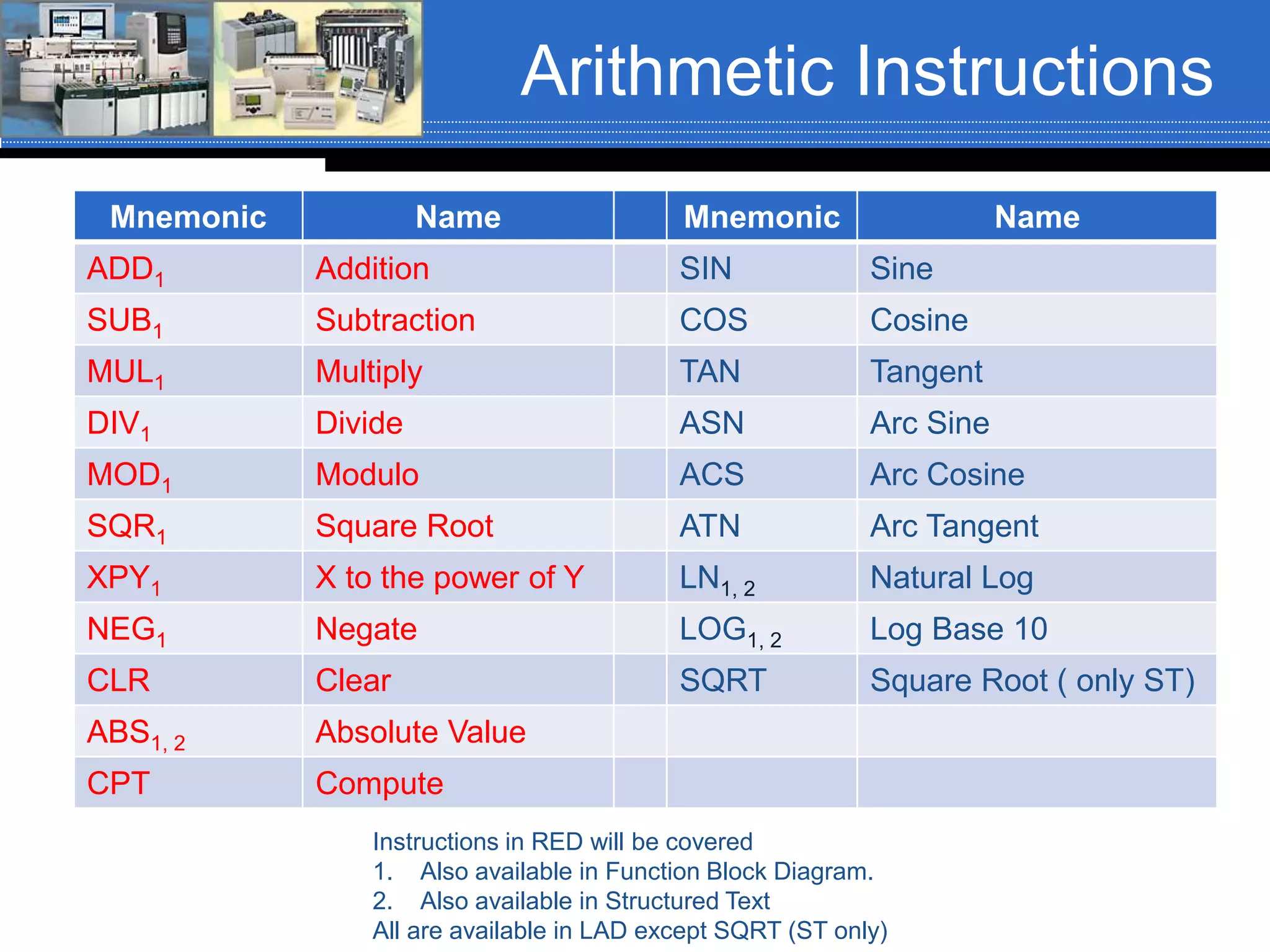
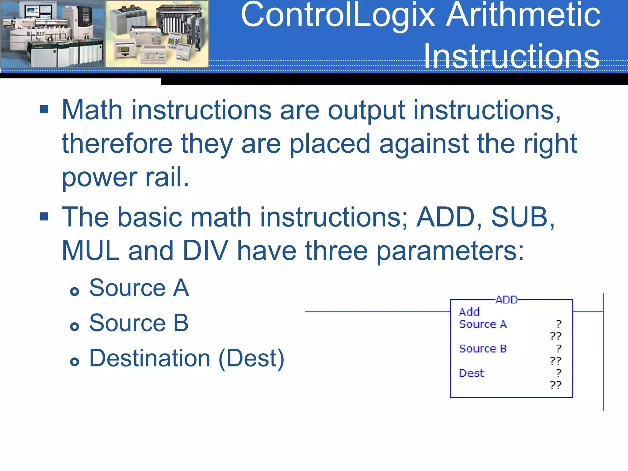
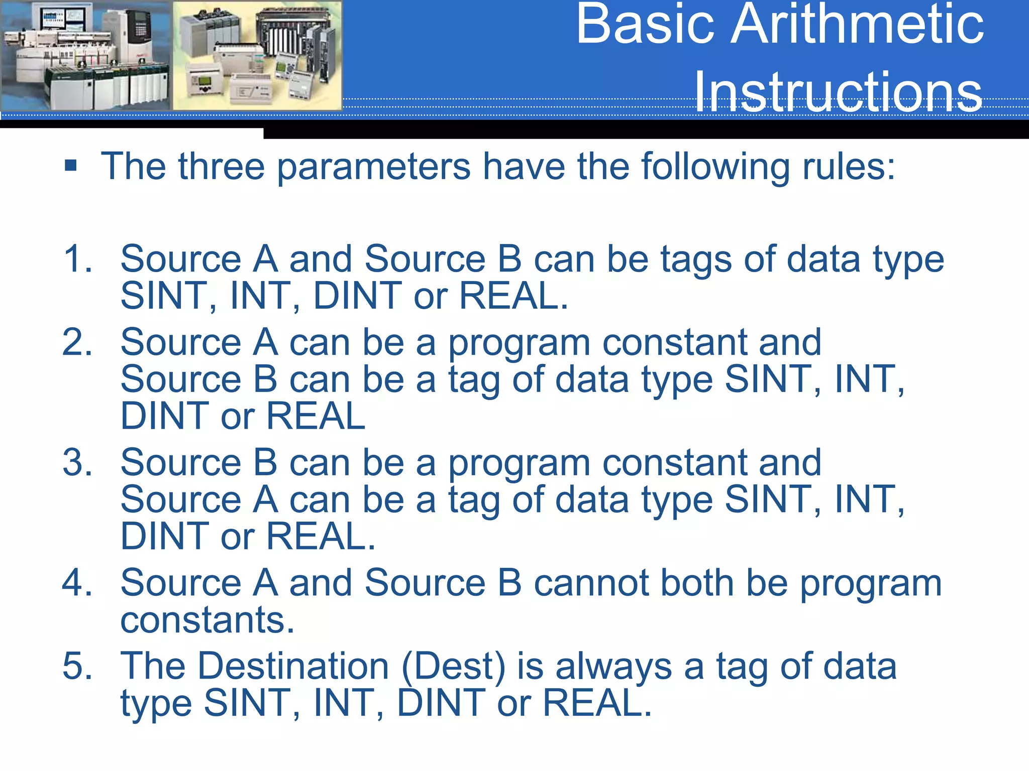
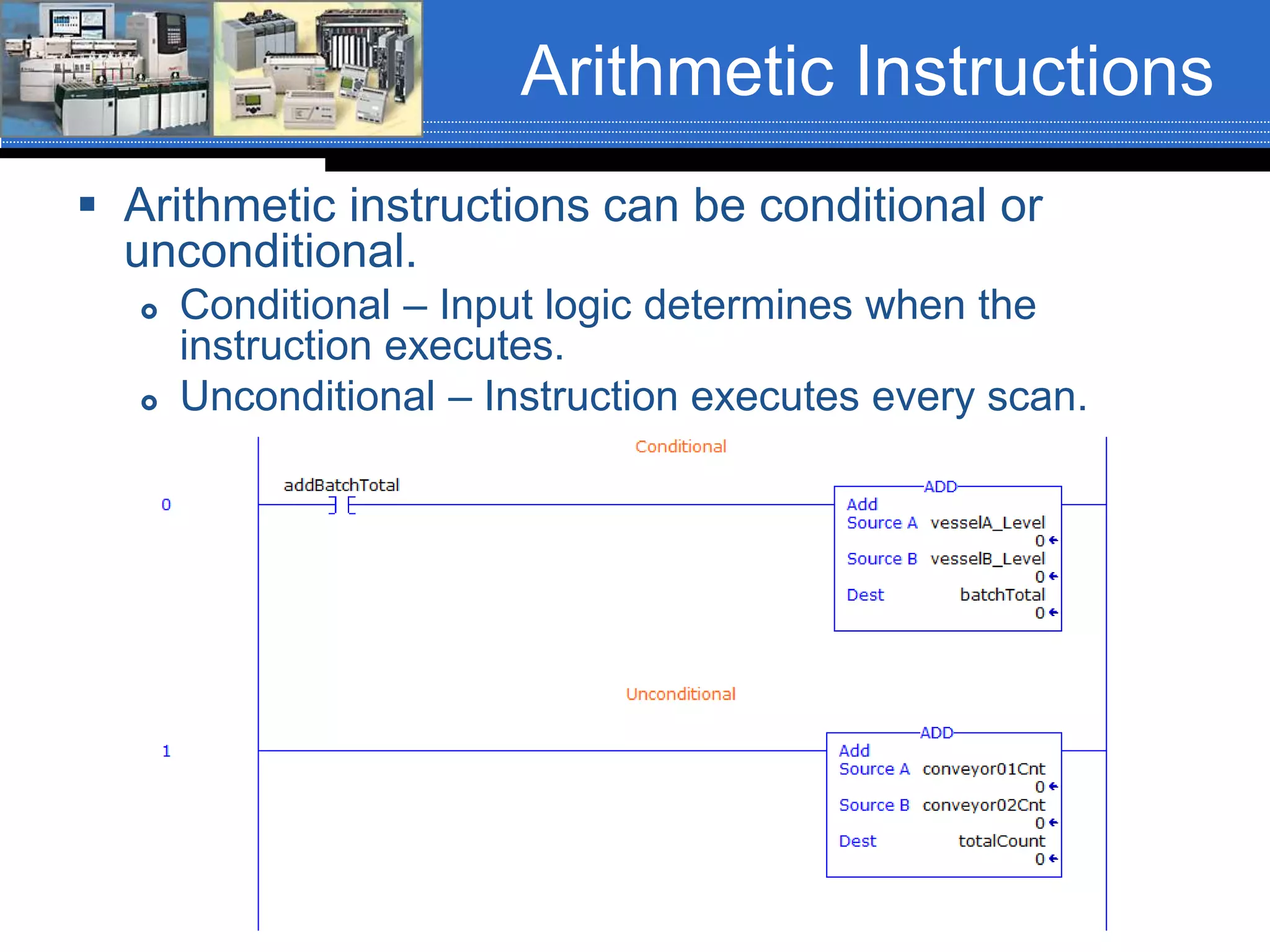
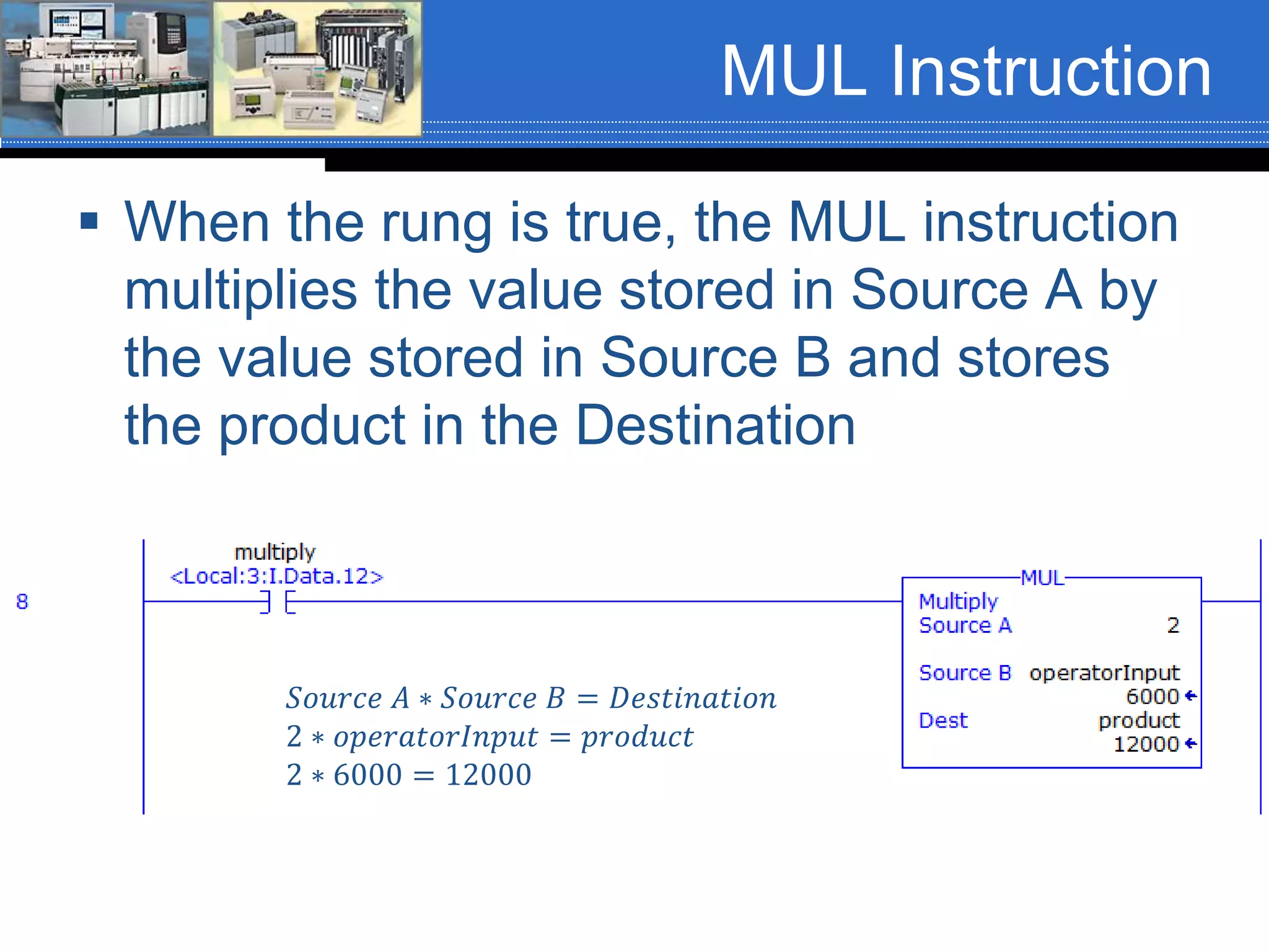
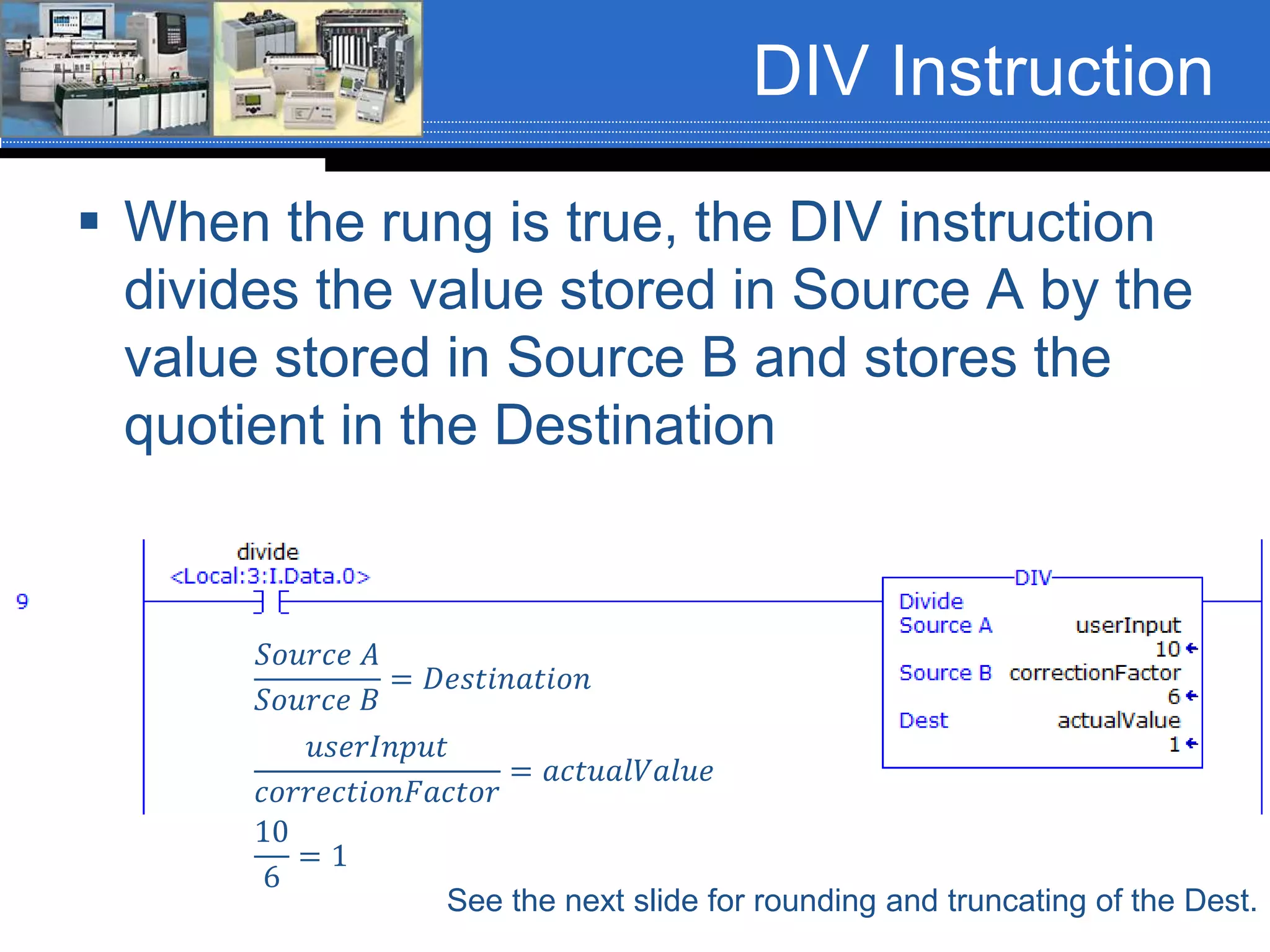
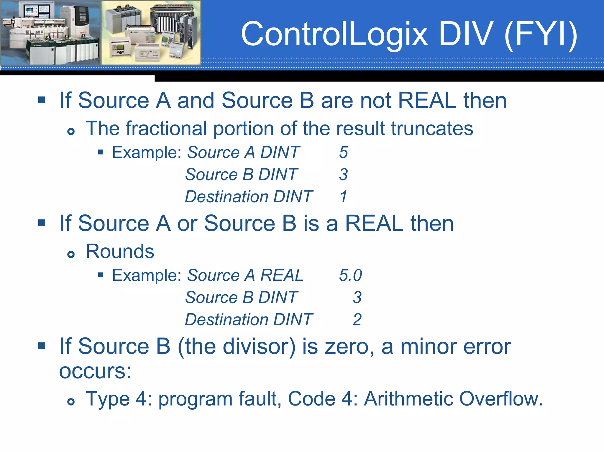
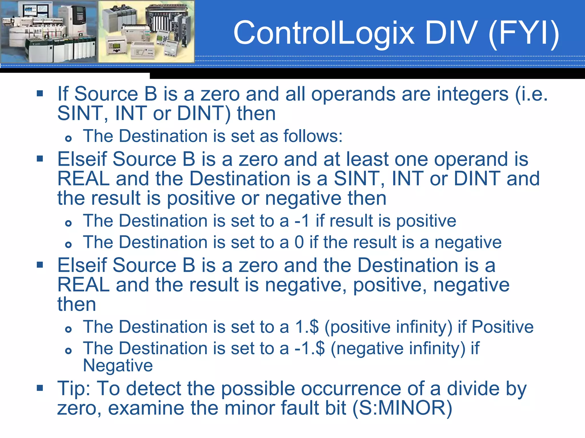
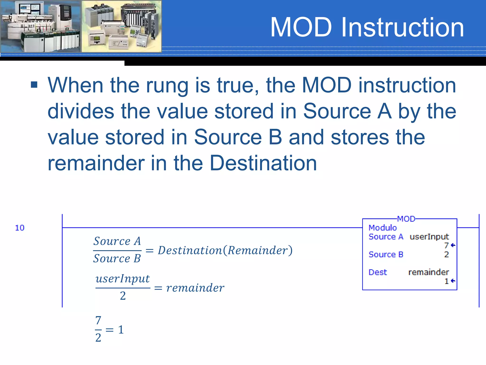
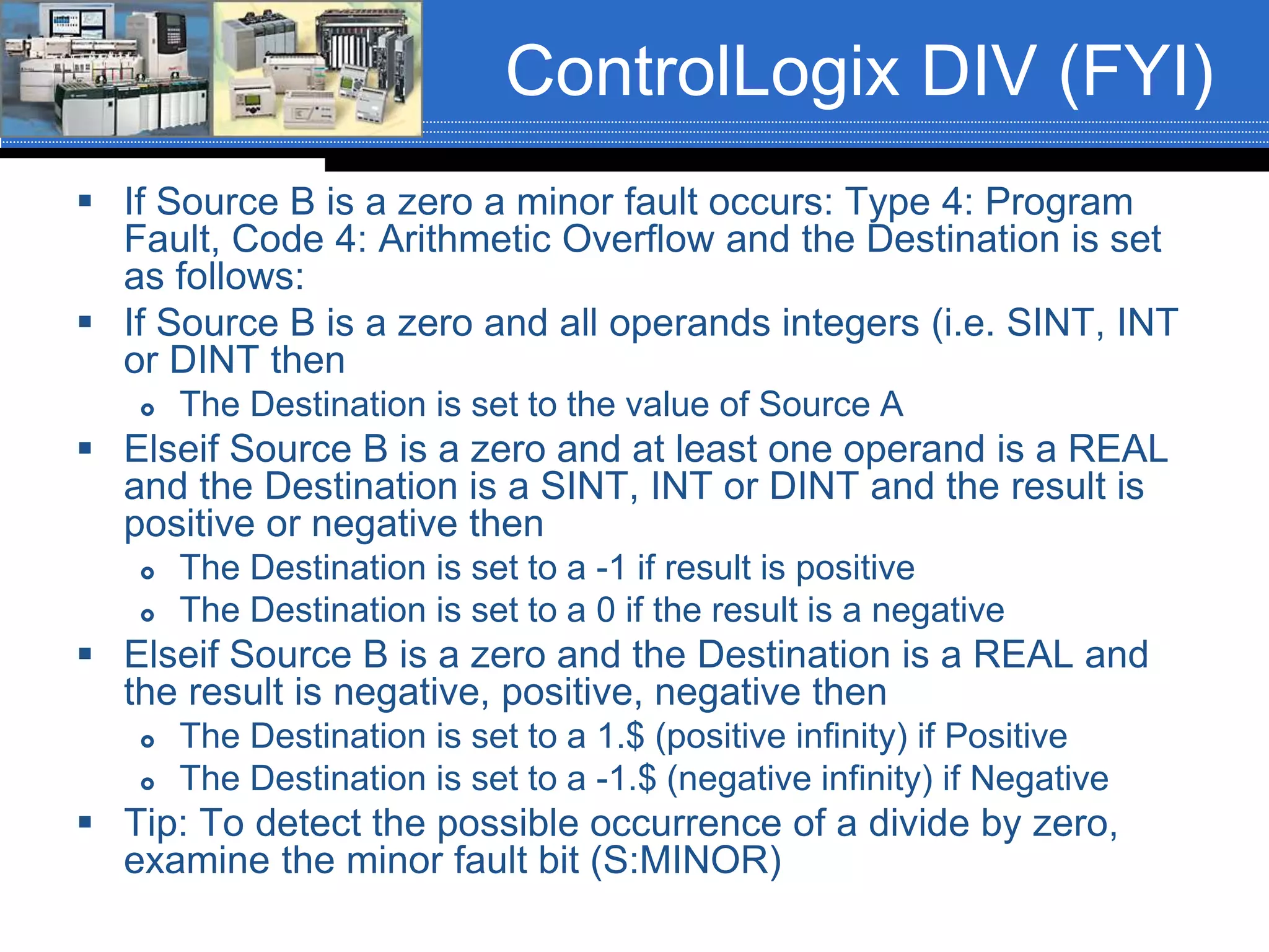
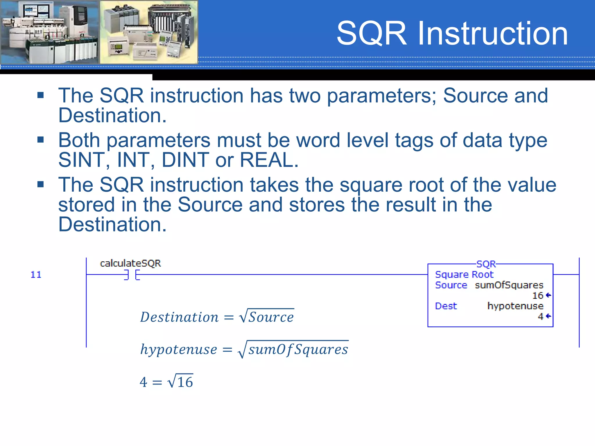
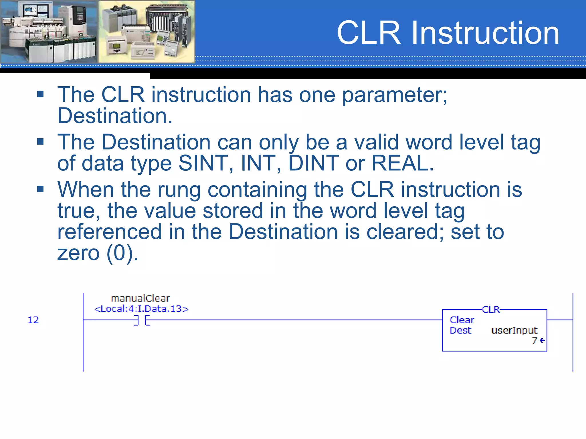
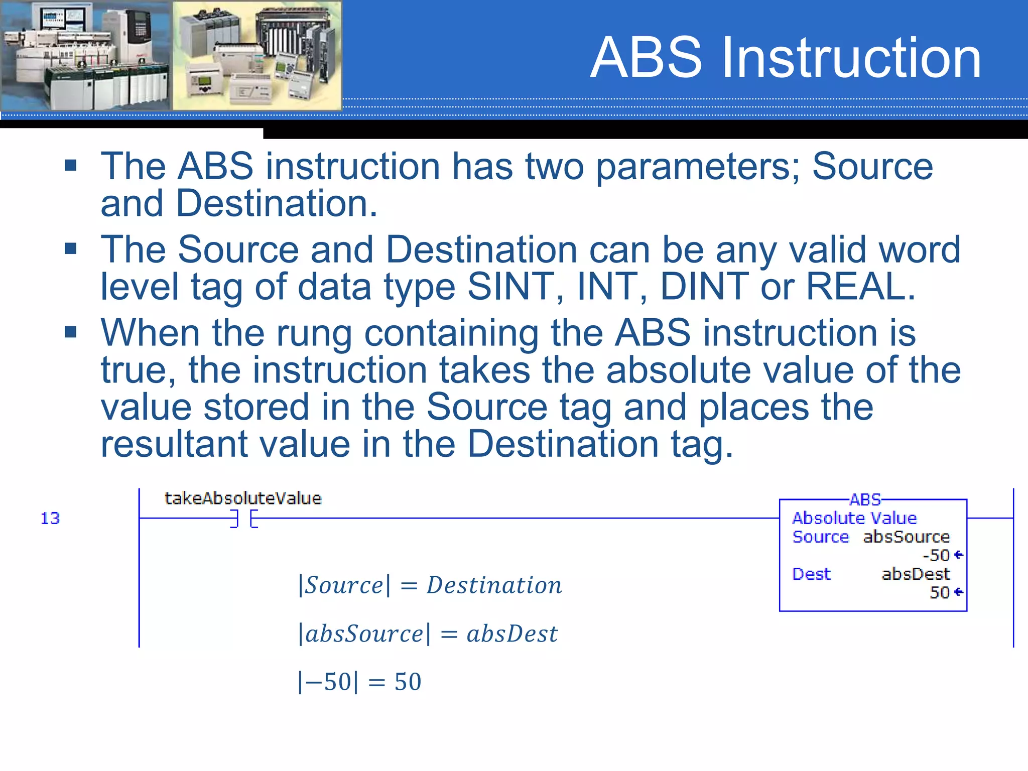
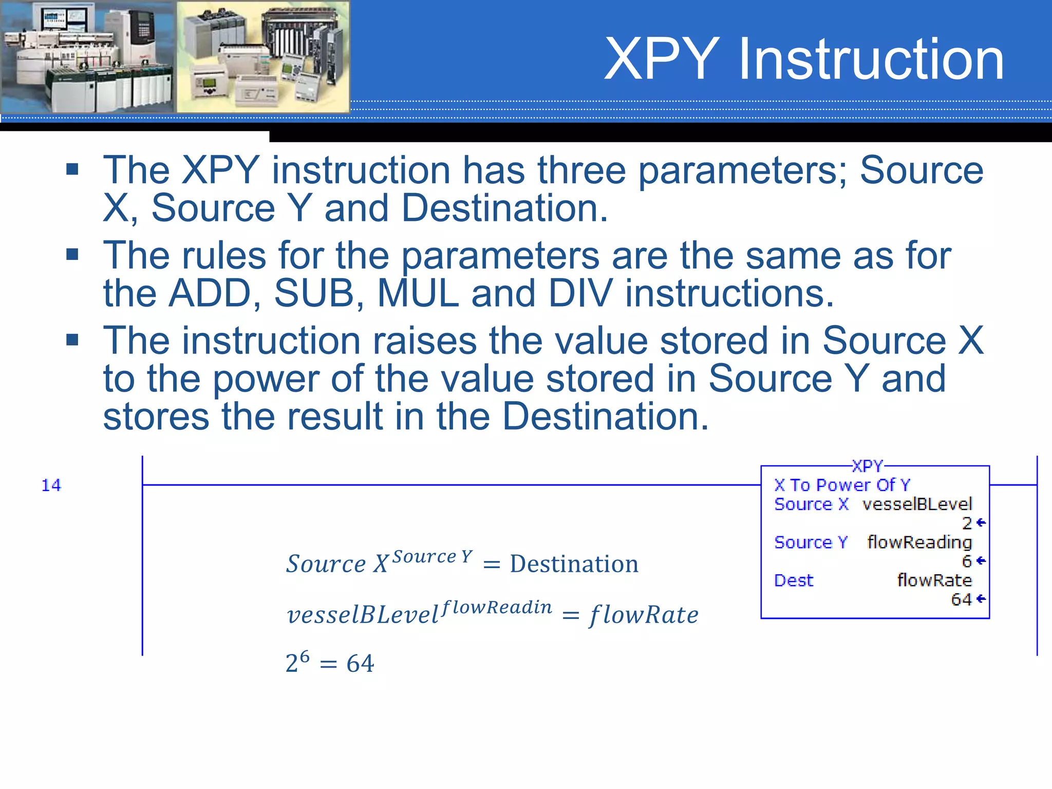
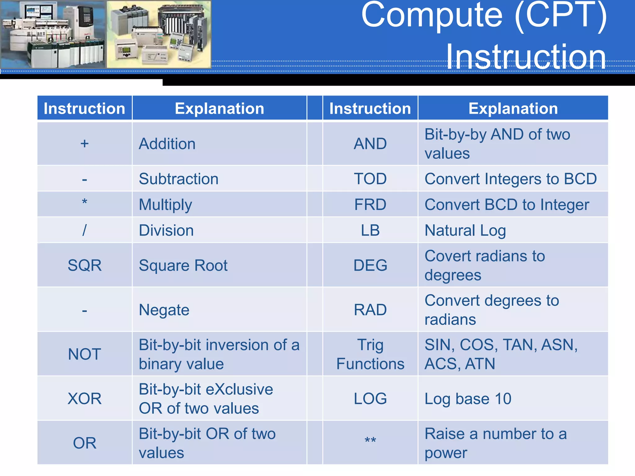
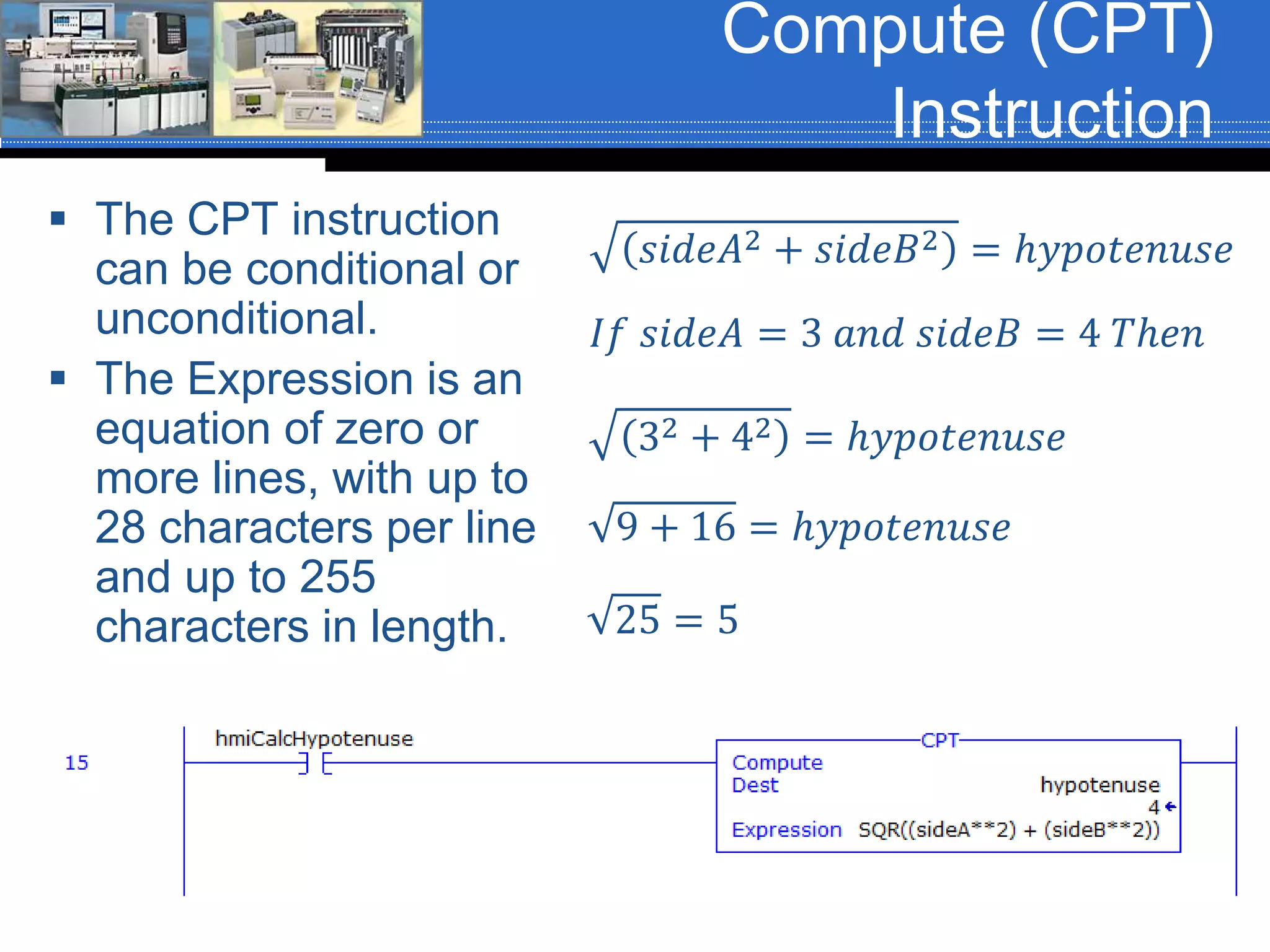
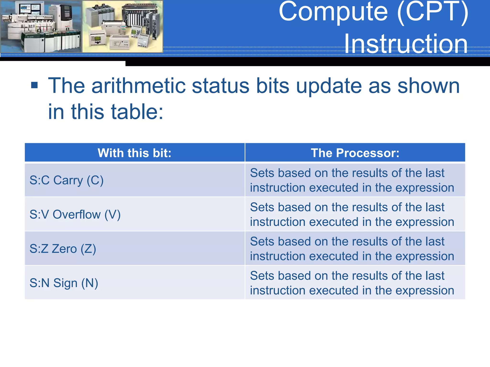
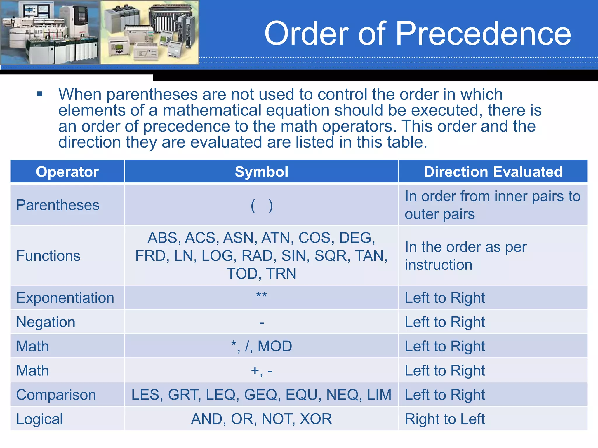
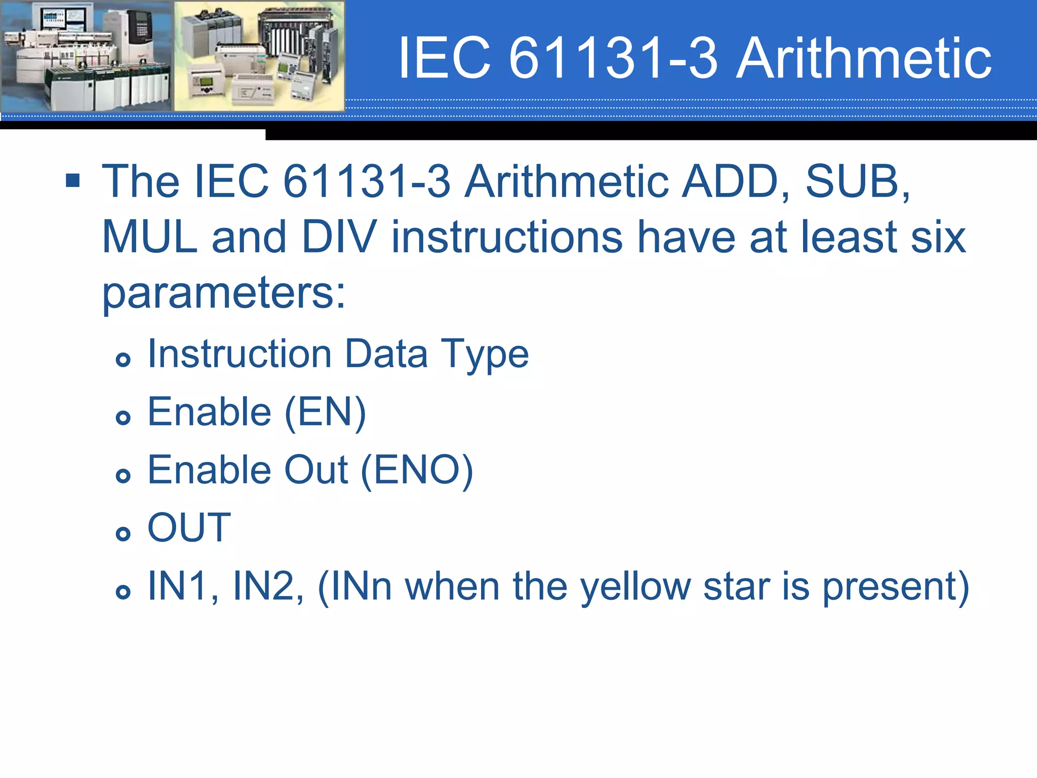
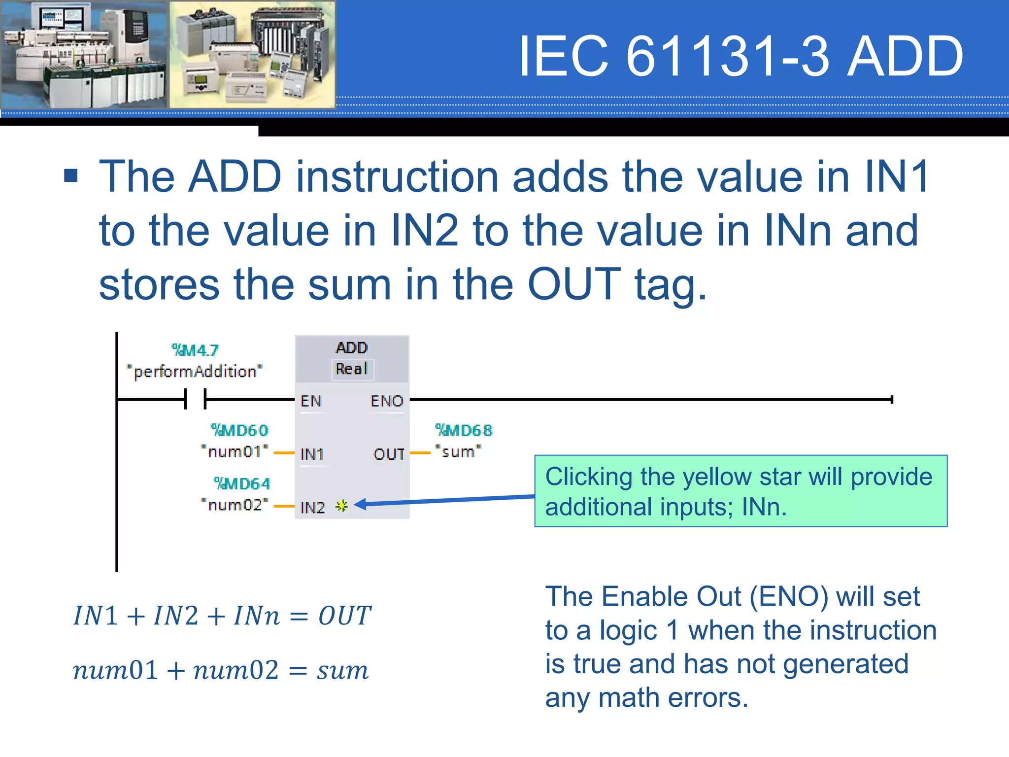
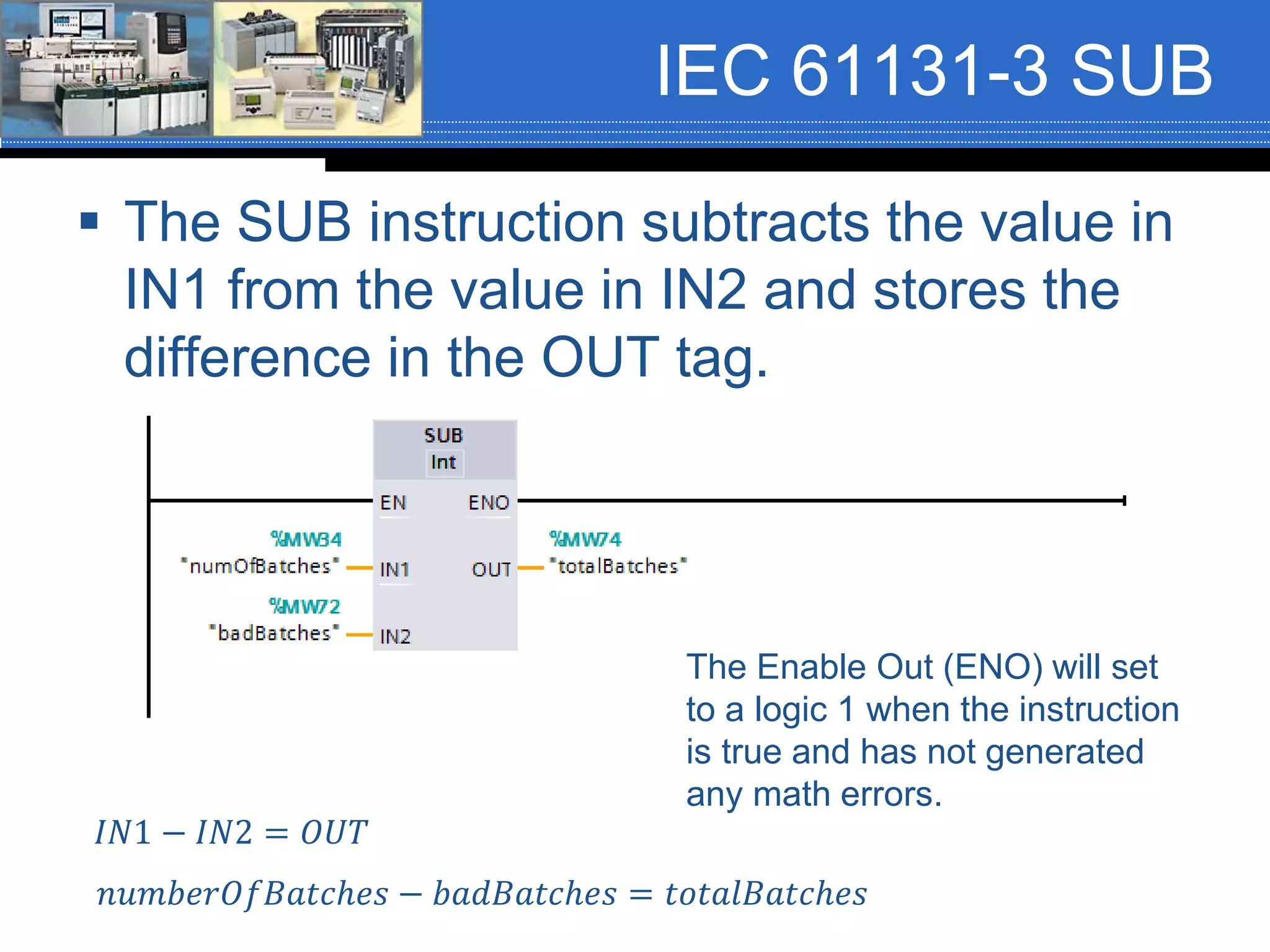
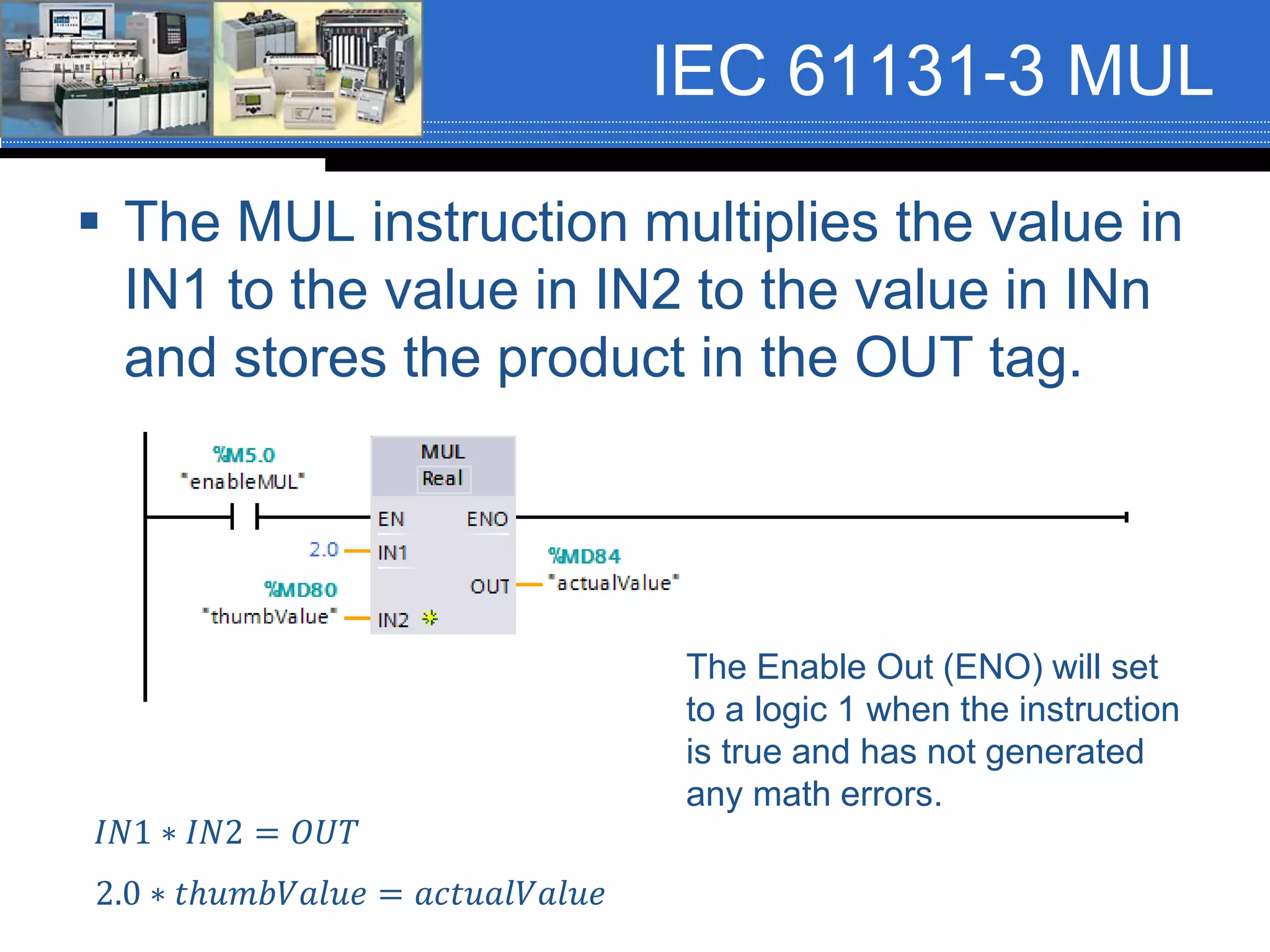
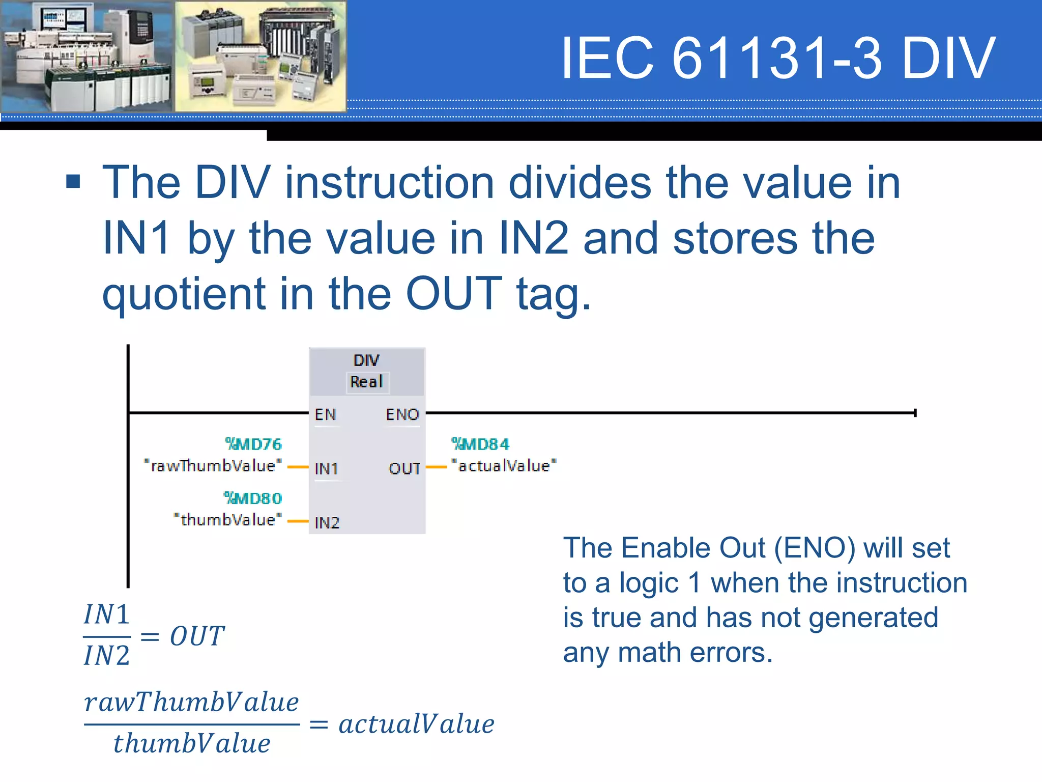
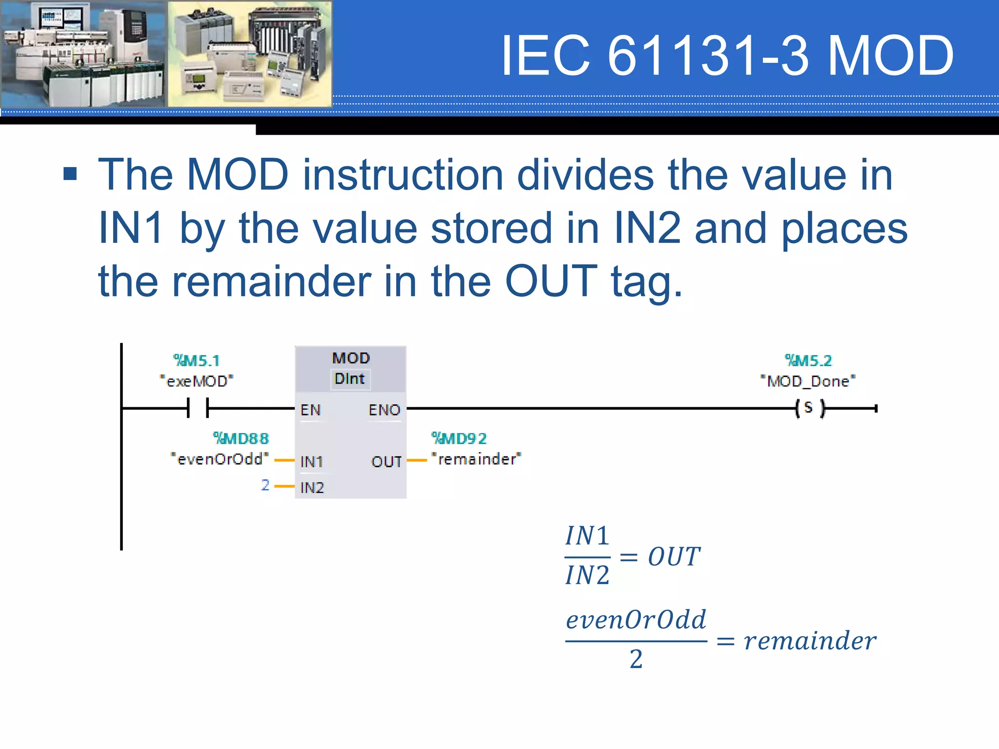
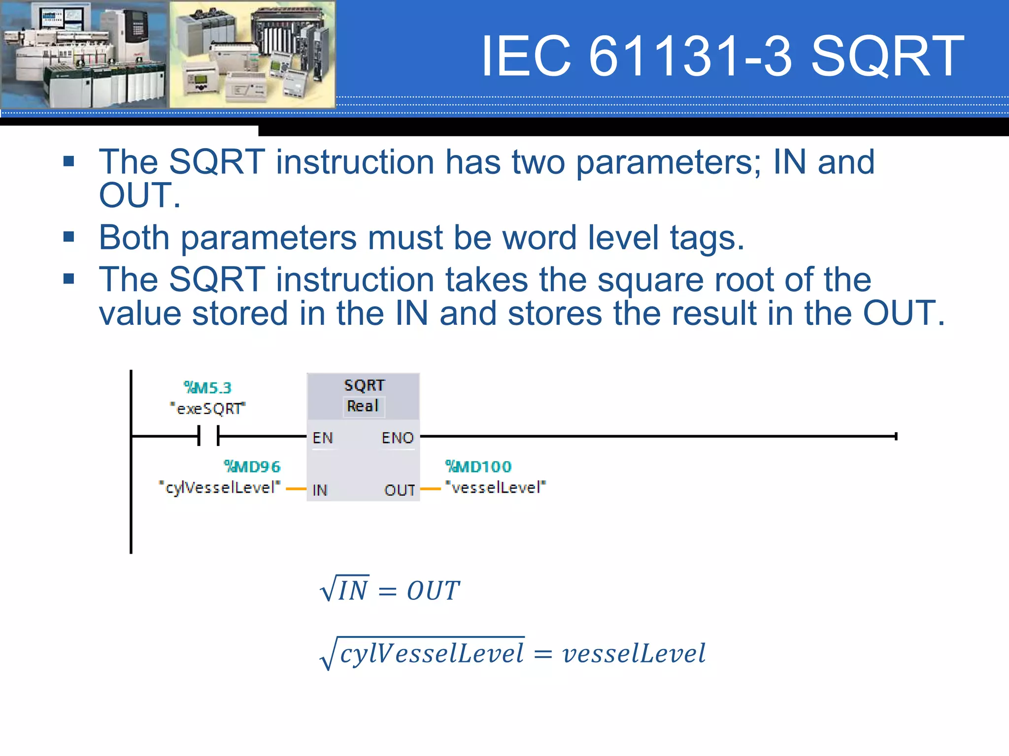
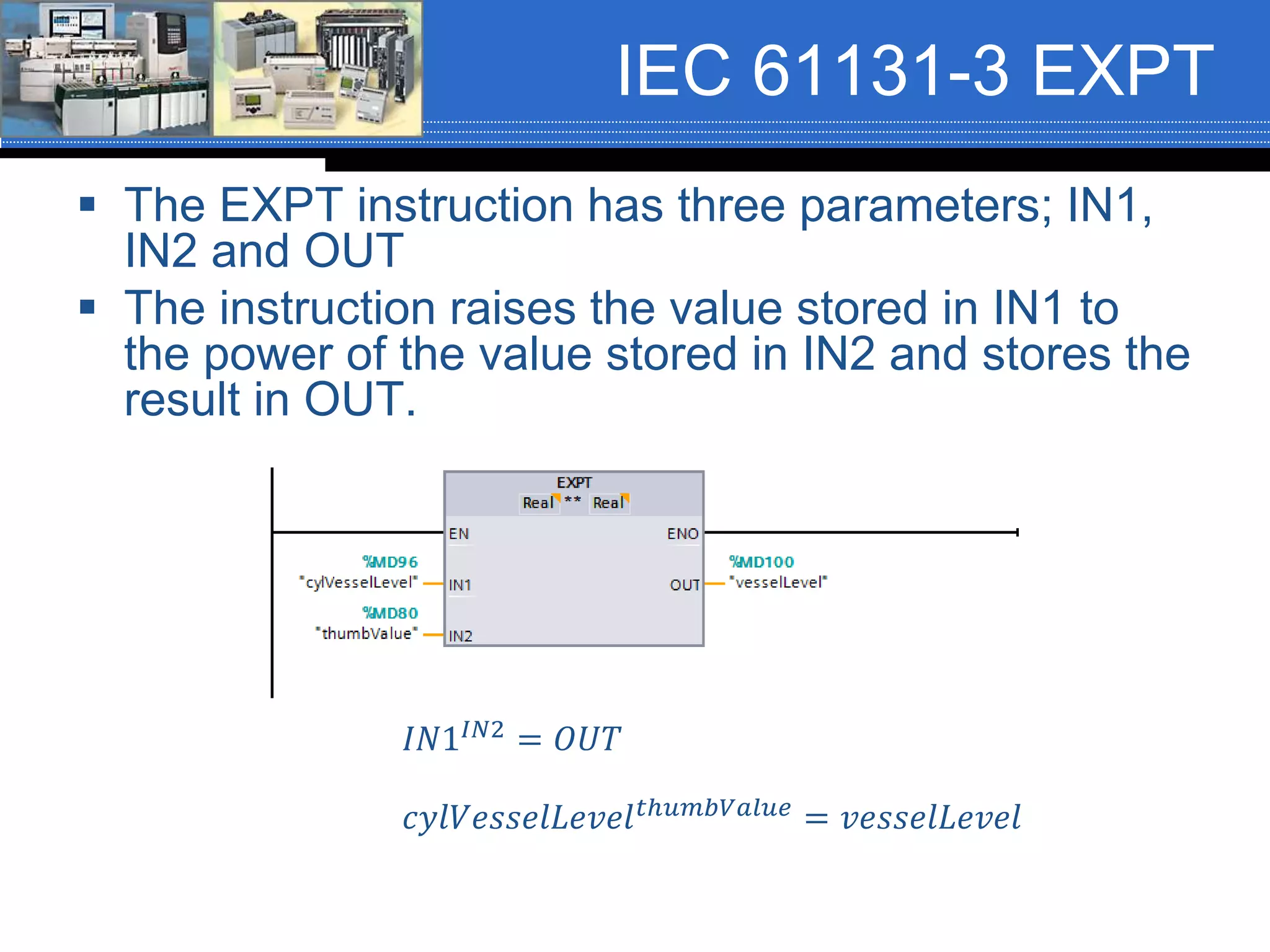
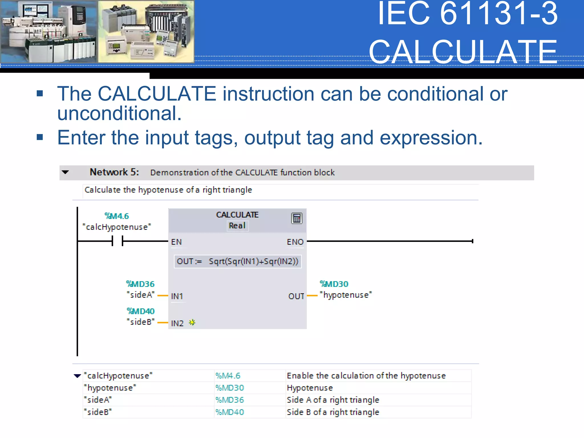
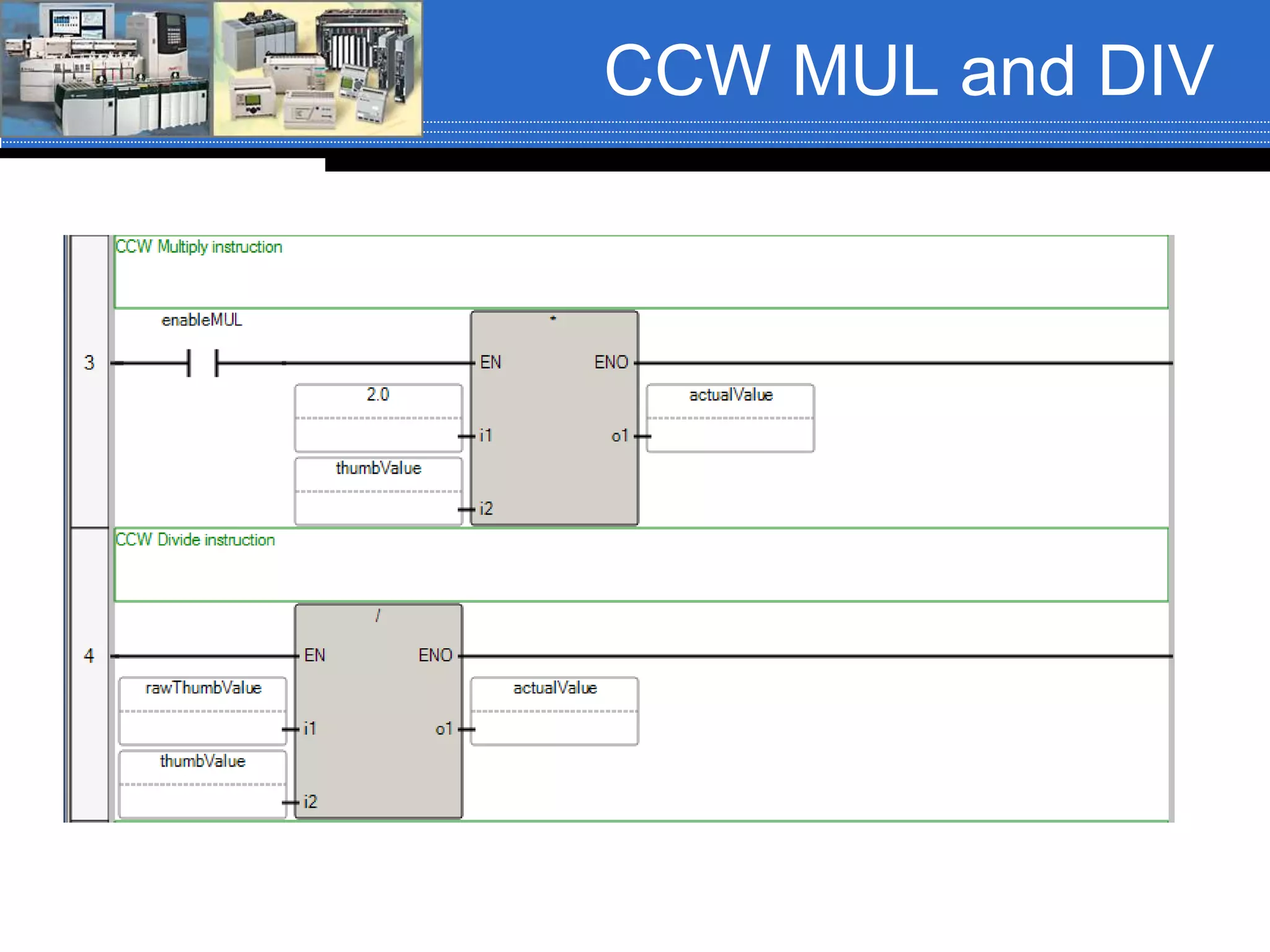
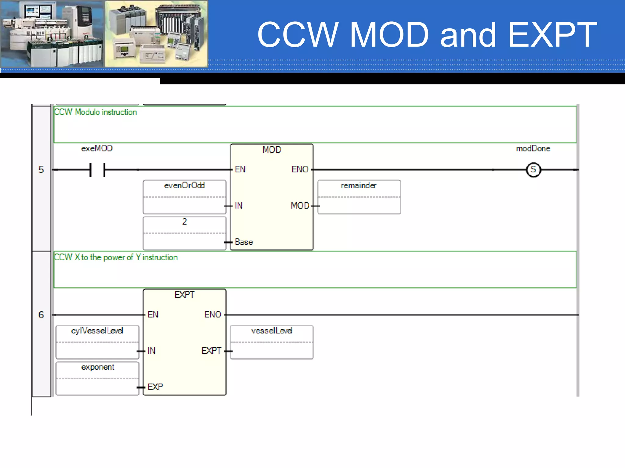
Chapter 06 – Arithmetic
Instructions
And supplemental material
Arithmetic Instructions
Mnemonic Name Mnemonic Name
ADD1 Addition SIN Sine
SUB1 Subtraction COS Cosine
MUL1 Multiply TAN Tangent
DIV1 Divide ASN Arc Sine
MOD1 Modulo ACS Arc Cosine
SQR1 Square Root ATN Arc Tangent
XPY1 X to the power of Y LN1, 2 Natural Log
NEG1 Negate LOG1, 2 Log Base 10
CLR Clear SQRT Square Root ( only ST)
ABS1, 2 Absolute Value
CPT Compute
Instructions in RED will be covered
1. Also available in Function Block Diagram.
2. Also available in Structured Text
All are available in LAD except SQRT (ST only)
ControlLogix Arithmetic
Instructions
 Math instructions are output instructions,
therefore they are placed against the right
power rail.
 The basic math instructions; ADD, SUB,
MUL and DIV have three parameters:
 Source A
 Source B
 Destination (Dest)
Basic Arithmetic
Instructions
 The three parameters have the following rules:
1. Source A and Source B can be tags of data type
SINT, INT, DINT or REAL.
2. Source A can be a program constant and
Source B can be a tag of data type SINT, INT,
DINT or REAL
3. Source B can be a program constant and
Source A can be a tag of data type SINT, INT,
DINT or REAL.
4. Source A and Source B cannot both be program
constants.
5. The Destination (Dest) is always a tag of data
type SINT, INT, DINT or REAL.
Arithmetic Instructions
 Arithmetic instructions can be conditional or
unconditional.
 Conditional – Input logic determines when the
instruction executes.
 Unconditional – Instruction executes every scan.
ADD Instruction
 When the rung is true, the ADD instruction
adds the value stored in Source A to the
value stored in Source B and stores the
sum in the Destination
𝑆𝑜𝑢𝑟𝑐𝑒 𝐴 + 𝑆𝑜𝑢𝑟𝑐𝑒 𝐵 = 𝐷𝑒𝑠𝑡𝑖𝑛𝑎𝑡𝑖𝑜𝑛
𝑣𝑒𝑠𝑠𝑒𝑙𝐴_𝐿𝑒𝑣𝑒𝑙 + vesselB_Level = batchTotal
367 + 780 = 1147
Arithmetic Status Bits
 There are four arithmetic status bits. All of the math
instructions share the same four bits.
 These bits will contain the status of the last math
instruction that is executed.
Status Bit Name Description
S:C Carry (C) Bit is set to a logic 1 if a carry is generated; otherwise it is
cleared to a logic 0.
S:V Overflow (V) Bit is set to a logic 1 if the result or value of the math
instruction does not fit into the destination. Minimum and
maximum values are determined by the data type of the
Destination tag; otherwise it is cleared to a logic 0
S:Z Zero (Z) Bit is set to a logic 1 if the result or value of the math, move or
logic instruction is zero; otherwise it is cleared to a logic 0.
S:N Sign (S) Bit is set to a logic 1 if the result or value after a math, move or
logic instruction is a negative (less than zero) value; otherwise
it is cleared to a logic 0. (This bit should not be confused with
the sign bit, bit 31 of a 32-bit word).
Status Bit Example
 The status bits
will contain the
status of the last
math instruction
that is executed.
Therefore, in the
example shown,
that status of the
Square Root
(SQR)
instruction.
SUB Instruction
 When the rung is true, the SUB instruction
subtracts the value stored in Source A
from the value stored in Source B and
stores the difference in the Destination
𝑆𝑜𝑢𝑟𝑐𝑒 𝐴 − 𝑆𝑜𝑢𝑟𝑐𝑒 𝐵 = 𝐷𝑒𝑠𝑡𝑖𝑛𝑎𝑡𝑖𝑜𝑛
𝑛𝑢𝑚𝑏𝑒𝑟𝑂𝑓𝐵𝑎𝑡𝑐ℎ𝑒𝑠. 𝐴𝐶𝐶 − 𝑏𝑎𝑑𝐵𝑎𝑡𝑐ℎ𝑒𝑠. 𝐴𝐶𝐶 = 𝑡𝑜𝑡𝑎𝑙𝐵𝑎𝑡𝑐ℎ𝑒𝑠
50 − 2 = 48
MUL Instruction
 When the rung is true, the MUL instruction
multiplies the value stored in Source A by
the value stored in Source B and stores
the product in the Destination
𝑆𝑜𝑢𝑟𝑐𝑒 𝐴 ∗ 𝑆𝑜𝑢𝑟𝑐𝑒 𝐵 = 𝐷𝑒𝑠𝑡𝑖𝑛𝑎𝑡𝑖𝑜𝑛
2 ∗ 𝑜𝑝𝑒𝑟𝑎𝑡𝑜𝑟𝐼𝑛𝑝𝑢𝑡 = 𝑝𝑟𝑜𝑑𝑢𝑐𝑡
2 ∗ 6000 = 12000
DIV Instruction
 When the rung is true, the DIV instruction
divides the value stored in Source A by the
value stored in Source B and stores the
quotient in the Destination
𝑆𝑜𝑢𝑟𝑐𝑒 𝐴
𝑆𝑜𝑢𝑟𝑐𝑒 𝐵
= 𝐷𝑒𝑠𝑡𝑖𝑛𝑎𝑡𝑖𝑜𝑛
See the next slide for rounding and truncating of the Dest.
𝑢𝑠𝑒𝑟𝐼𝑛𝑝𝑢𝑡
𝑐𝑜𝑟𝑟𝑒𝑐𝑡𝑖𝑜𝑛𝐹𝑎𝑐𝑡𝑜𝑟
= 𝑎𝑐𝑡𝑢𝑎𝑙𝑉𝑎𝑙𝑢𝑒
10
6
= 1
ControlLogix DIV (FYI)
 If Source A and Source B are not REAL then
 The fractional portion of the result truncates
 Example: Source A DINT 5
Source B DINT 3
Destination DINT 1
 If Source A or Source B is a REAL then
 Rounds
 Example: Source A REAL 5.0
Source B DINT 3
Destination DINT 2
 If Source B (the divisor) is zero, a minor error
occurs:
 Type 4: program fault, Code 4: Arithmetic Overflow.
ControlLogix DIV (FYI)
 If Source B is a zero and all operands are integers (i.e.
SINT, INT or DINT) then
 The Destination is set as follows:
 Elseif Source B is a zero and at least one operand is
REAL and the Destination is a SINT, INT or DINT and
the result is positive or negative then
 The Destination is set to a -1 if result is positive
 The Destination is set to a 0 if the result is a negative
 Elseif Source B is a zero and the Destination is a
REAL and the result is negative, positive, negative
then
 The Destination is set to a 1.$ (positive infinity) if Positive
 The Destination is set to a -1.$ (negative infinity) if
Negative
 Tip: To detect the possible occurrence of a divide by
zero, examine the minor fault bit (S:MINOR)
MOD Instruction
 When the rung is true, the MOD instruction
divides the value stored in Source A by the
value stored in Source B and stores the
remainder in the Destination
𝑆𝑜𝑢𝑟𝑐𝑒 𝐴
𝑆𝑜𝑢𝑟𝑐𝑒 𝐵
= 𝐷𝑒𝑠𝑡𝑖𝑛𝑎𝑡𝑖𝑜𝑛 𝑅𝑒𝑚𝑎𝑖𝑛𝑑𝑒𝑟
𝑢𝑠𝑒𝑟𝐼𝑛𝑝𝑢𝑡
2
= 𝑟𝑒𝑚𝑎𝑖𝑛𝑑𝑒𝑟
7
2
= 1
ControlLogix DIV (FYI)
 If Source B is a zero a minor fault occurs: Type 4: Program
Fault, Code 4: Arithmetic Overflow and the Destination is set
as follows:
 If Source B is a zero and all operands integers (i.e. SINT, INT
or DINT then
 The Destination is set to the value of Source A
 Elseif Source B is a zero and at least one operand is a REAL
and the Destination is a SINT, INT or DINT and the result is
positive or negative then
 The Destination is set to a -1 if result is positive
 The Destination is set to a 0 if the result is a negative
 Elseif Source B is a zero and the Destination is a REAL and
the result is negative, positive, negative then
 The Destination is set to a 1.$ (positive infinity) if Positive
 The Destination is set to a -1.$ (negative infinity) if Negative
 Tip: To detect the possible occurrence of a divide by zero,
examine the minor fault bit (S:MINOR)
SQR Instruction
 The SQR instruction has two parameters; Source and
Destination.
 Both parameters must be word level tags of data type
SINT, INT, DINT or REAL.
 The SQR instruction takes the square root of the value
stored in the Source and stores the result in the
Destination.
ℎ𝑦𝑝𝑜𝑡𝑒𝑛𝑢𝑠𝑒 = 𝑠𝑢𝑚𝑂𝑓𝑆𝑞𝑢𝑎𝑟𝑒𝑠
𝐷𝑒𝑠𝑡𝑖𝑛𝑎𝑡𝑖𝑜𝑛 = 𝑆𝑜𝑢𝑟𝑐𝑒
4 = 16
CLR Instruction
 The CLR instruction has one parameter;
Destination.
 The Destination can only be a valid word level tag
of data type SINT, INT, DINT or REAL.
 When the rung containing the CLR instruction is
true, the value stored in the word level tag
referenced in the Destination is cleared; set to
zero (0).
ABS Instruction
 The ABS instruction has two parameters; Source
and Destination.
 The Source and Destination can be any valid word
level tag of data type SINT, INT, DINT or REAL.
 When the rung containing the ABS instruction is
true, the instruction takes the absolute value of the
value stored in the Source tag and places the
resultant value in the Destination tag.
𝑆𝑜𝑢𝑟𝑐𝑒 = 𝐷𝑒𝑠𝑡𝑖𝑛𝑎𝑡𝑖𝑜𝑛
𝑎𝑏𝑠𝑆𝑜𝑢𝑟𝑐𝑒 = 𝑎𝑏𝑠𝐷𝑒𝑠𝑡
−50 = 50
XPY Instruction
 The XPY instruction has three parameters; Source
X, Source Y and Destination.
 The rules for the parameters are the same as for
the ADD, SUB, MUL and DIV instructions.
 The instruction raises the value stored in Source X
to the power of the value stored in Source Y and
stores the result in the Destination.
𝑣𝑒𝑠𝑠𝑒𝑙𝐵𝐿𝑒𝑣𝑒𝑙 𝑓𝑙𝑜𝑤𝑅𝑒𝑎𝑑𝑖𝑛
= 𝑓𝑙𝑜𝑤𝑅𝑎𝑡𝑒
𝑆𝑜𝑢𝑟𝑐𝑒 𝑋 𝑆𝑜𝑢𝑟𝑐𝑒 𝑌 = Destination
26
= 64
Compute (CPT)
Instruction
 The Compute (CPT) instruction is an
output instruction. It has two parameters:
 Destination
 Expression
 The Destination can be any valid word
level tag of data type SINT, INT, DINT or
REAL.
 The Expression can contain any valid
expression (equation) that needs to be
solved.
Compute (CPT)
Instruction
 The Compute (CPT) instruction can perform
any or all of the following operations:
 Copy
 Arithmetic
 Logical
 Conversion
 The operation(s) is/are defined in the
Expression and the result of the Expression
is stored in the tag referenced in the
Destination.
Compute (CPT)
Instruction
Instruction Explanation Instruction Explanation
+ Addition AND
Bit-by-by AND of two
values
- Subtraction TOD Convert Integers to BCD
* Multiply FRD Convert BCD to Integer
/ Division LB Natural Log
SQR Square Root DEG
Covert radians to
degrees
- Negate RAD
Convert degrees to
radians
NOT
Bit-by-bit inversion of a
binary value
Trig
Functions
SIN, COS, TAN, ASN,
ACS, ATN
XOR
Bit-by-bit eXclusive
OR of two values
LOG Log base 10
OR
Bit-by-bit OR of two
values
**
Raise a number to a
power
Compute (CPT)
Instruction
 The CPT instruction
can be conditional or
unconditional.
 The Expression is an
equation of zero or
more lines, with up to
28 characters per line
and up to 255
characters in length.
𝑠𝑖𝑑𝑒𝐴2 + 𝑠𝑖𝑑𝑒𝐵2 = ℎ𝑦𝑝𝑜𝑡𝑒𝑛𝑢𝑠𝑒
𝐼𝑓 𝑠𝑖𝑑𝑒𝐴 = 3 𝑎𝑛𝑑 𝑠𝑖𝑑𝑒𝐵 = 4 𝑇ℎ𝑒𝑛
32 + 42 = ℎ𝑦𝑝𝑜𝑡𝑒𝑛𝑢𝑠𝑒
9 + 16 = ℎ𝑦𝑝𝑜𝑡𝑒𝑛𝑢𝑠𝑒
25 = 5
Compute (CPT)
Instruction
 The arithmetic status bits update as shown
in this table:
With this bit: The Processor:
S:C Carry (C)
Sets based on the results of the last
instruction executed in the expression
S:V Overflow (V)
Sets based on the results of the last
instruction executed in the expression
S:Z Zero (Z)
Sets based on the results of the last
instruction executed in the expression
S:N Sign (N)
Sets based on the results of the last
instruction executed in the expression
Order of Precedence
 When parentheses are not used to control the order in which
elements of a mathematical equation should be executed, there is
an order of precedence to the math operators. This order and the
direction they are evaluated are listed in this table.
Operator Symbol Direction Evaluated
Parentheses ( )
In order from inner pairs to
outer pairs
Functions
ABS, ACS, ASN, ATN, COS, DEG,
FRD, LN, LOG, RAD, SIN, SQR, TAN,
TOD, TRN
In the order as per
instruction
Exponentiation ** Left to Right
Negation - Left to Right
Math *, /, MOD Left to Right
Math +, - Left to Right
Comparison LES, GRT, LEQ, GEQ, EQU, NEQ, LIM Left to Right
Logical AND, OR, NOT, XOR Right to Left
Order of Precedence
 Example of Order of Precedence:
Equation to Evaluate
15 + 60 / 3 – 4 * 5 + 7
Evaluate from left to right
Division and multiplication have higher
precedence than addition and subtraction
60 / 3 = 20
4 * 5 = 20
15 + 20 – 20 = 7
15 + 7 = 22
 15 + 60 / 3 – 4 * 5 + 7 = 22
Order of Precedence
 Example of Order of Precedence:
Equation to Evaluate
25 * 2 + 4 / 2 * 6 – 45 + 16 / 8
Evaluate from left to right
Division and multiplication have higher precedence than
addition and subtraction
 25 * 2 = 50
4 / 2 * 6 = 2 * 6 = 12
16 / 8 = 2
50 + 12 – 45 + 2
62 – 45 + 2
17 + 2 = 19
 25 * 2 + 4 / 2 * 6 – 45 + 16 / 8 = 19
IEC 61131-3 Arithmetic
 The IEC 61131-3 Arithmetic ADD, SUB,
MUL and DIV instructions have at least six
parameters:
 Instruction Data Type
 Enable (EN)
 Enable Out (ENO)
 OUT
 IN1, IN2, (INn when the yellow star is present)
IEC 61131-3 ADD
 The ADD instruction adds the value in IN1
to the value in IN2 to the value in INn and
stores the sum in the OUT tag.
𝐼𝑁1 + 𝐼𝑁2 + 𝐼𝑁𝑛 = 𝑂𝑈𝑇
𝑛𝑢𝑚01 + 𝑛𝑢𝑚02 = 𝑠𝑢𝑚
The Enable Out (ENO) will set
to a logic 1 when the instruction
is true and has not generated
any math errors.
Clicking the yellow star will provide
additional inputs; INn.
IEC 61131-3 SUB
 The SUB instruction subtracts the value in
IN1 from the value in IN2 and stores the
difference in the OUT tag.
𝐼𝑁1 − 𝐼𝑁2 = 𝑂𝑈𝑇
𝑛𝑢𝑚𝑏𝑒𝑟𝑂𝑓𝐵𝑎𝑡𝑐ℎ𝑒𝑠 − 𝑏𝑎𝑑𝐵𝑎𝑡𝑐ℎ𝑒𝑠 = 𝑡𝑜𝑡𝑎𝑙𝐵𝑎𝑡𝑐ℎ𝑒𝑠
The Enable Out (ENO) will set
to a logic 1 when the instruction
is true and has not generated
any math errors.
IEC 61131-3 MUL
 The MUL instruction multiplies the value in
IN1 to the value in IN2 to the value in INn
and stores the product in the OUT tag.
𝐼𝑁1 ∗ 𝐼𝑁2 = 𝑂𝑈𝑇
2.0 ∗ 𝑡ℎ𝑢𝑚𝑏𝑉𝑎𝑙𝑢𝑒 = 𝑎𝑐𝑡𝑢𝑎𝑙𝑉𝑎𝑙𝑢𝑒
The Enable Out (ENO) will set
to a logic 1 when the instruction
is true and has not generated
any math errors.
IEC 61131-3 DIV
 The DIV instruction divides the value in
IN1 by the value in IN2 and stores the
quotient in the OUT tag.
𝐼𝑁1
𝐼𝑁2
= 𝑂𝑈𝑇
𝑟𝑎𝑤𝑇ℎ𝑢𝑚𝑏𝑉𝑎𝑙𝑢𝑒
𝑡ℎ𝑢𝑚𝑏𝑉𝑎𝑙𝑢𝑒
= 𝑎𝑐𝑡𝑢𝑎𝑙𝑉𝑎𝑙𝑢𝑒
The Enable Out (ENO) will set
to a logic 1 when the instruction
is true and has not generated
any math errors.
IEC 61131-3 MOD
 The MOD instruction divides the value in
IN1 by the value stored in IN2 and places
the remainder in the OUT tag.
𝐼𝑁1
𝐼𝑁2
= 𝑂𝑈𝑇
𝑒𝑣𝑒𝑛𝑂𝑟𝑂𝑑𝑑
2
= 𝑟𝑒𝑚𝑎𝑖𝑛𝑑𝑒𝑟
IEC 61131-3 SQRT
 The SQRT instruction has two parameters; IN and
OUT.
 Both parameters must be word level tags.
 The SQRT instruction takes the square root of the
value stored in the IN and stores the result in the OUT.
𝐼𝑁 = 𝑂𝑈𝑇
𝑐𝑦𝑙𝑉𝑒𝑠𝑠𝑒𝑙𝐿𝑒𝑣𝑒𝑙 = 𝑣𝑒𝑠𝑠𝑒𝑙𝐿𝑒𝑣𝑒𝑙
IEC 61131-3 EXPT
 The EXPT instruction has three parameters; IN1,
IN2 and OUT
 The instruction raises the value stored in IN1 to
the power of the value stored in IN2 and stores the
result in OUT.
𝐼𝑁1𝐼𝑁2 = 𝑂𝑈𝑇
𝑐𝑦𝑙𝑉𝑒𝑠𝑠𝑒𝑙𝐿𝑒𝑣𝑒𝑙 𝑡ℎ𝑢𝑚𝑏𝑉𝑎𝑙𝑢𝑒 = 𝑣𝑒𝑠𝑠𝑒𝑙𝐿𝑒𝑣𝑒𝑙
IEC 61131-3
CALCULATE
 The CALCULATE instruction can be conditional or
unconditional.
 Enter the input tags, output tag and expression.
AB CCW Arithmetic
 The AB CCW also uses IEC 61131-3
arithmetic instruction.
 The CCW does not have a CPT or
CALCULATE instruction; however, any
complex expressions can be performed in
structured text.
 The following slides show the CCW
instructions referenced in this
presentation.
CCW ADD and SUB
CCW MUL and DIV
CCW MOD and EXPT

Math cl ccw_siemens_rev01_fa16

  • 1.
    Chapter 06 –Arithmetic Instructions And supplemental material
  • 2.
    Arithmetic Instructions Mnemonic NameMnemonic Name ADD1 Addition SIN Sine SUB1 Subtraction COS Cosine MUL1 Multiply TAN Tangent DIV1 Divide ASN Arc Sine MOD1 Modulo ACS Arc Cosine SQR1 Square Root ATN Arc Tangent XPY1 X to the power of Y LN1, 2 Natural Log NEG1 Negate LOG1, 2 Log Base 10 CLR Clear SQRT Square Root ( only ST) ABS1, 2 Absolute Value CPT Compute Instructions in RED will be covered 1. Also available in Function Block Diagram. 2. Also available in Structured Text All are available in LAD except SQRT (ST only)
  • 3.
    ControlLogix Arithmetic Instructions  Mathinstructions are output instructions, therefore they are placed against the right power rail.  The basic math instructions; ADD, SUB, MUL and DIV have three parameters:  Source A  Source B  Destination (Dest)
  • 4.
    Basic Arithmetic Instructions  Thethree parameters have the following rules: 1. Source A and Source B can be tags of data type SINT, INT, DINT or REAL. 2. Source A can be a program constant and Source B can be a tag of data type SINT, INT, DINT or REAL 3. Source B can be a program constant and Source A can be a tag of data type SINT, INT, DINT or REAL. 4. Source A and Source B cannot both be program constants. 5. The Destination (Dest) is always a tag of data type SINT, INT, DINT or REAL.
  • 5.
    Arithmetic Instructions  Arithmeticinstructions can be conditional or unconditional.  Conditional – Input logic determines when the instruction executes.  Unconditional – Instruction executes every scan.
  • 6.
    ADD Instruction  Whenthe rung is true, the ADD instruction adds the value stored in Source A to the value stored in Source B and stores the sum in the Destination 𝑆𝑜𝑢𝑟𝑐𝑒 𝐴 + 𝑆𝑜𝑢𝑟𝑐𝑒 𝐵 = 𝐷𝑒𝑠𝑡𝑖𝑛𝑎𝑡𝑖𝑜𝑛 𝑣𝑒𝑠𝑠𝑒𝑙𝐴_𝐿𝑒𝑣𝑒𝑙 + vesselB_Level = batchTotal 367 + 780 = 1147
  • 7.
    Arithmetic Status Bits There are four arithmetic status bits. All of the math instructions share the same four bits.  These bits will contain the status of the last math instruction that is executed. Status Bit Name Description S:C Carry (C) Bit is set to a logic 1 if a carry is generated; otherwise it is cleared to a logic 0. S:V Overflow (V) Bit is set to a logic 1 if the result or value of the math instruction does not fit into the destination. Minimum and maximum values are determined by the data type of the Destination tag; otherwise it is cleared to a logic 0 S:Z Zero (Z) Bit is set to a logic 1 if the result or value of the math, move or logic instruction is zero; otherwise it is cleared to a logic 0. S:N Sign (S) Bit is set to a logic 1 if the result or value after a math, move or logic instruction is a negative (less than zero) value; otherwise it is cleared to a logic 0. (This bit should not be confused with the sign bit, bit 31 of a 32-bit word).
  • 8.
    Status Bit Example The status bits will contain the status of the last math instruction that is executed. Therefore, in the example shown, that status of the Square Root (SQR) instruction.
  • 9.
    SUB Instruction  Whenthe rung is true, the SUB instruction subtracts the value stored in Source A from the value stored in Source B and stores the difference in the Destination 𝑆𝑜𝑢𝑟𝑐𝑒 𝐴 − 𝑆𝑜𝑢𝑟𝑐𝑒 𝐵 = 𝐷𝑒𝑠𝑡𝑖𝑛𝑎𝑡𝑖𝑜𝑛 𝑛𝑢𝑚𝑏𝑒𝑟𝑂𝑓𝐵𝑎𝑡𝑐ℎ𝑒𝑠. 𝐴𝐶𝐶 − 𝑏𝑎𝑑𝐵𝑎𝑡𝑐ℎ𝑒𝑠. 𝐴𝐶𝐶 = 𝑡𝑜𝑡𝑎𝑙𝐵𝑎𝑡𝑐ℎ𝑒𝑠 50 − 2 = 48
  • 10.
    MUL Instruction  Whenthe rung is true, the MUL instruction multiplies the value stored in Source A by the value stored in Source B and stores the product in the Destination 𝑆𝑜𝑢𝑟𝑐𝑒 𝐴 ∗ 𝑆𝑜𝑢𝑟𝑐𝑒 𝐵 = 𝐷𝑒𝑠𝑡𝑖𝑛𝑎𝑡𝑖𝑜𝑛 2 ∗ 𝑜𝑝𝑒𝑟𝑎𝑡𝑜𝑟𝐼𝑛𝑝𝑢𝑡 = 𝑝𝑟𝑜𝑑𝑢𝑐𝑡 2 ∗ 6000 = 12000
  • 11.
    DIV Instruction  Whenthe rung is true, the DIV instruction divides the value stored in Source A by the value stored in Source B and stores the quotient in the Destination 𝑆𝑜𝑢𝑟𝑐𝑒 𝐴 𝑆𝑜𝑢𝑟𝑐𝑒 𝐵 = 𝐷𝑒𝑠𝑡𝑖𝑛𝑎𝑡𝑖𝑜𝑛 See the next slide for rounding and truncating of the Dest. 𝑢𝑠𝑒𝑟𝐼𝑛𝑝𝑢𝑡 𝑐𝑜𝑟𝑟𝑒𝑐𝑡𝑖𝑜𝑛𝐹𝑎𝑐𝑡𝑜𝑟 = 𝑎𝑐𝑡𝑢𝑎𝑙𝑉𝑎𝑙𝑢𝑒 10 6 = 1
  • 12.
    ControlLogix DIV (FYI) If Source A and Source B are not REAL then  The fractional portion of the result truncates  Example: Source A DINT 5 Source B DINT 3 Destination DINT 1  If Source A or Source B is a REAL then  Rounds  Example: Source A REAL 5.0 Source B DINT 3 Destination DINT 2  If Source B (the divisor) is zero, a minor error occurs:  Type 4: program fault, Code 4: Arithmetic Overflow.
  • 13.
    ControlLogix DIV (FYI) If Source B is a zero and all operands are integers (i.e. SINT, INT or DINT) then  The Destination is set as follows:  Elseif Source B is a zero and at least one operand is REAL and the Destination is a SINT, INT or DINT and the result is positive or negative then  The Destination is set to a -1 if result is positive  The Destination is set to a 0 if the result is a negative  Elseif Source B is a zero and the Destination is a REAL and the result is negative, positive, negative then  The Destination is set to a 1.$ (positive infinity) if Positive  The Destination is set to a -1.$ (negative infinity) if Negative  Tip: To detect the possible occurrence of a divide by zero, examine the minor fault bit (S:MINOR)
  • 14.
    MOD Instruction  Whenthe rung is true, the MOD instruction divides the value stored in Source A by the value stored in Source B and stores the remainder in the Destination 𝑆𝑜𝑢𝑟𝑐𝑒 𝐴 𝑆𝑜𝑢𝑟𝑐𝑒 𝐵 = 𝐷𝑒𝑠𝑡𝑖𝑛𝑎𝑡𝑖𝑜𝑛 𝑅𝑒𝑚𝑎𝑖𝑛𝑑𝑒𝑟 𝑢𝑠𝑒𝑟𝐼𝑛𝑝𝑢𝑡 2 = 𝑟𝑒𝑚𝑎𝑖𝑛𝑑𝑒𝑟 7 2 = 1
  • 15.
    ControlLogix DIV (FYI) If Source B is a zero a minor fault occurs: Type 4: Program Fault, Code 4: Arithmetic Overflow and the Destination is set as follows:  If Source B is a zero and all operands integers (i.e. SINT, INT or DINT then  The Destination is set to the value of Source A  Elseif Source B is a zero and at least one operand is a REAL and the Destination is a SINT, INT or DINT and the result is positive or negative then  The Destination is set to a -1 if result is positive  The Destination is set to a 0 if the result is a negative  Elseif Source B is a zero and the Destination is a REAL and the result is negative, positive, negative then  The Destination is set to a 1.$ (positive infinity) if Positive  The Destination is set to a -1.$ (negative infinity) if Negative  Tip: To detect the possible occurrence of a divide by zero, examine the minor fault bit (S:MINOR)
  • 16.
    SQR Instruction  TheSQR instruction has two parameters; Source and Destination.  Both parameters must be word level tags of data type SINT, INT, DINT or REAL.  The SQR instruction takes the square root of the value stored in the Source and stores the result in the Destination. ℎ𝑦𝑝𝑜𝑡𝑒𝑛𝑢𝑠𝑒 = 𝑠𝑢𝑚𝑂𝑓𝑆𝑞𝑢𝑎𝑟𝑒𝑠 𝐷𝑒𝑠𝑡𝑖𝑛𝑎𝑡𝑖𝑜𝑛 = 𝑆𝑜𝑢𝑟𝑐𝑒 4 = 16
  • 17.
    CLR Instruction  TheCLR instruction has one parameter; Destination.  The Destination can only be a valid word level tag of data type SINT, INT, DINT or REAL.  When the rung containing the CLR instruction is true, the value stored in the word level tag referenced in the Destination is cleared; set to zero (0).
  • 18.
    ABS Instruction  TheABS instruction has two parameters; Source and Destination.  The Source and Destination can be any valid word level tag of data type SINT, INT, DINT or REAL.  When the rung containing the ABS instruction is true, the instruction takes the absolute value of the value stored in the Source tag and places the resultant value in the Destination tag. 𝑆𝑜𝑢𝑟𝑐𝑒 = 𝐷𝑒𝑠𝑡𝑖𝑛𝑎𝑡𝑖𝑜𝑛 𝑎𝑏𝑠𝑆𝑜𝑢𝑟𝑐𝑒 = 𝑎𝑏𝑠𝐷𝑒𝑠𝑡 −50 = 50
  • 19.
    XPY Instruction  TheXPY instruction has three parameters; Source X, Source Y and Destination.  The rules for the parameters are the same as for the ADD, SUB, MUL and DIV instructions.  The instruction raises the value stored in Source X to the power of the value stored in Source Y and stores the result in the Destination. 𝑣𝑒𝑠𝑠𝑒𝑙𝐵𝐿𝑒𝑣𝑒𝑙 𝑓𝑙𝑜𝑤𝑅𝑒𝑎𝑑𝑖𝑛 = 𝑓𝑙𝑜𝑤𝑅𝑎𝑡𝑒 𝑆𝑜𝑢𝑟𝑐𝑒 𝑋 𝑆𝑜𝑢𝑟𝑐𝑒 𝑌 = Destination 26 = 64
  • 20.
    Compute (CPT) Instruction  TheCompute (CPT) instruction is an output instruction. It has two parameters:  Destination  Expression  The Destination can be any valid word level tag of data type SINT, INT, DINT or REAL.  The Expression can contain any valid expression (equation) that needs to be solved.
  • 21.
    Compute (CPT) Instruction  TheCompute (CPT) instruction can perform any or all of the following operations:  Copy  Arithmetic  Logical  Conversion  The operation(s) is/are defined in the Expression and the result of the Expression is stored in the tag referenced in the Destination.
  • 22.
    Compute (CPT) Instruction Instruction ExplanationInstruction Explanation + Addition AND Bit-by-by AND of two values - Subtraction TOD Convert Integers to BCD * Multiply FRD Convert BCD to Integer / Division LB Natural Log SQR Square Root DEG Covert radians to degrees - Negate RAD Convert degrees to radians NOT Bit-by-bit inversion of a binary value Trig Functions SIN, COS, TAN, ASN, ACS, ATN XOR Bit-by-bit eXclusive OR of two values LOG Log base 10 OR Bit-by-bit OR of two values ** Raise a number to a power
  • 23.
    Compute (CPT) Instruction  TheCPT instruction can be conditional or unconditional.  The Expression is an equation of zero or more lines, with up to 28 characters per line and up to 255 characters in length. 𝑠𝑖𝑑𝑒𝐴2 + 𝑠𝑖𝑑𝑒𝐵2 = ℎ𝑦𝑝𝑜𝑡𝑒𝑛𝑢𝑠𝑒 𝐼𝑓 𝑠𝑖𝑑𝑒𝐴 = 3 𝑎𝑛𝑑 𝑠𝑖𝑑𝑒𝐵 = 4 𝑇ℎ𝑒𝑛 32 + 42 = ℎ𝑦𝑝𝑜𝑡𝑒𝑛𝑢𝑠𝑒 9 + 16 = ℎ𝑦𝑝𝑜𝑡𝑒𝑛𝑢𝑠𝑒 25 = 5
  • 24.
    Compute (CPT) Instruction  Thearithmetic status bits update as shown in this table: With this bit: The Processor: S:C Carry (C) Sets based on the results of the last instruction executed in the expression S:V Overflow (V) Sets based on the results of the last instruction executed in the expression S:Z Zero (Z) Sets based on the results of the last instruction executed in the expression S:N Sign (N) Sets based on the results of the last instruction executed in the expression
  • 25.
    Order of Precedence When parentheses are not used to control the order in which elements of a mathematical equation should be executed, there is an order of precedence to the math operators. This order and the direction they are evaluated are listed in this table. Operator Symbol Direction Evaluated Parentheses ( ) In order from inner pairs to outer pairs Functions ABS, ACS, ASN, ATN, COS, DEG, FRD, LN, LOG, RAD, SIN, SQR, TAN, TOD, TRN In the order as per instruction Exponentiation ** Left to Right Negation - Left to Right Math *, /, MOD Left to Right Math +, - Left to Right Comparison LES, GRT, LEQ, GEQ, EQU, NEQ, LIM Left to Right Logical AND, OR, NOT, XOR Right to Left
  • 26.
    Order of Precedence Example of Order of Precedence: Equation to Evaluate 15 + 60 / 3 – 4 * 5 + 7 Evaluate from left to right Division and multiplication have higher precedence than addition and subtraction 60 / 3 = 20 4 * 5 = 20 15 + 20 – 20 = 7 15 + 7 = 22  15 + 60 / 3 – 4 * 5 + 7 = 22
  • 27.
    Order of Precedence Example of Order of Precedence: Equation to Evaluate 25 * 2 + 4 / 2 * 6 – 45 + 16 / 8 Evaluate from left to right Division and multiplication have higher precedence than addition and subtraction  25 * 2 = 50 4 / 2 * 6 = 2 * 6 = 12 16 / 8 = 2 50 + 12 – 45 + 2 62 – 45 + 2 17 + 2 = 19  25 * 2 + 4 / 2 * 6 – 45 + 16 / 8 = 19
  • 28.
    IEC 61131-3 Arithmetic The IEC 61131-3 Arithmetic ADD, SUB, MUL and DIV instructions have at least six parameters:  Instruction Data Type  Enable (EN)  Enable Out (ENO)  OUT  IN1, IN2, (INn when the yellow star is present)
  • 29.
    IEC 61131-3 ADD The ADD instruction adds the value in IN1 to the value in IN2 to the value in INn and stores the sum in the OUT tag. 𝐼𝑁1 + 𝐼𝑁2 + 𝐼𝑁𝑛 = 𝑂𝑈𝑇 𝑛𝑢𝑚01 + 𝑛𝑢𝑚02 = 𝑠𝑢𝑚 The Enable Out (ENO) will set to a logic 1 when the instruction is true and has not generated any math errors. Clicking the yellow star will provide additional inputs; INn.
  • 30.
    IEC 61131-3 SUB The SUB instruction subtracts the value in IN1 from the value in IN2 and stores the difference in the OUT tag. 𝐼𝑁1 − 𝐼𝑁2 = 𝑂𝑈𝑇 𝑛𝑢𝑚𝑏𝑒𝑟𝑂𝑓𝐵𝑎𝑡𝑐ℎ𝑒𝑠 − 𝑏𝑎𝑑𝐵𝑎𝑡𝑐ℎ𝑒𝑠 = 𝑡𝑜𝑡𝑎𝑙𝐵𝑎𝑡𝑐ℎ𝑒𝑠 The Enable Out (ENO) will set to a logic 1 when the instruction is true and has not generated any math errors.
  • 31.
    IEC 61131-3 MUL The MUL instruction multiplies the value in IN1 to the value in IN2 to the value in INn and stores the product in the OUT tag. 𝐼𝑁1 ∗ 𝐼𝑁2 = 𝑂𝑈𝑇 2.0 ∗ 𝑡ℎ𝑢𝑚𝑏𝑉𝑎𝑙𝑢𝑒 = 𝑎𝑐𝑡𝑢𝑎𝑙𝑉𝑎𝑙𝑢𝑒 The Enable Out (ENO) will set to a logic 1 when the instruction is true and has not generated any math errors.
  • 32.
    IEC 61131-3 DIV The DIV instruction divides the value in IN1 by the value in IN2 and stores the quotient in the OUT tag. 𝐼𝑁1 𝐼𝑁2 = 𝑂𝑈𝑇 𝑟𝑎𝑤𝑇ℎ𝑢𝑚𝑏𝑉𝑎𝑙𝑢𝑒 𝑡ℎ𝑢𝑚𝑏𝑉𝑎𝑙𝑢𝑒 = 𝑎𝑐𝑡𝑢𝑎𝑙𝑉𝑎𝑙𝑢𝑒 The Enable Out (ENO) will set to a logic 1 when the instruction is true and has not generated any math errors.
  • 33.
    IEC 61131-3 MOD The MOD instruction divides the value in IN1 by the value stored in IN2 and places the remainder in the OUT tag. 𝐼𝑁1 𝐼𝑁2 = 𝑂𝑈𝑇 𝑒𝑣𝑒𝑛𝑂𝑟𝑂𝑑𝑑 2 = 𝑟𝑒𝑚𝑎𝑖𝑛𝑑𝑒𝑟
  • 34.
    IEC 61131-3 SQRT The SQRT instruction has two parameters; IN and OUT.  Both parameters must be word level tags.  The SQRT instruction takes the square root of the value stored in the IN and stores the result in the OUT. 𝐼𝑁 = 𝑂𝑈𝑇 𝑐𝑦𝑙𝑉𝑒𝑠𝑠𝑒𝑙𝐿𝑒𝑣𝑒𝑙 = 𝑣𝑒𝑠𝑠𝑒𝑙𝐿𝑒𝑣𝑒𝑙
  • 35.
    IEC 61131-3 EXPT The EXPT instruction has three parameters; IN1, IN2 and OUT  The instruction raises the value stored in IN1 to the power of the value stored in IN2 and stores the result in OUT. 𝐼𝑁1𝐼𝑁2 = 𝑂𝑈𝑇 𝑐𝑦𝑙𝑉𝑒𝑠𝑠𝑒𝑙𝐿𝑒𝑣𝑒𝑙 𝑡ℎ𝑢𝑚𝑏𝑉𝑎𝑙𝑢𝑒 = 𝑣𝑒𝑠𝑠𝑒𝑙𝐿𝑒𝑣𝑒𝑙
  • 36.
    IEC 61131-3 CALCULATE  TheCALCULATE instruction can be conditional or unconditional.  Enter the input tags, output tag and expression.
  • 37.
    AB CCW Arithmetic The AB CCW also uses IEC 61131-3 arithmetic instruction.  The CCW does not have a CPT or CALCULATE instruction; however, any complex expressions can be performed in structured text.  The following slides show the CCW instructions referenced in this presentation.
  • 38.
  • 39.
  • 40.