Downloaded 156 times
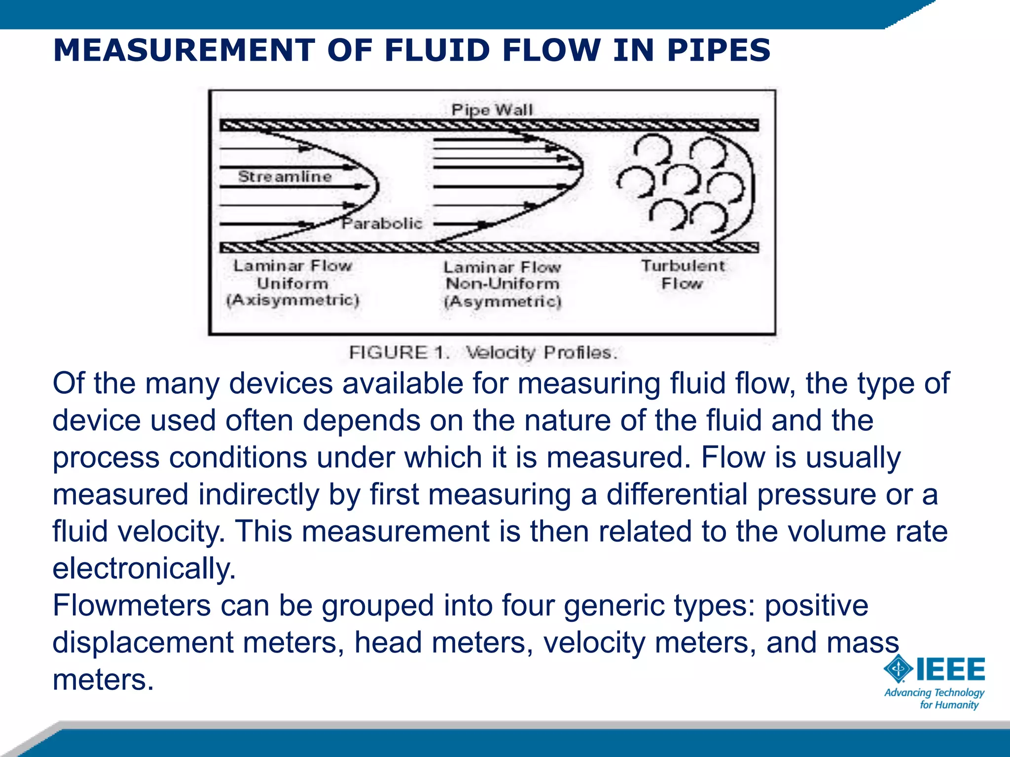
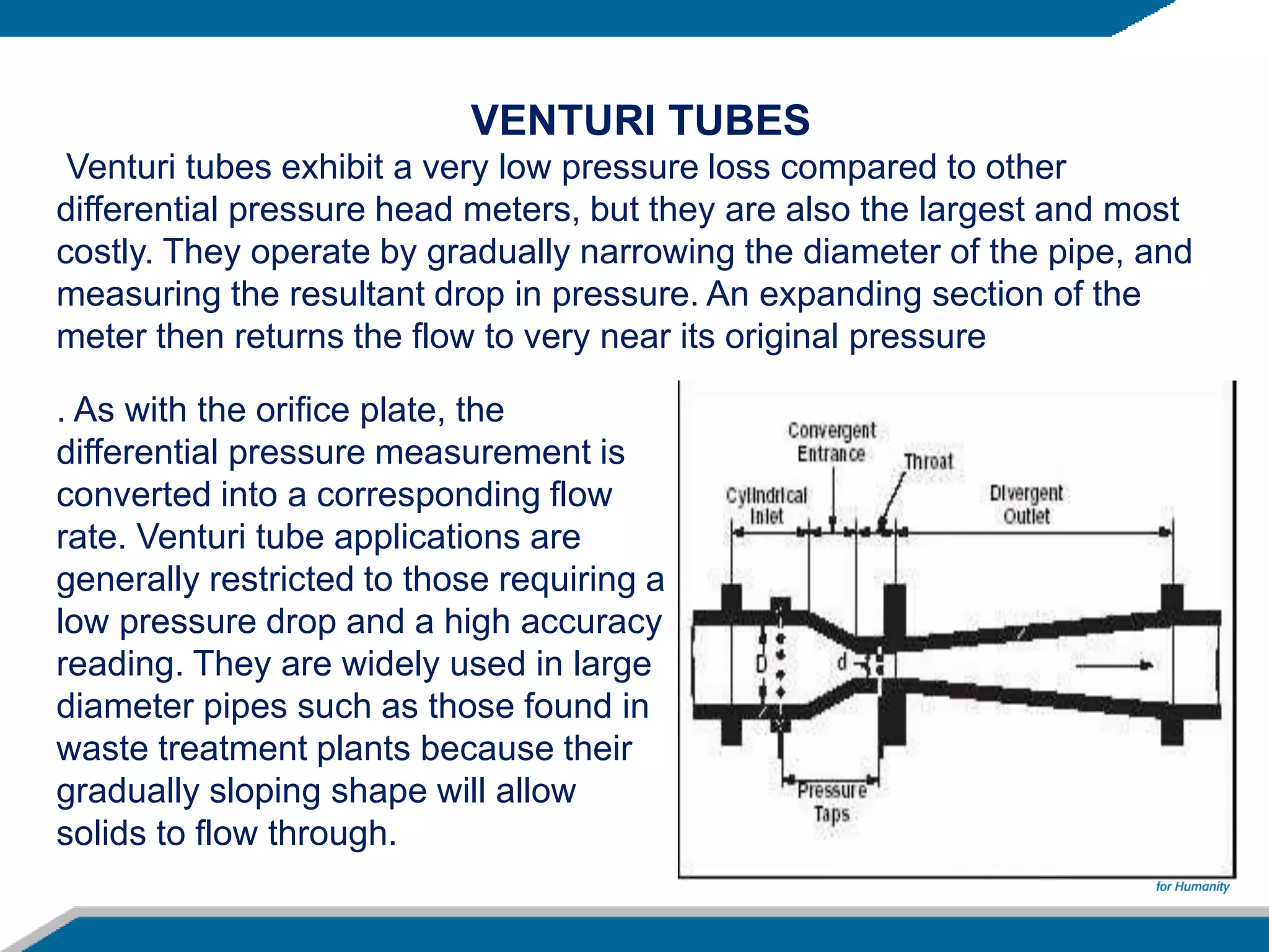
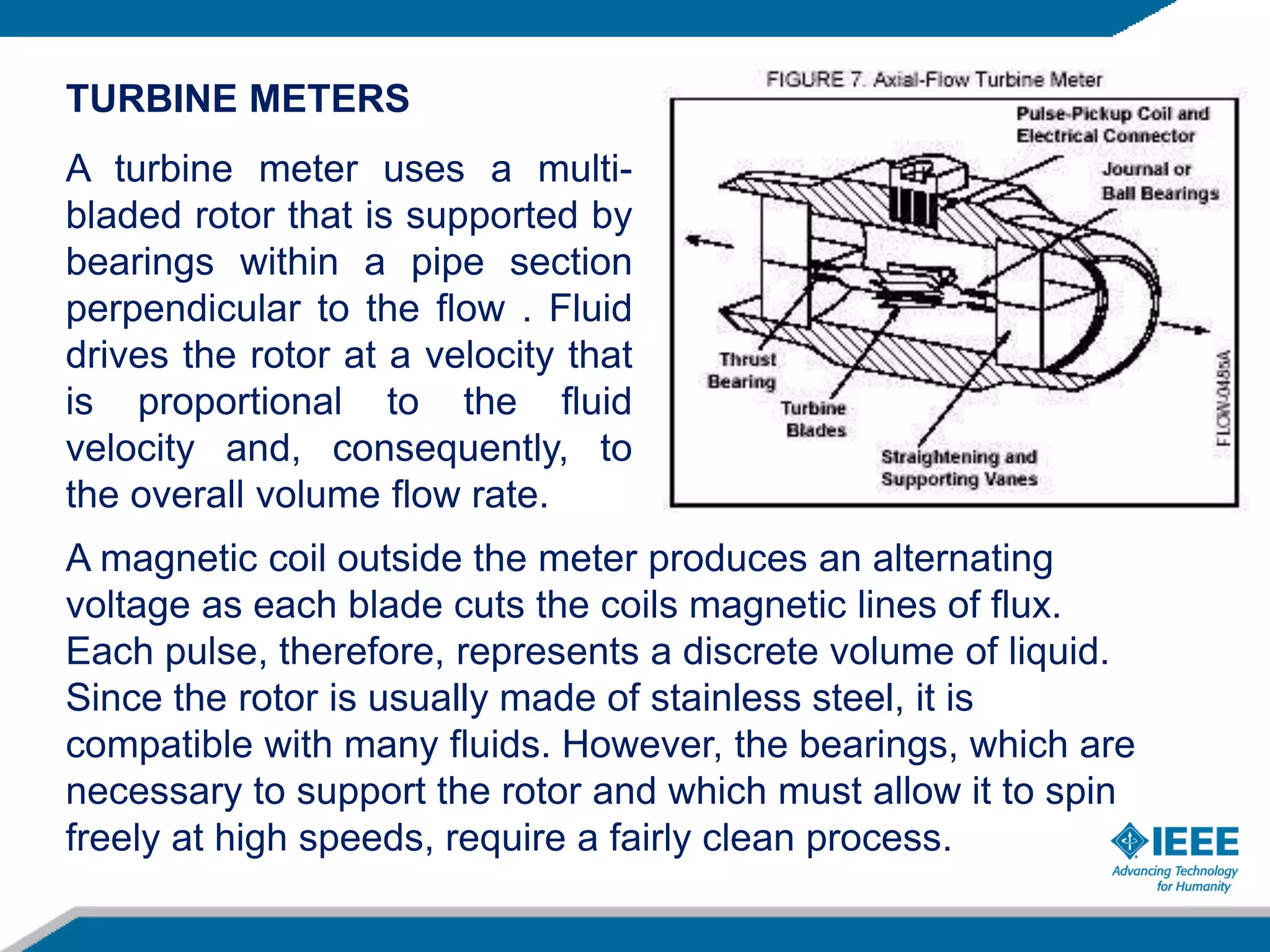
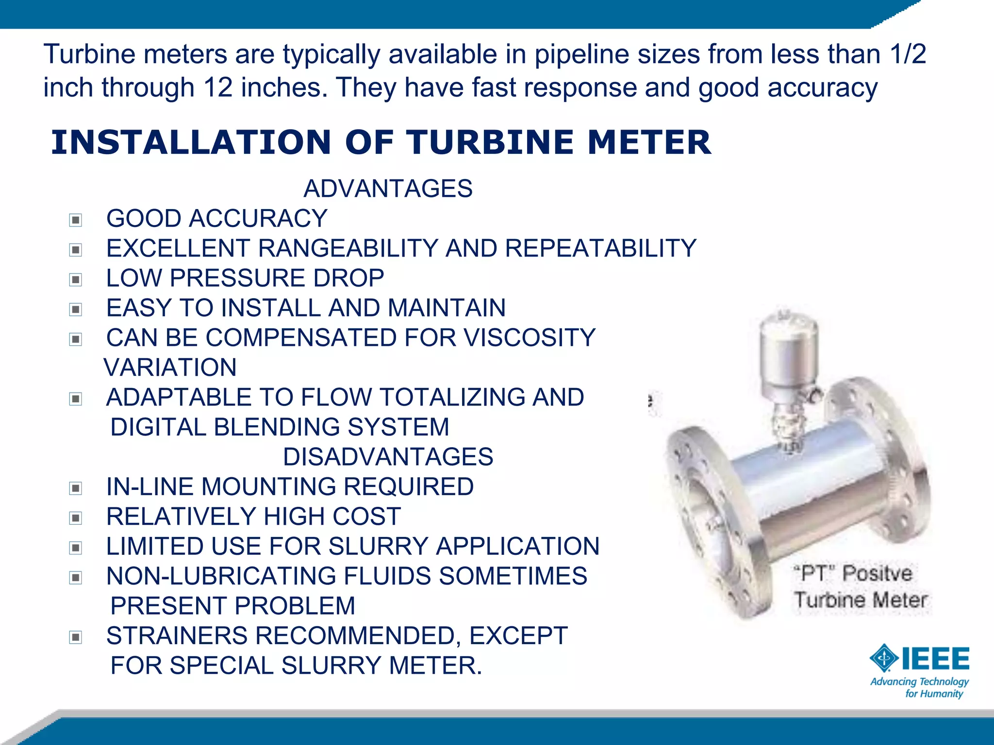
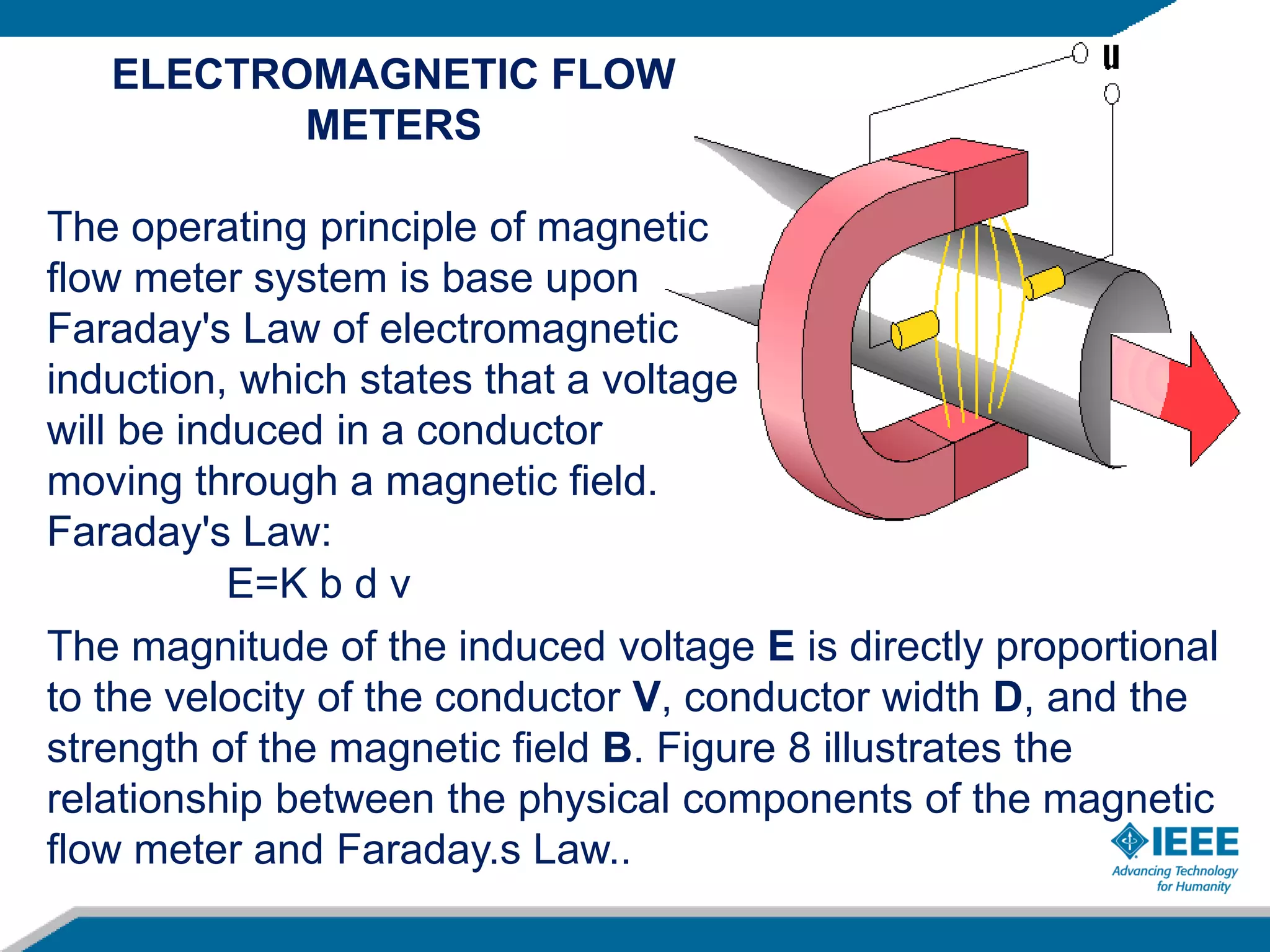
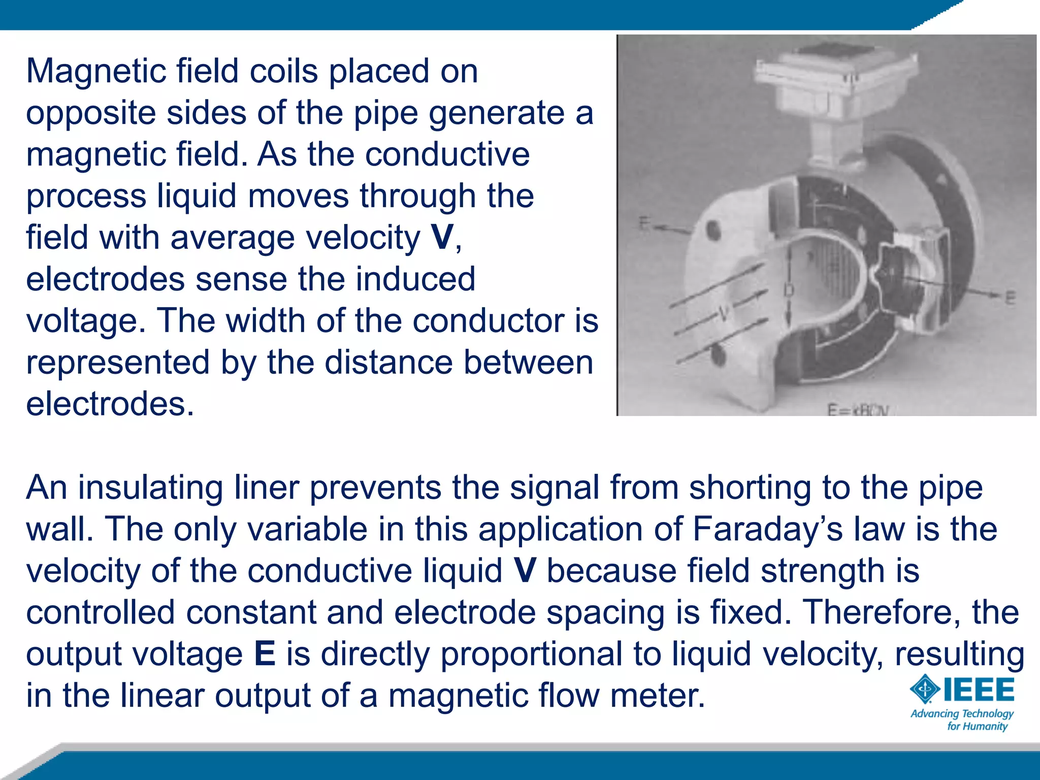
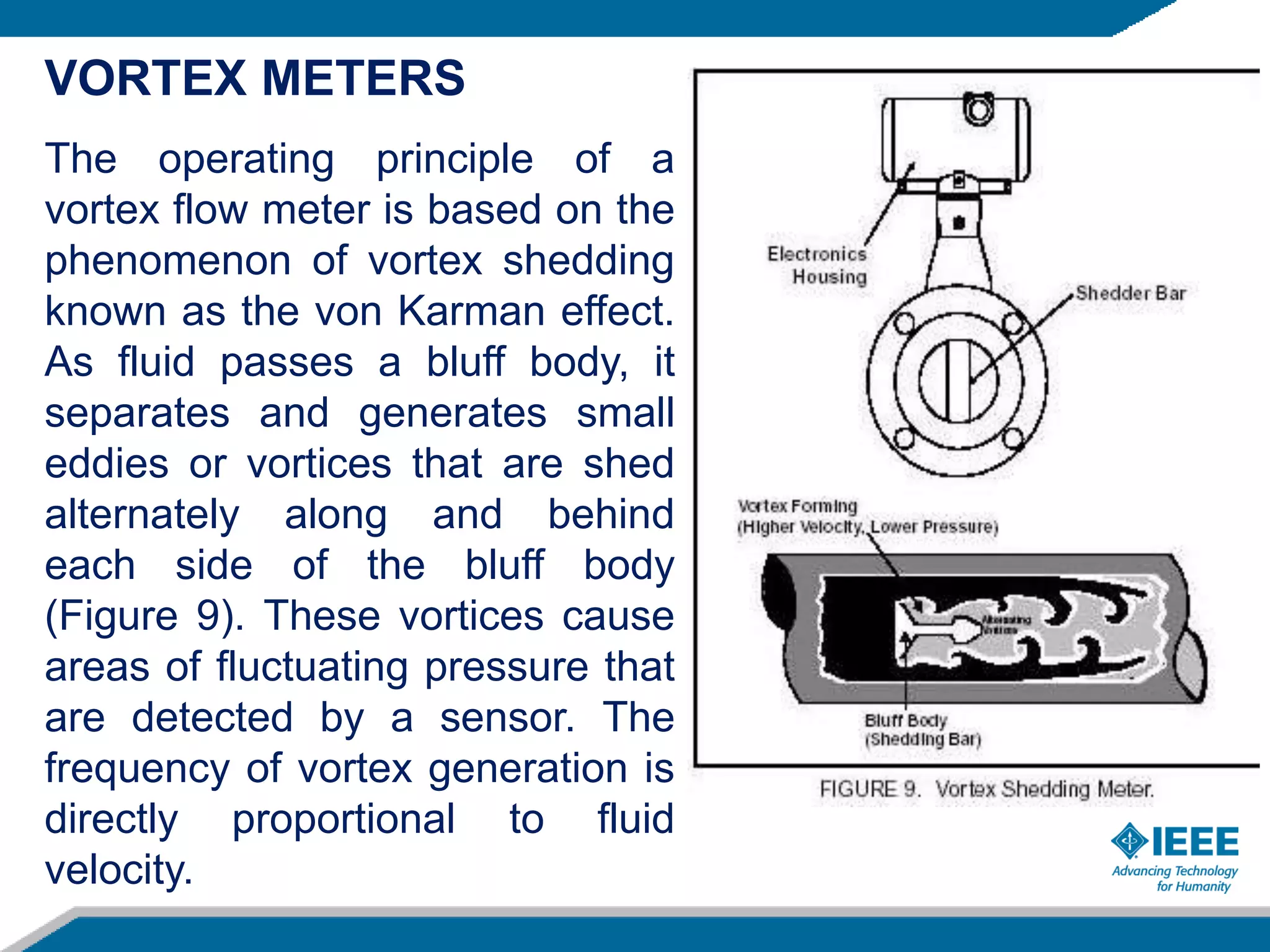
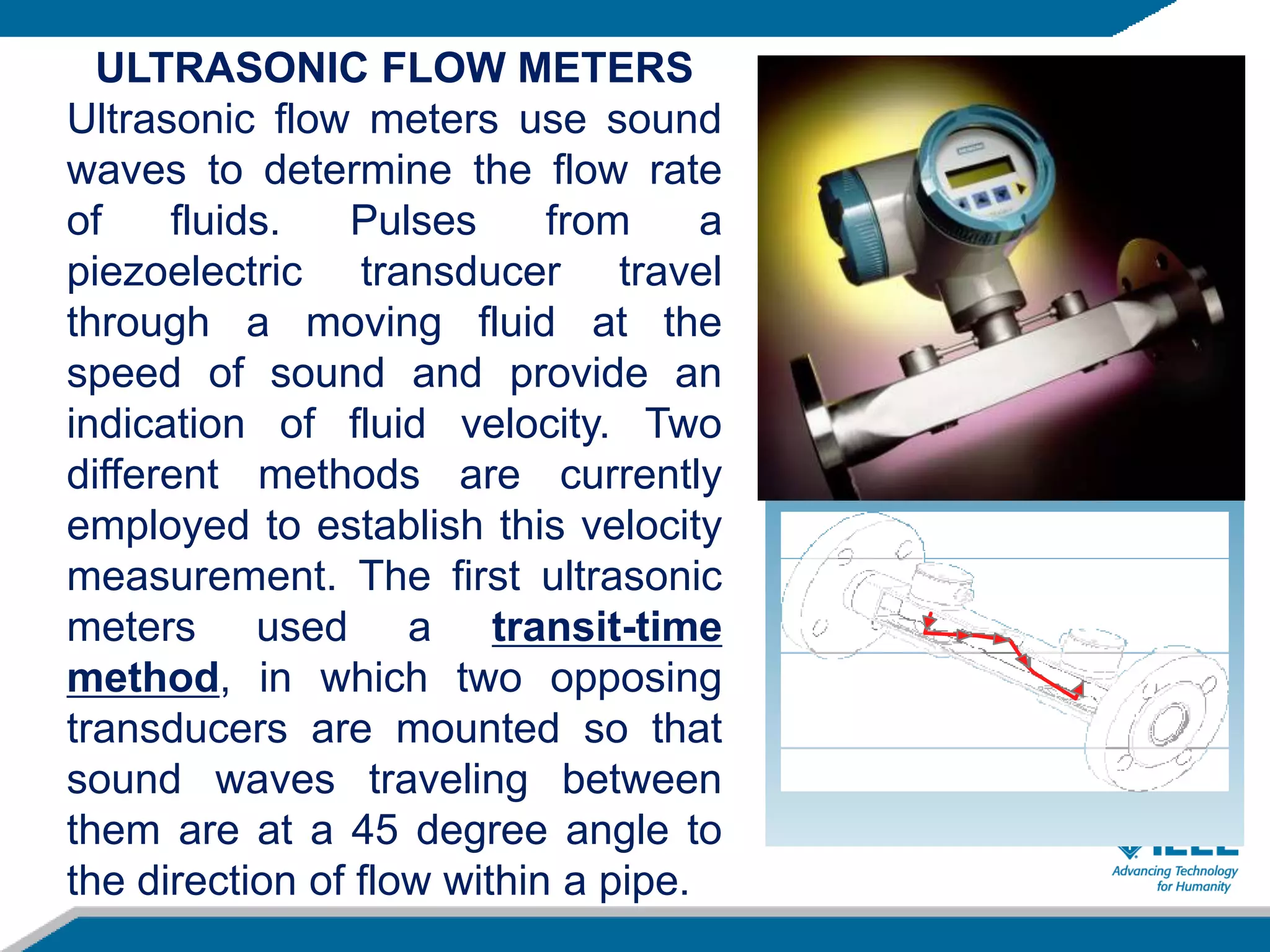


This document provides an overview of field instrumentation used for measurement, monitoring, and control. It discusses common process variables like flow, pressure, temperature, and level. It then focuses on different types of flow measurement instrumentation including positive displacement meters, head meters, velocity meters, and mass meters. Specific flow meter types are described in detail like orifice plates, venturi tubes, rotameters, turbine meters, electromagnetic flow meters, vortex meters, and ultrasonic flow meters. Advantages and disadvantages of each type are presented.