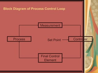
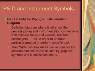
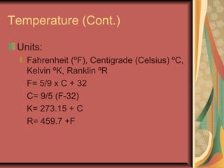
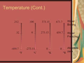
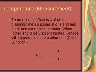
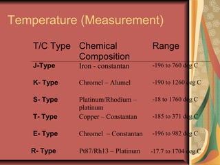
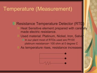
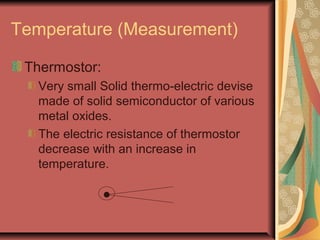
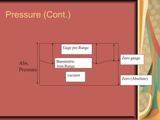
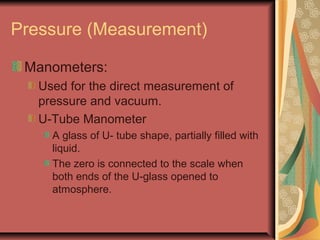
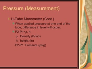
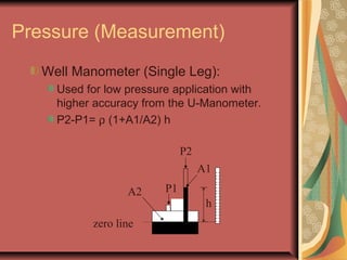
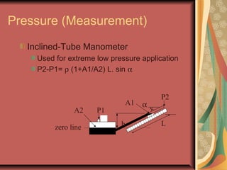
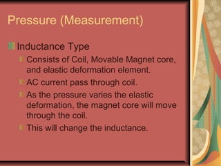
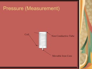
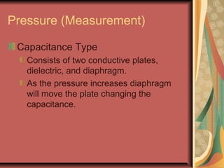
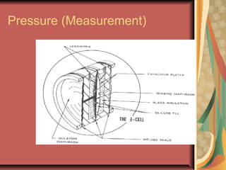
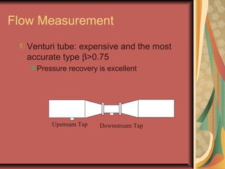
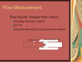
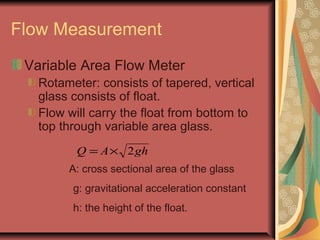
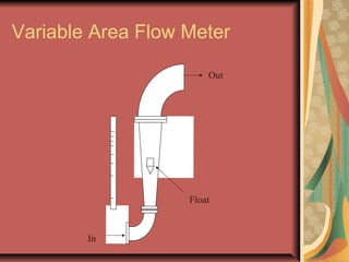
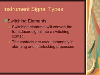
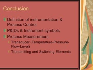
Basic Instrumentation
By: Md.Saquib Ansar Malick
Arabian Petrochemical Company
( Petrokemya)
SABIC
Contents
Definition of instrumentation &
Process Control
P&IDs & Instrument symbols
Process Measurement
Transducer (Temperature-Pressure-
Flow-Level)
Transmitting and Switching Elements
Definition of Instrumentation & Process Control
System
Instrumentation:
A collection of instruments for the purpose of
observation, measurement, protection or
control.
Process Control
Regulation or manipulation of variable
influencing the process to achieve desire
quantity/quality in an efficient manner
Block Diagram of Process Control Loop
Measurement
Controller
Final Control
Element
Process Set Point
P&ID and Instrument Symbols
P&ID stands for Piping & Instrumentation
Diagram
Definition:diagram where it will show the
process piping and instrumentation connections
with Process tanks and vessels, reactors,
exchangers, …etc. in order to produce
particular product or perform specific task.
The P&IDs contains detail connections for the
instrumentations where defined by graphical
symbols and identification letters.
Instrumentation Identification
Example of instrument Identification
FIC4003 (Flow indication and Control)
FI4002 (Flow Indication)
FT4003 (Flow Transmitter)
FV4003 (Flow Control Valve)
PIC4002 (Pressure Indication and
Control)
PV4002 (Pressure Control Valve)
PDSL1234 (Pressure Differential Switch
Low)
Control Loops
FT-1
FV-1
FIC
1
SV
PV
MV
FE-1
FY
1
Vent
AFC
FSL
1
IA
i
Process Measurement
In this lecture we will cover the
measurement instruments:
Temperature Elements
Pressure Elements
Flow Elements
Level Elements
I. Temperature
Definition:
It is the Degree of Coldness or hotness
or in other word related to the kinetic
energy of molecules.
Temperature generated by heat energy.
Heat energy has unit of BTU (Brithish
Thermal Unit) or Calorie
Temperature (Cont.)
Units:
Fahrenheit (ºF), Centigrade (Celsius) ºC,
Kelvin ºK, Ranklin ºR
F= 5/9 x C + 32
C= 9/5 (F-32)
K= 273.15 + C
R= 459.7 +F
Temperature (Cont.)
ºF ºC ºK ºR
-459.7
32
212
-273.15
0
100
0
273.15
373.15
0
459.7
671.7
Water
Freezing
Water
Boiling
Absolute
zero
Temperature (Measurement)
Thermocouple: Consists of two
dissimilar metals joined at one end and
other end connected to meter. When
joined end (Hot junction) heated, voltage
will be produced at the other end (Cold
Junction).
Temperature (Measurement)
T/C Type Chemical
Composition
Range
J-Type Iron - constantan -196 to 760 deg C
K- Type Chromel – Alumel -190 to 1260 deg C
S- Type Platinum/Rhodium –
platinum
-18 to 1760 deg C
T- Type Copper – Constantan -185 to 371 deg C
E- Type Chromel – Constantan -196 to 982 deg C
R- Type Pt87/Rh13 – Platinum -17.7 to 1704 deg C
Temperature (Measurement)
Resistance Temperature Detector (RTD)
Heat Sensitive element prepared with carefully
made electric resistance.
Used material: Platinum, Nickel, Iron, Salver
In our plant most of RTDs used are Pt100
platinum resistance= 100 ohm at 0 degree C
As temperature rises, resistance increases.
Temperature (Measurement)
Thermostor:
Very small Solid thermo-electric devise
made of solid semiconductor of various
metal oxides.
The electric resistance of thermostor
decrease with an increase in
temperature.
II. Pressure
Definition:
Defined as the normal force per unit
area acting on surface of an object.
P=F/A
Units:
Pa, psi, inches of mercury, inches of
water, BAR, atm, Kg/cm2
Pressure (Cont.)
Scale of measurement:
Gauge Pressure Scale
Absolute Pressure Scale
Vacuum Pressure Scale
Pg= Pa - Atmospheric Pressure
Pressure (Cont.)
vacuum
Gage pre.Range
Barometric
Atm.Range
Zero gauge
Zero (Absolute)
Abs.
Pressure
Pressure (Measurement)
Manometers:
Used for the direct measurement of
pressure and vacuum.
U-Tube Manometer
A glass of U- tube shape, partially filled with
liquid.
The zero is connected to the scale when
both ends of the U-glass opened to
atmosphere.
P1 P2
h
U-Tube Manometer
Pressure (Measurement)
U-Tube Manometer (Cont.)
When applied pressure at one end of the
tube, difference in level will occur:
P2-P1=ρ. h
ρ : Density (lb/in3)
h : height (in)
P2-P1: Pressure (psig)
Pressure (Measurement)
Well Manometer (Single Leg):
Used for low pressure application with
higher accuracy from the U-Manometer.
P2-P1= ρ (1+A1/A2) h
P1
P2
h
zero line
A2
A1
Pressure (Measurement)
Inclined-Tube Manometer
Used for extreme low pressure application
P2-P1= ρ (1+A1/A2) L. sin α
P1
P2
zero line
A2
A1
h L
α
Pressure (Measurement)
Pressure Element
Mechanical devices changed its shape
when pressure is applied
The pressure elements sometimes
called elastic deformation pressure
element
Each type has its range of operation
pressure.
Pressure (Measurement)
Pressure elements Minimum range Maximum range
i)Diaphragm 0”to 2” water column (WC) 0 to 400 psi
ii).Bellows 0”to 5” water column (WC) 0 to 800 psi
iii)Capsule 0”to 1” water column (WC) 0 to 50psi
iv)Bourdon tube 0 to 12 psi 0 to 100,000 psi
v)Spiral 0 to 115 psi 0 to 4,000 psi
vi)Helix 0 to 50 psi 0 to 10,000psi
Pressure (Measurement)
Pressure Transducers
Elastic deformation element joined to
electrical device.
Changes in resistance, inductance, or
capacitance
Pressure (Measurement)
Strain Gauge:
Fine wire in form of grid.
When the grid distorted, resistance of
the wire will change according to:
R=K. L/A
K : Resistively of the metal
L : Length of wire
A : Cross sectional Area
Pressure (Measurement)
Grid Wire
Ceramic or
paper backing
Lead
wires
Strain Gage
Pressure (Measurement)
Strain Gage (Cont.)
As Strain Gage is distorted by the elastic
deformation length will increase and area
will reduced.
Resistance will increase accordingly.
Pressure (Measurement)
Inductance Type
Consists of Coil, Movable Magnet core,
and elastic deformation element.
AC current pass through coil.
As the pressure varies the elastic
deformation, the magnet core will move
through the coil.
This will change the inductance.
Pressure (Measurement)
Movable Iron Core
Coil
Non Conductive Tube
Capacitance Type
Consists of two conductive plates,
dielectric, and diaphragm.
As the pressure increases diaphragm
will move the plate changing the
capacitance.
Pressure (Measurement)
Flow (Measurement)
Flow rate and flow quantity of materials
is made primarily for determining the
proportions of materials introduced to
the process.
Method of measurements:
Head Elements
Area Elements
Quantity Velocity Elements
Flow (Measurement)
The following properties are important
for the flow measurement:
Pressure: Force applied on Area
Density : Weight divided by volume
Viscosity : Resistance to flow
Velocity : Speed of the fluid. It determine
the behavior of the fluid.
Flow (Measurement)
Flow Types:
When the average velocity is slow, the
flow is called laminar, i.e fastest layers at
the center and the slowest at the edges
When the average velocity increases,
the flow is called turbulent.
The measurement of laminar, turbulent
flow is as per Reynolds number
Flow (Measurement)
Laminar Flow
Turbulent Flow
Flow (Measurement)
Most Flow are design to work in
turbulent flow
Units of Flow:
lb/Hr, Kg/Hr, T/Hr: mass flow
cfm, M3/H, KNM3/Hr: Volumetric Flow
Flow Measurement
Head Flow Elements
When the liquid flows through a
restriction, the energy converted kinetic
energy.
The pressure will drop and velocity
increases.
PCQ ∆×=
C: constant
∆P: Differential pressure across restriction
Flow Measurement
Head Flow Elements
Orifice Plate: the loss in the pressure is
more that other type of flow
measurement.
The selection of orifice plate based on ratio
of bore diameter to (d) to inside pipe
diameter (D). β= d/D
best accuracy is when: 0.2 < β < 0.6
Taps used :
– Flange tap
– Pipe taps
– Vena Contracta tap
Flow Measurement
Venturi tube: expensive and the most
accurate type β>0.75
Pressure recovery is excellent
Upstream Tap Downstream Tap
Flow Measurement
Flow Nozzle: cheaper than venturi,
accuracy less than venturi
β>0.75
pressure recovery is not as good as venturi
Upstream Tap Downstream Tap
Flow Measurement
Variable Area Flow Meter
Rotameter: consists of tapered, vertical
glass consists of float.
Flow will carry the float from bottom to
top through variable area glass.
ghAQ 2×=
A: cross sectional area of the glass
g: gravitational acceleration constant
h: the height of the float.
Variable Area Flow Meter
In
Out
Float
Flow Measurement
Quantity Flow Measurement
Positive displacement
Measure the total quantity of the flow
separate the liquid into discrete volumes
Total of these volumes in time period will
give the total flow amount
Mass Flow meter:
measurement of the weight per unit time.
Continuous measurement of density
Level
There is two ways of measuring level
Direct level measurement
by varying liquid will get the level
Indirect level measurement
by using a variables which changes with the
liquid level changes.
Level Measurement
Float
special material designed to follow the
level or the interface level of a tank
The specialty is the density of the float
shall be always touching the desired
measurement level.
As the level increases/decreases, float
will follow and causing a connecting tape
to change its length.
Level Measurement
Displacer
Archimede’s Principle: a body wholly or partially
immersed in a fluid is buoyed up by a force
equal to the weight of the fluid displaced.
The level is measured by detecting the
buoyancy force of an immersed displacer
The major difference between float and
displacer is that displacer is partially or totally
immersed, while float is always floating in the
surface of the level.
Displacer
Flexible Cable
Float
Level Measurement
Differential pressure
h = ∆P/ρ (British unit) inches
h= ∆P/(g.ρ) (SI unit) meters
as level changes differential pressure will
change accordingly.
L
T
Instrument Signal Types
All measurement elements are sent to
DCS/ESD/PLC Either for alarming,
interlocking or controlling.
Measurement Instrumentation consists
of two parts
Measurement elements (Transducer)-
Covered in the previous sections
Transmitting elements
Switching elements
Instrument Signal Types
Transmitting Elements
Transmitting element will convert the
Transducer signals into either electronic or
pneumatic signals
Transmitting elements are commonly used for
indication and control
Electronic transmitter will send 4 ~ 20 mA
4mA : min. range
20mA: max. range
Pneumatic transmitter will convert the
transducer signal into 3~15 psi
3 psi = min. range
15 psi = max range
Instrument Signal Types
Switching Elements
Switching elements will convert the
transducer signal into a switching
contact
The contacts are used commonly in
alarming and interlocking processes
Conclusion
Definition of instrumentation &
Process Control
P&IDs & Instrument symbols
Process Measurement
Transducer (Temperature-Pressure-
Flow-Level)
Transmitting and Switching Elements
??QUESTIONS??
THANK YOU

107 basic instrumentation

  • 1.
    Basic Instrumentation By: Md.SaquibAnsar Malick Arabian Petrochemical Company ( Petrokemya) SABIC
  • 2.
    Contents Definition of instrumentation& Process Control P&IDs & Instrument symbols Process Measurement Transducer (Temperature-Pressure- Flow-Level) Transmitting and Switching Elements
  • 3.
    Definition of Instrumentation& Process Control System Instrumentation: A collection of instruments for the purpose of observation, measurement, protection or control. Process Control Regulation or manipulation of variable influencing the process to achieve desire quantity/quality in an efficient manner
  • 4.
    Block Diagram ofProcess Control Loop Measurement Controller Final Control Element Process Set Point
  • 5.
    P&ID and InstrumentSymbols P&ID stands for Piping & Instrumentation Diagram Definition:diagram where it will show the process piping and instrumentation connections with Process tanks and vessels, reactors, exchangers, …etc. in order to produce particular product or perform specific task. The P&IDs contains detail connections for the instrumentations where defined by graphical symbols and identification letters.
  • 8.
    Instrumentation Identification Example ofinstrument Identification FIC4003 (Flow indication and Control) FI4002 (Flow Indication) FT4003 (Flow Transmitter) FV4003 (Flow Control Valve) PIC4002 (Pressure Indication and Control) PV4002 (Pressure Control Valve) PDSL1234 (Pressure Differential Switch Low)
  • 9.
  • 10.
    Process Measurement In thislecture we will cover the measurement instruments: Temperature Elements Pressure Elements Flow Elements Level Elements
  • 11.
    I. Temperature Definition: It isthe Degree of Coldness or hotness or in other word related to the kinetic energy of molecules. Temperature generated by heat energy. Heat energy has unit of BTU (Brithish Thermal Unit) or Calorie
  • 12.
    Temperature (Cont.) Units: Fahrenheit (ºF),Centigrade (Celsius) ºC, Kelvin ºK, Ranklin ºR F= 5/9 x C + 32 C= 9/5 (F-32) K= 273.15 + C R= 459.7 +F
  • 13.
    Temperature (Cont.) ºF ºCºK ºR -459.7 32 212 -273.15 0 100 0 273.15 373.15 0 459.7 671.7 Water Freezing Water Boiling Absolute zero
  • 14.
    Temperature (Measurement) Thermocouple: Consistsof two dissimilar metals joined at one end and other end connected to meter. When joined end (Hot junction) heated, voltage will be produced at the other end (Cold Junction).
  • 15.
    Temperature (Measurement) T/C TypeChemical Composition Range J-Type Iron - constantan -196 to 760 deg C K- Type Chromel – Alumel -190 to 1260 deg C S- Type Platinum/Rhodium – platinum -18 to 1760 deg C T- Type Copper – Constantan -185 to 371 deg C E- Type Chromel – Constantan -196 to 982 deg C R- Type Pt87/Rh13 – Platinum -17.7 to 1704 deg C
  • 16.
    Temperature (Measurement) Resistance TemperatureDetector (RTD) Heat Sensitive element prepared with carefully made electric resistance. Used material: Platinum, Nickel, Iron, Salver In our plant most of RTDs used are Pt100 platinum resistance= 100 ohm at 0 degree C As temperature rises, resistance increases.
  • 17.
    Temperature (Measurement) Thermostor: Very smallSolid thermo-electric devise made of solid semiconductor of various metal oxides. The electric resistance of thermostor decrease with an increase in temperature.
  • 18.
    II. Pressure Definition: Defined asthe normal force per unit area acting on surface of an object. P=F/A Units: Pa, psi, inches of mercury, inches of water, BAR, atm, Kg/cm2
  • 19.
    Pressure (Cont.) Scale ofmeasurement: Gauge Pressure Scale Absolute Pressure Scale Vacuum Pressure Scale Pg= Pa - Atmospheric Pressure
  • 20.
  • 21.
    Pressure (Measurement) Manometers: Used forthe direct measurement of pressure and vacuum. U-Tube Manometer A glass of U- tube shape, partially filled with liquid. The zero is connected to the scale when both ends of the U-glass opened to atmosphere.
  • 22.
  • 23.
    Pressure (Measurement) U-Tube Manometer(Cont.) When applied pressure at one end of the tube, difference in level will occur: P2-P1=ρ. h ρ : Density (lb/in3) h : height (in) P2-P1: Pressure (psig)
  • 24.
    Pressure (Measurement) Well Manometer(Single Leg): Used for low pressure application with higher accuracy from the U-Manometer. P2-P1= ρ (1+A1/A2) h P1 P2 h zero line A2 A1
  • 25.
    Pressure (Measurement) Inclined-Tube Manometer Usedfor extreme low pressure application P2-P1= ρ (1+A1/A2) L. sin α P1 P2 zero line A2 A1 h L α
  • 26.
    Pressure (Measurement) Pressure Element Mechanicaldevices changed its shape when pressure is applied The pressure elements sometimes called elastic deformation pressure element Each type has its range of operation pressure.
  • 27.
    Pressure (Measurement) Pressure elementsMinimum range Maximum range i)Diaphragm 0”to 2” water column (WC) 0 to 400 psi ii).Bellows 0”to 5” water column (WC) 0 to 800 psi iii)Capsule 0”to 1” water column (WC) 0 to 50psi iv)Bourdon tube 0 to 12 psi 0 to 100,000 psi v)Spiral 0 to 115 psi 0 to 4,000 psi vi)Helix 0 to 50 psi 0 to 10,000psi
  • 28.
    Pressure (Measurement) Pressure Transducers Elasticdeformation element joined to electrical device. Changes in resistance, inductance, or capacitance
  • 29.
    Pressure (Measurement) Strain Gauge: Finewire in form of grid. When the grid distorted, resistance of the wire will change according to: R=K. L/A K : Resistively of the metal L : Length of wire A : Cross sectional Area
  • 30.
    Pressure (Measurement) Grid Wire Ceramicor paper backing Lead wires Strain Gage
  • 31.
    Pressure (Measurement) Strain Gage(Cont.) As Strain Gage is distorted by the elastic deformation length will increase and area will reduced. Resistance will increase accordingly.
  • 33.
    Pressure (Measurement) Inductance Type Consistsof Coil, Movable Magnet core, and elastic deformation element. AC current pass through coil. As the pressure varies the elastic deformation, the magnet core will move through the coil. This will change the inductance.
  • 34.
    Pressure (Measurement) Movable IronCore Coil Non Conductive Tube
  • 35.
    Capacitance Type Consists oftwo conductive plates, dielectric, and diaphragm. As the pressure increases diaphragm will move the plate changing the capacitance. Pressure (Measurement)
  • 36.
  • 37.
    Flow (Measurement) Flow rateand flow quantity of materials is made primarily for determining the proportions of materials introduced to the process. Method of measurements: Head Elements Area Elements Quantity Velocity Elements
  • 38.
    Flow (Measurement) The followingproperties are important for the flow measurement: Pressure: Force applied on Area Density : Weight divided by volume Viscosity : Resistance to flow Velocity : Speed of the fluid. It determine the behavior of the fluid.
  • 39.
    Flow (Measurement) Flow Types: Whenthe average velocity is slow, the flow is called laminar, i.e fastest layers at the center and the slowest at the edges When the average velocity increases, the flow is called turbulent. The measurement of laminar, turbulent flow is as per Reynolds number
  • 40.
  • 41.
    Flow (Measurement) Most Floware design to work in turbulent flow Units of Flow: lb/Hr, Kg/Hr, T/Hr: mass flow cfm, M3/H, KNM3/Hr: Volumetric Flow
  • 42.
    Flow Measurement Head FlowElements When the liquid flows through a restriction, the energy converted kinetic energy. The pressure will drop and velocity increases. PCQ ∆×= C: constant ∆P: Differential pressure across restriction
  • 43.
    Flow Measurement Head FlowElements Orifice Plate: the loss in the pressure is more that other type of flow measurement. The selection of orifice plate based on ratio of bore diameter to (d) to inside pipe diameter (D). β= d/D best accuracy is when: 0.2 < β < 0.6 Taps used : – Flange tap – Pipe taps – Vena Contracta tap
  • 45.
    Flow Measurement Venturi tube:expensive and the most accurate type β>0.75 Pressure recovery is excellent Upstream Tap Downstream Tap
  • 46.
    Flow Measurement Flow Nozzle:cheaper than venturi, accuracy less than venturi β>0.75 pressure recovery is not as good as venturi Upstream Tap Downstream Tap
  • 47.
    Flow Measurement Variable AreaFlow Meter Rotameter: consists of tapered, vertical glass consists of float. Flow will carry the float from bottom to top through variable area glass. ghAQ 2×= A: cross sectional area of the glass g: gravitational acceleration constant h: the height of the float.
  • 48.
    Variable Area FlowMeter In Out Float
  • 49.
    Flow Measurement Quantity FlowMeasurement Positive displacement Measure the total quantity of the flow separate the liquid into discrete volumes Total of these volumes in time period will give the total flow amount Mass Flow meter: measurement of the weight per unit time. Continuous measurement of density
  • 50.
    Level There is twoways of measuring level Direct level measurement by varying liquid will get the level Indirect level measurement by using a variables which changes with the liquid level changes.
  • 51.
    Level Measurement Float special materialdesigned to follow the level or the interface level of a tank The specialty is the density of the float shall be always touching the desired measurement level. As the level increases/decreases, float will follow and causing a connecting tape to change its length.
  • 52.
    Level Measurement Displacer Archimede’s Principle:a body wholly or partially immersed in a fluid is buoyed up by a force equal to the weight of the fluid displaced. The level is measured by detecting the buoyancy force of an immersed displacer The major difference between float and displacer is that displacer is partially or totally immersed, while float is always floating in the surface of the level.
  • 53.
  • 54.
    Level Measurement Differential pressure h= ∆P/ρ (British unit) inches h= ∆P/(g.ρ) (SI unit) meters as level changes differential pressure will change accordingly. L T
  • 55.
    Instrument Signal Types Allmeasurement elements are sent to DCS/ESD/PLC Either for alarming, interlocking or controlling. Measurement Instrumentation consists of two parts Measurement elements (Transducer)- Covered in the previous sections Transmitting elements Switching elements
  • 56.
    Instrument Signal Types TransmittingElements Transmitting element will convert the Transducer signals into either electronic or pneumatic signals Transmitting elements are commonly used for indication and control Electronic transmitter will send 4 ~ 20 mA 4mA : min. range 20mA: max. range Pneumatic transmitter will convert the transducer signal into 3~15 psi 3 psi = min. range 15 psi = max range
  • 57.
    Instrument Signal Types SwitchingElements Switching elements will convert the transducer signal into a switching contact The contacts are used commonly in alarming and interlocking processes
  • 58.
    Conclusion Definition of instrumentation& Process Control P&IDs & Instrument symbols Process Measurement Transducer (Temperature-Pressure- Flow-Level) Transmitting and Switching Elements
  • 59.
  • 60.