Downloaded 2,029 times


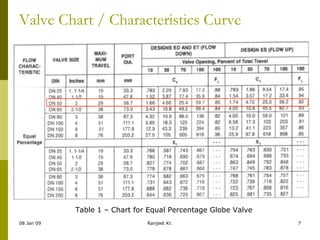
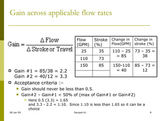

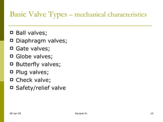
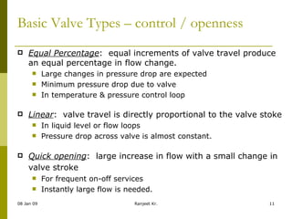


The document outlines the process of valve sizing and selection, highlighting key steps such as initial calculations of pressure drops and valve characteristics (C v). It details various valve types, their operating characteristics, advantages, and disadvantages, emphasizing the importance of proper selection based on application needs. Key considerations include maintaining valve stroke percentages and understanding flow characteristics to ensure efficient system performance.


