

![Digital systems principles and applications
oBy Tocci 2001
Synthesis And Optimization of Digital
circuits
o Giovani De Micheli
Digital Logic Design [Sequential circuits]
oDr. Eng. Ahmed H. Madian
http://en.wikipedia.org/wiki/Moore_machine
http://en.wikipedia.org/wiki/Mealy_machine
04/21/15 30](https://image.slidesharecdn.com/sequentiallogicoptimization-150421075320-conversion-gate01/85/Sequential-logic-circuit-optimization-30-320.jpg)


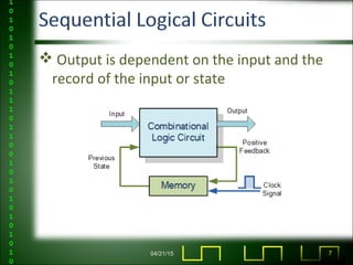
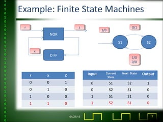
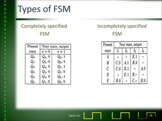
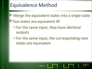
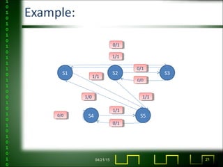
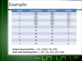
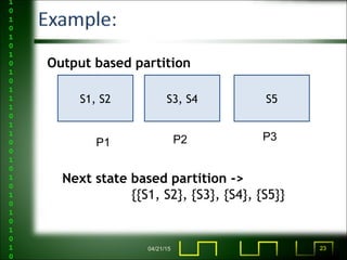
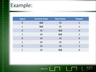
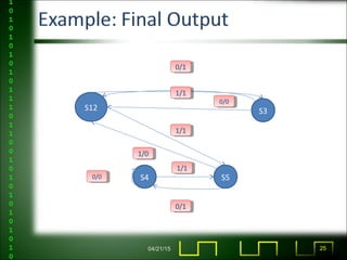
The document discusses sequential logic circuits and finite state machines. It covers topics like combinational vs sequential logic, what defines a finite state machine, state transition diagrams, equivalent state partitioning for minimization, and applications like computer memory and delay elements. Examples are provided of a sequential circuit and its state table, as well as the process of state minimization.