Faculty Orientation Workshop
on
SE(E&TC)Revised Syllabus_2024 Course
Digital Electronics
Unit 3: State Machines
under the aegis of
Board of Studies E&TC, SPPU, Pune.
[09/07/2025]
By- Dr. Nilima R. Dhumale
SCOE, Pune 1
Contents (08Hours)
Moore andMealy machines
State diagram, State table, State reduction, State assignment
Finite state machine implementation
Sequence detector
Introduction to Algorithmic state machines- construction of ASM chart and
realization for sequential circuits
Assignments / Case Study 12 Marks Units 3 & Unit 4 (6 Marks/Unit)
3
4.
Combinational and SequentialCircuit
• Combinational circuits can be completely described by the truth table.
• Sequential systems contain state stored in memory elements internal to the
system. Their behavior depends both on the set of inputs supplied and on the
contents of the internal memory, or state of the system. Thus, a sequential
system cannot be described with a truth table.
• Sequential system is described as a finite-state machine (or often just state
machine).
4
5.
Finite State Machine(FSM)
• A Finite State Machine (FSM) in digital electronics is a computational model
used to design both computer programs and sequential logic circuits. It consists of
a finite number of states, transitions between those states, inputs, and outputs
.
• Key Components of an FSM:
States: Distinct modes or conditions in which the system can exist.
Inputs: External signals that affect transitions between states.
Transitions: Rules that define how the system moves from one state to another
based on inputs.
Outputs: Signals or actions that result from the current state (and possibly the
input).
5
6.
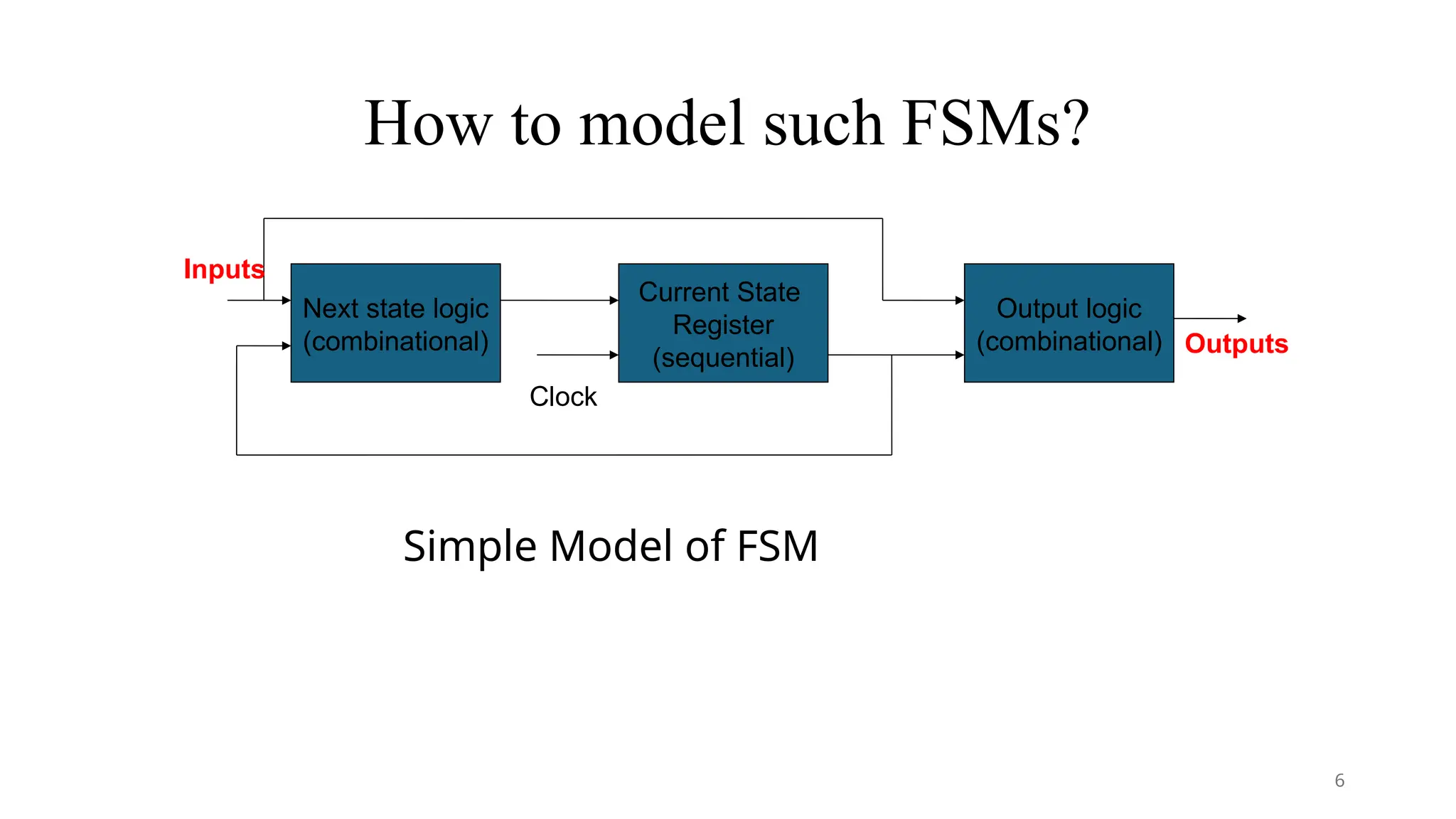
How to modelsuch FSMs?
Simple Model of FSM
Next state logic
(combinational)
Current State
Register
(sequential)
Output logic
(combinational)
Clock
Outputs
Inputs
6
7.
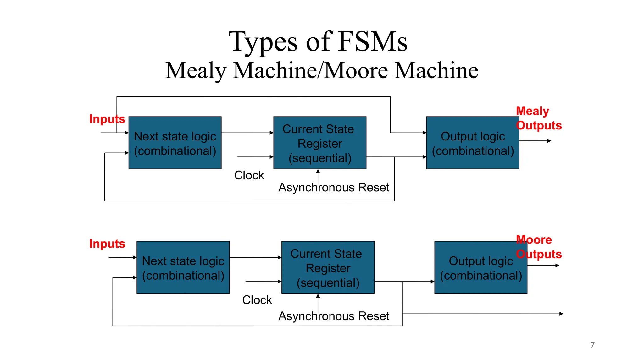
Types of FSMs
MealyMachine/Moore Machine
Next state logic
(combinational)
Current State
Register
(sequential)
Output logic
(combinational)
Clock
Mealy
Outputs
Inputs
Next state logic
(combinational)
Current State
Register
(sequential)
Output logic
(combinational)
Clock
Moore
Outputs
Inputs
Asynchronous Reset
Asynchronous Reset
7
8.
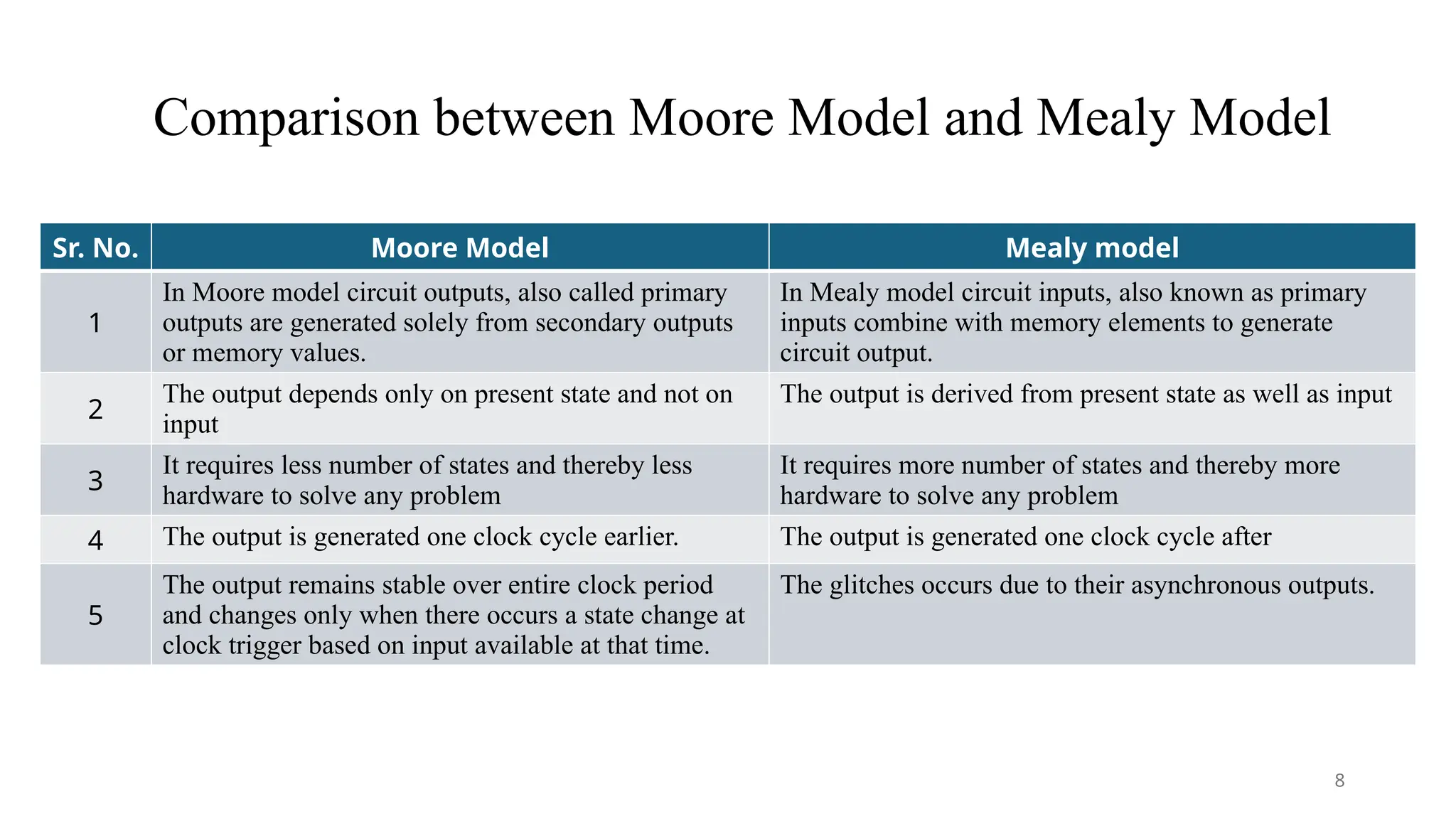
Comparison between MooreModel and Mealy Model
Sr. No. Moore Model Mealy model
1
In Moore model circuit outputs, also called primary
outputs are generated solely from secondary outputs
or memory values.
In Mealy model circuit inputs, also known as primary
inputs combine with memory elements to generate
circuit output.
2
The output depends only on present state and not on
input
The output is derived from present state as well as input
3
It requires less number of states and thereby less
hardware to solve any problem
It requires more number of states and thereby more
hardware to solve any problem
4 The output is generated one clock cycle earlier. The output is generated one clock cycle after
5
The output remains stable over entire clock period
and changes only when there occurs a state change at
clock trigger based on input available at that time.
The glitches occurs due to their asynchronous outputs.
8
9.
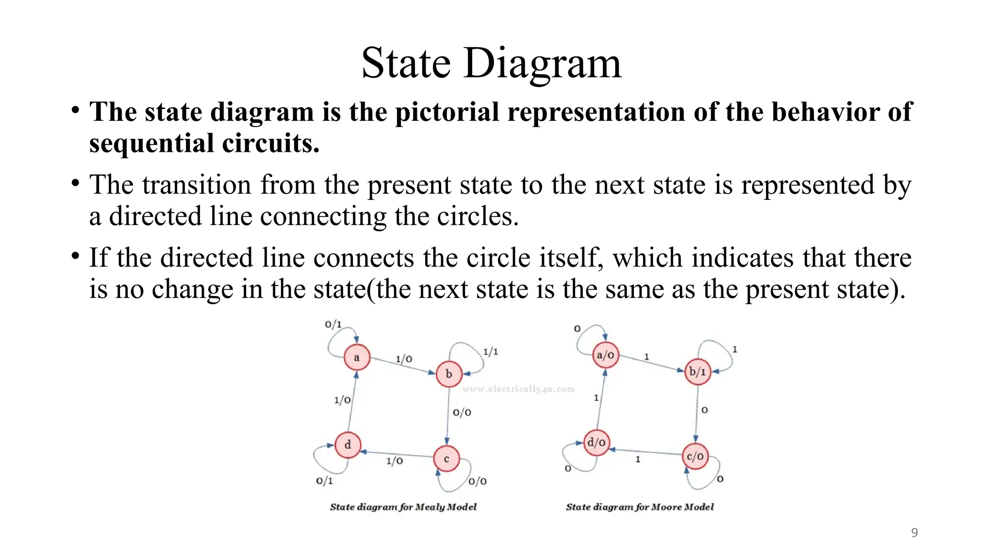
State Diagram
• Thestate diagram is the pictorial representation of the behavior of
sequential circuits.
• The transition from the present state to the next state is represented by
a directed line connecting the circles.
• If the directed line connects the circle itself, which indicates that there
is no change in the state(the next state is the same as the present state).
9
10.
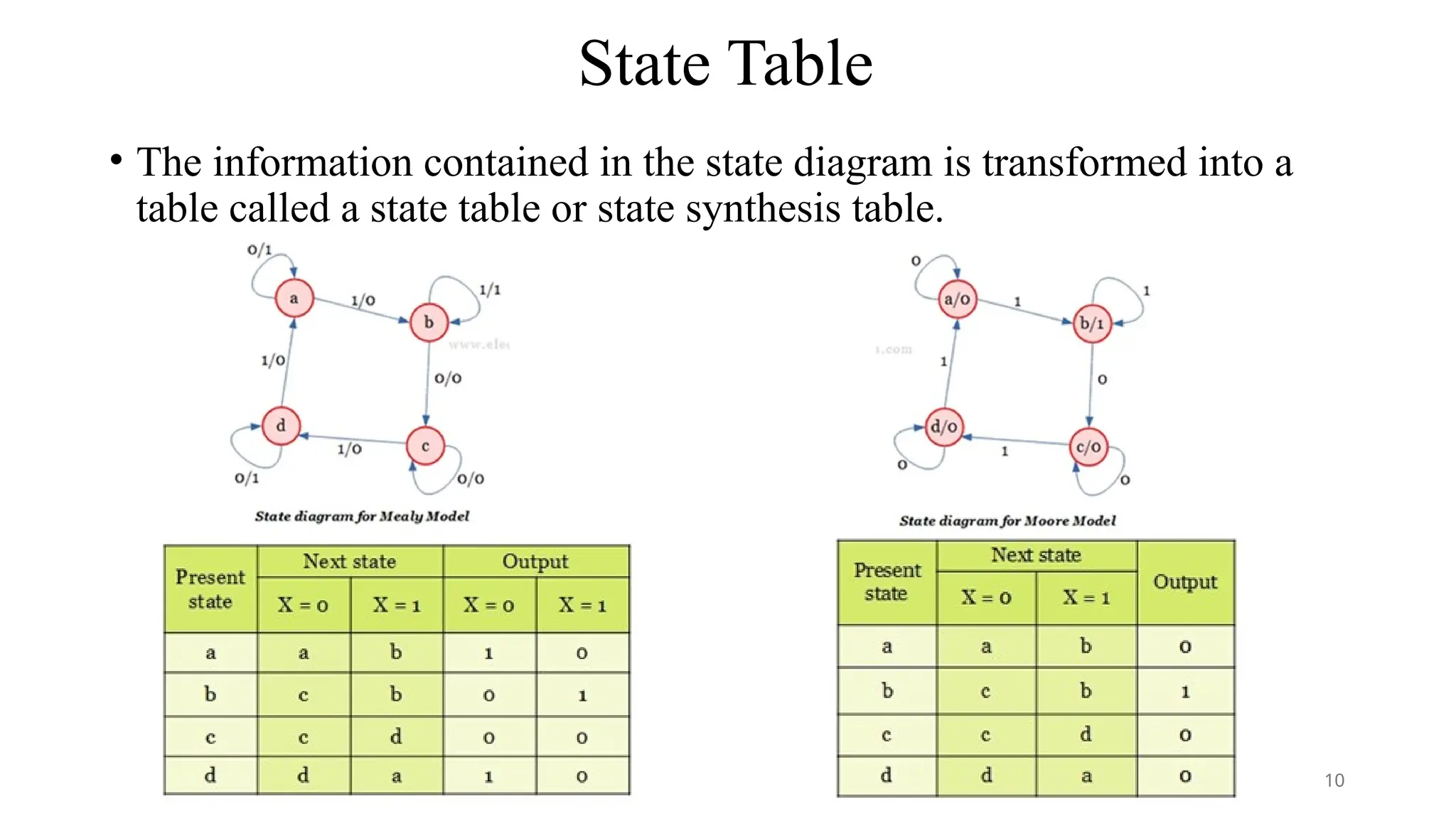
State Table
• Theinformation contained in the state diagram is transformed into a
table called a state table or state synthesis table.
10
11.
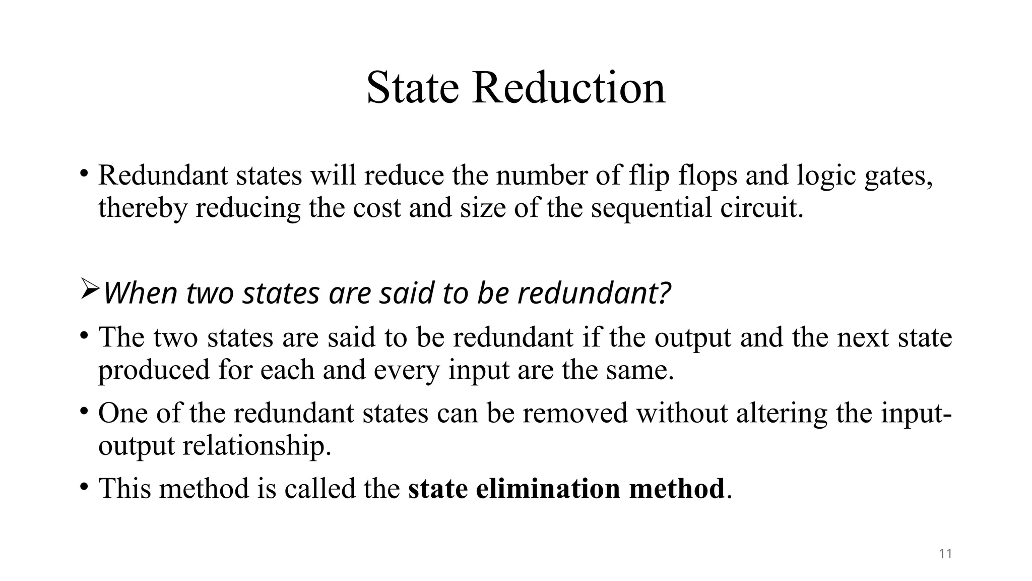
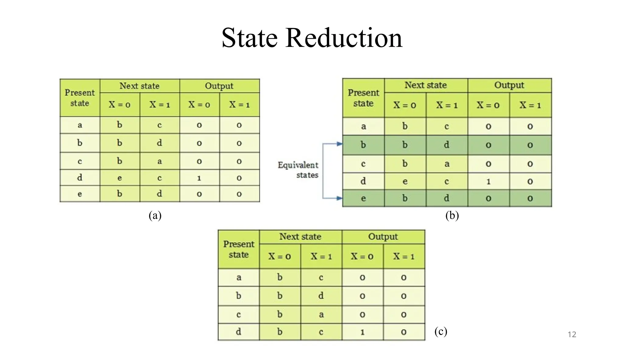
State Reduction
• Redundantstates will reduce the number of flip flops and logic gates,
thereby reducing the cost and size of the sequential circuit.
When two states are said to be redundant?
• The two states are said to be redundant if the output and the next state
produced for each and every input are the same.
• One of the redundant states can be removed without altering the input-
output relationship.
• This method is called the state elimination method.
11
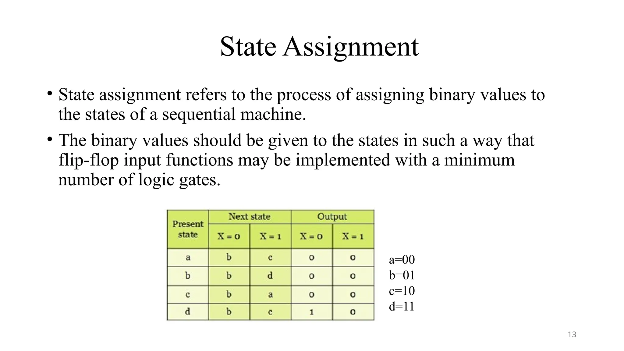
State Assignment
• Stateassignment refers to the process of assigning binary values to
the states of a sequential machine.
• The binary values should be given to the states in such a way that
flip-flop input functions may be implemented with a minimum
number of logic gates.
a=00
b=01
c=10
d=11
13
14.
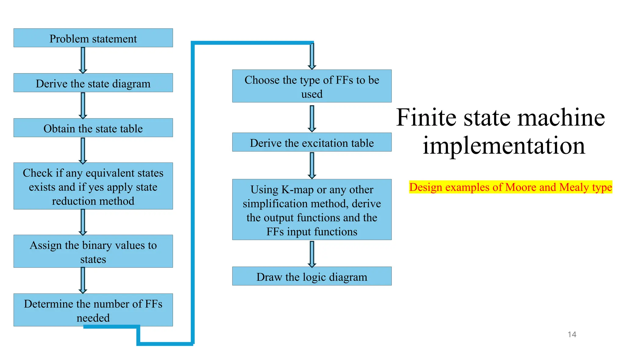
Finite state machine
implementation
Derivethe state diagram
Obtain the state table
Check if any equivalent states
exists and if yes apply state
reduction method
Assign the binary values to
states
Determine the number of FFs
needed
Choose the type of FFs to be
used
Derive the excitation table
Using K-map or any other
simplification method, derive
the output functions and the
FFs input functions
Draw the logic diagram
Problem statement
Design examples of Moore and Mealy type
14
15.
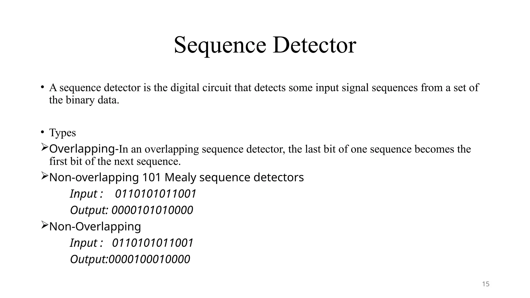
Sequence Detector
• Asequence detector is the digital circuit that detects some input signal sequences from a set of
the binary data.
• Types
Overlapping-In an overlapping sequence detector, the last bit of one sequence becomes the
first bit of the next sequence.
Non-overlapping 101 Mealy sequence detectors
Input : 0110101011001
Output: 0000101010000
Non-Overlapping
Input : 0110101011001
Output:0000100010000
15
16.
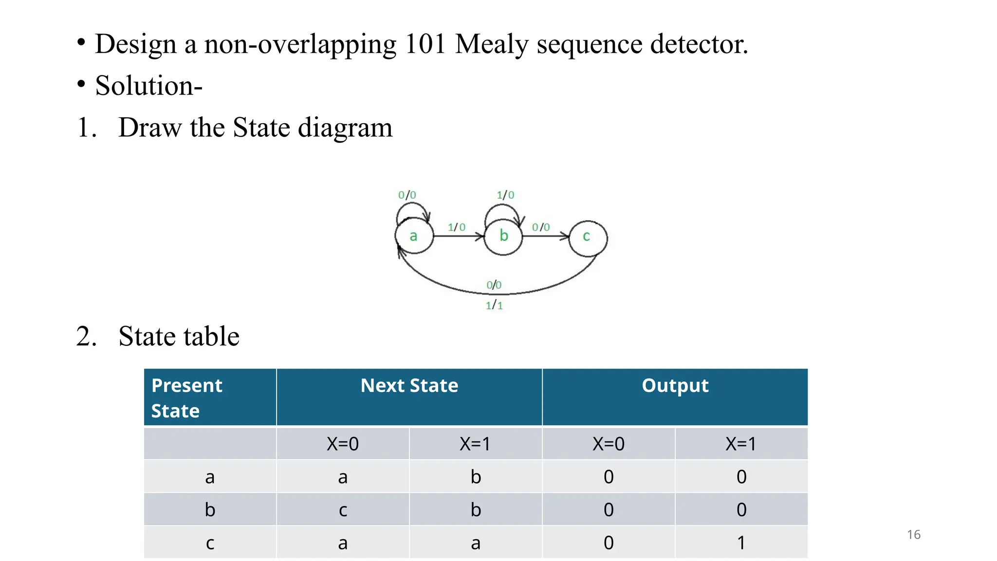
• Design anon-overlapping 101 Mealy sequence detector.
• Solution-
1. Draw the State diagram
2. State table
Present
State
Next State Output
X=0 X=1 X=0 X=1
a a b 0 0
b c b 0 0
c a a 0 1
16
17.
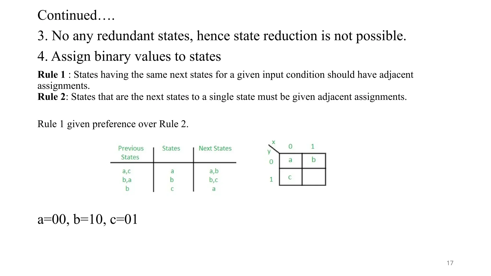
Continued….
3. No anyredundant states, hence state reduction is not possible.
4. Assign binary values to states
Rule 1 : States having the same next states for a given input condition should have adjacent
assignments.
Rule 2: States that are the next states to a single state must be given adjacent assignments.
Rule 1 given preference over Rule 2.
a=00, b=10, c=01
17
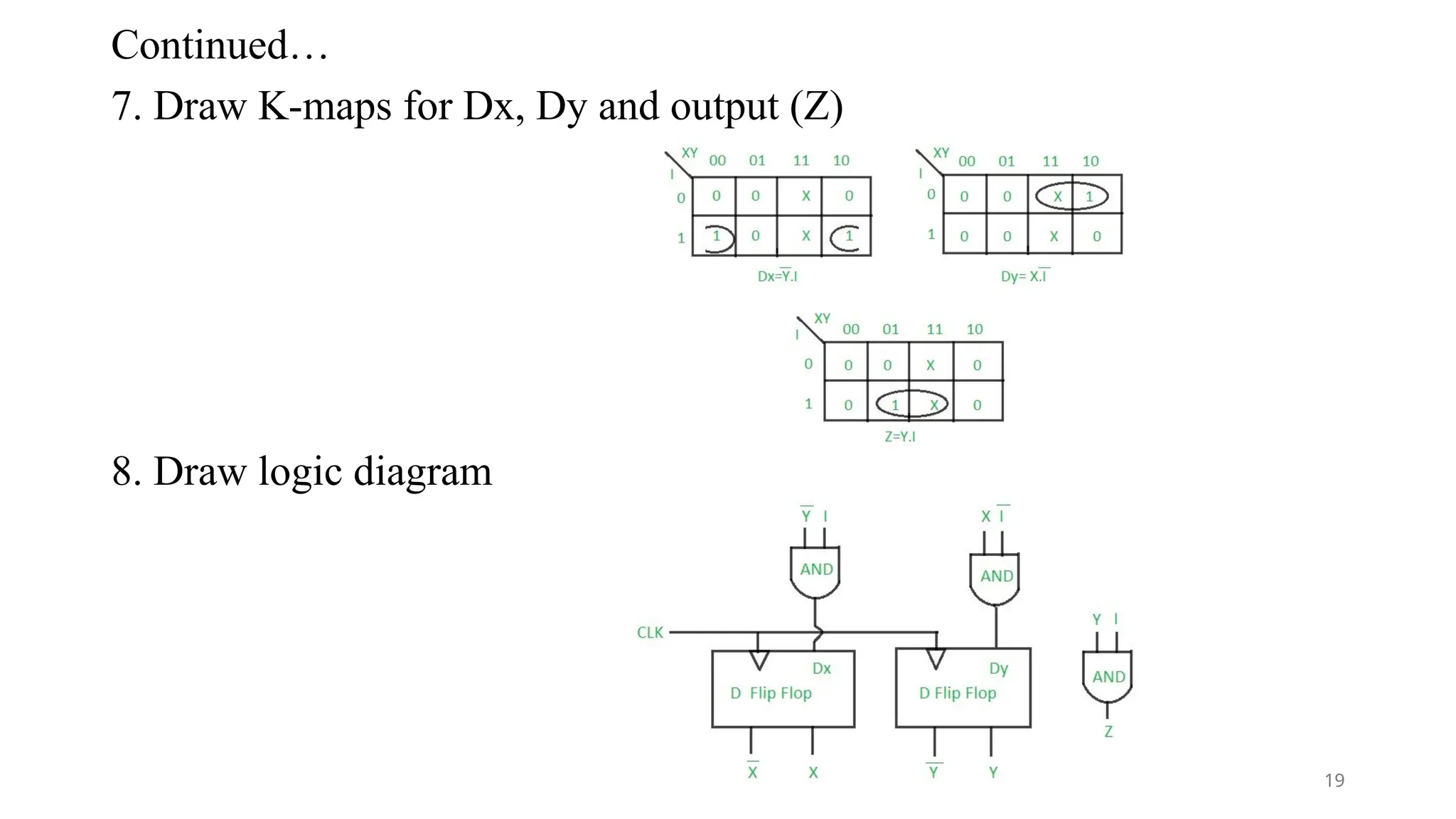
18.
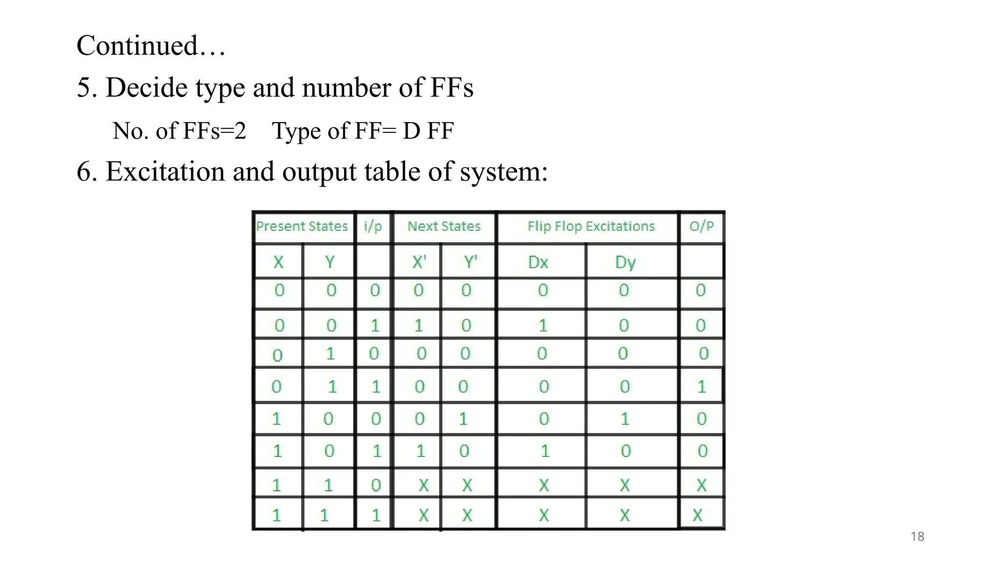
Continued…
5. Decide typeand number of FFs
No. of FFs=2 Type of FF= D FF
6. Excitation and output table of system:
18
Applications of sequencedetector
• Data Compression: It is used in algorithms that need pattern identification for specific sequences of data
storage.
• Control Systems: It is applied in control systems that perform monitoring and decision-making based on
patterns of the input signal observed.
• Bioinformatics: Applied to find specific nucleotide sequences in DNA or RNA for purposes of genetic
analysis and study.
• Pattern recognition: Applied to a vast number of applications from image and machine learning down to
pattern recognition in datasets
• .
• Embedded systems: Embedded systems are applied in microcontrollers as well as digital circuits with
applications requiring control logic to identify sequences.
20
21.
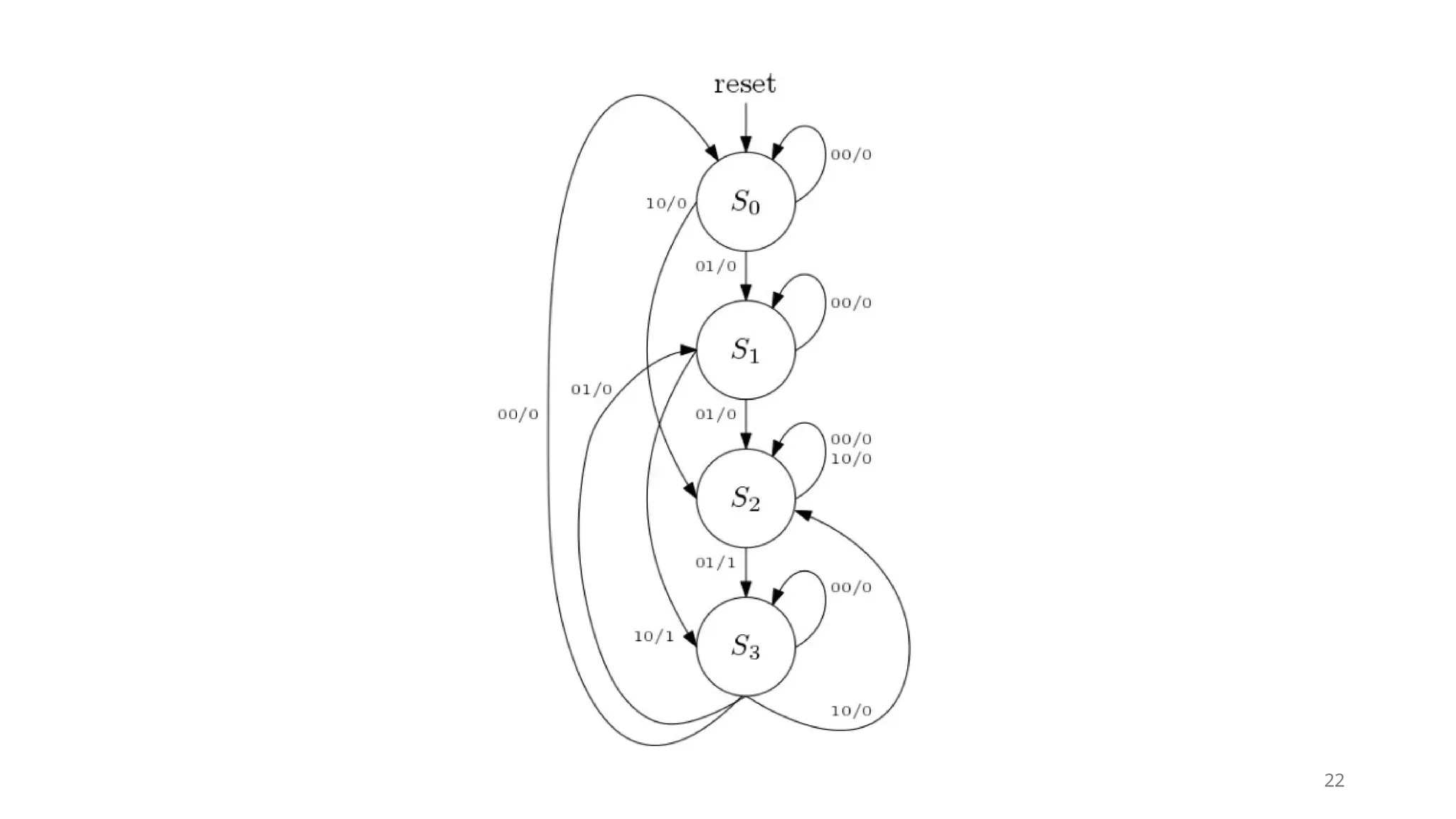
Vending Machine
• Machinedispatches a can of coke after deposition of 15 rupees. The machine has only one hole to
receive coins that means customers can deposit one coin at a time. Also the machine receives only 10
(T) or 5 (F) rupee coin and it doesn’t give any change. So the input din can take values like
1. din = 00, no coin deposited.
2. din = 01, 5 rupee coin (F) deposited.
3. din = 10, 10 rupee coin (T) deposited.
4. din = 11, forbidden – Both coin can’t be deposited at same time.
Also a customer can deposit 15 rupees by the following ways
• 10 + 5 = 15
• 5 + 10 = 15
• 5 + 5 + 5 = 15
If more money is deposited than 15 then the machine will be on the same state asking the customer to
deposit right amount.
21
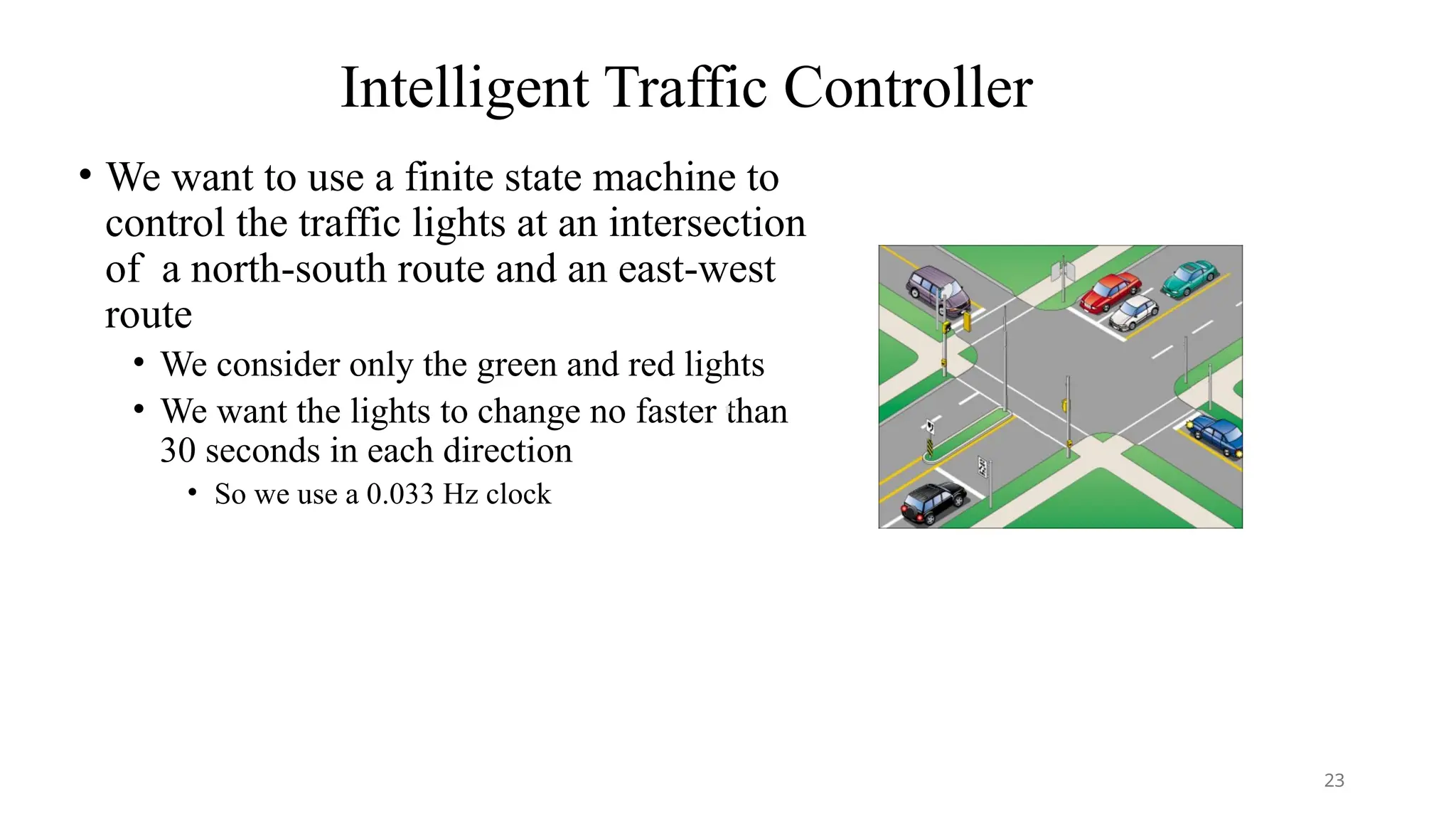
Intelligent Traffic Controller
•We want to use a finite state machine to
control the traffic lights at an intersection
of a north-south route and an east-west
route
• We consider only the green and red lights
• We want the lights to change no faster than
30 seconds in each direction
• So we use a 0.033 Hz clock
23
24.
Intelligent Traffic Controller
•There are two output signals
• NSlite: When the signal is asserted, the light on the north-south route is green;
otherwise, it should be red
• EWlite: When the signal is asserted, the light on the east-west route is green;
otherwise, it should be red
24
25.
Intelligent Traffic Controller
•There are two inputs
• NScar: Indicates that there is at least one car that is over the detectors placed
in the roadbed in the north-south road
• EWcar: Indicates that there is at least one car that is over the detectors placed
in the roadbed in the east-west road
25
26.
Intelligent Traffic Controller
•The traffic lights should only change from one direction to the other
only if there is a car waiting in the other direction
• Otherwise, the light should continue to show green in the same direction
26
27.
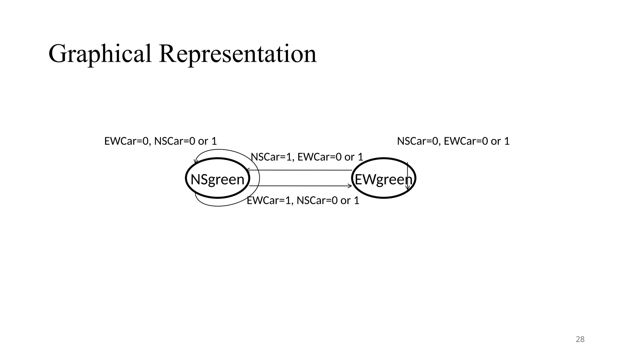
Intelligent Traffic Controller
•Here we need two states
• NSgreen: The traffic light is green in the north-south direction
• EWgreen: The traffic light is green in the east-west direction
27
Examples of FSM
1.Traffic light controller
2. Elevator control system
3. Home automation
4. GUI event handling
5. Natural language processing
6. Robotics and autonomous systems
7. Chatbots and virtual assistants
30
31.
Algorithmic State Machine(ASM)Chart
• It is a special type of flow chart that is used to describe the sequential
operations of a digital circuit.
• The ASM chart determines the sequence of events, timing relationship
between the states of sequential controller ,and the events that happen
while going from one state to another.
• The ASM chart is composed of three basic elements, which are
1. State box
2. Decision box
3. Conditional box
31
32.
Algorithmic State Machine(ASM)Chart
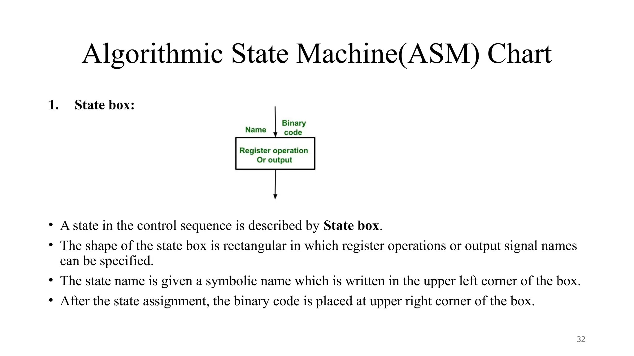
1. State box:
• A state in the control sequence is described by State box.
• The shape of the state box is rectangular in which register operations or output signal names
can be specified.
• The state name is given a symbolic name which is written in the upper left corner of the box.
• After the state assignment, the binary code is placed at upper right corner of the box.
32
33.
Algorithmic State Machine(ASM)Chart
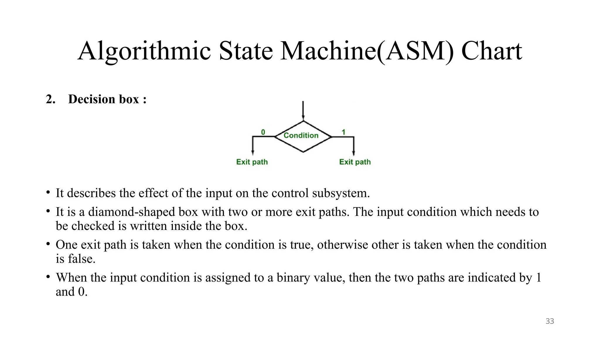
2. Decision box :
• It describes the effect of the input on the control subsystem.
• It is a diamond-shaped box with two or more exit paths. The input condition which needs to
be checked is written inside the box.
• One exit path is taken when the condition is true, otherwise other is taken when the condition
is false.
• When the input condition is assigned to a binary value, then the two paths are indicated by 1
and 0.
33
34.
Algorithmic State Machine(ASM)Chart
3. Condition box :
• It has an oval shape. The input path of the conditional box must come from
the exit path of the decision box.
• The register operations and output lists are written inside the conditional box
which is generated in a particular state but the input condition must be true
34
35.
Ex-ASM Chart for2-bit binary Up counter with enable
line M such that M=1(counting enabled),
M=0(hold present state).
State Diagram ASM Chart
35
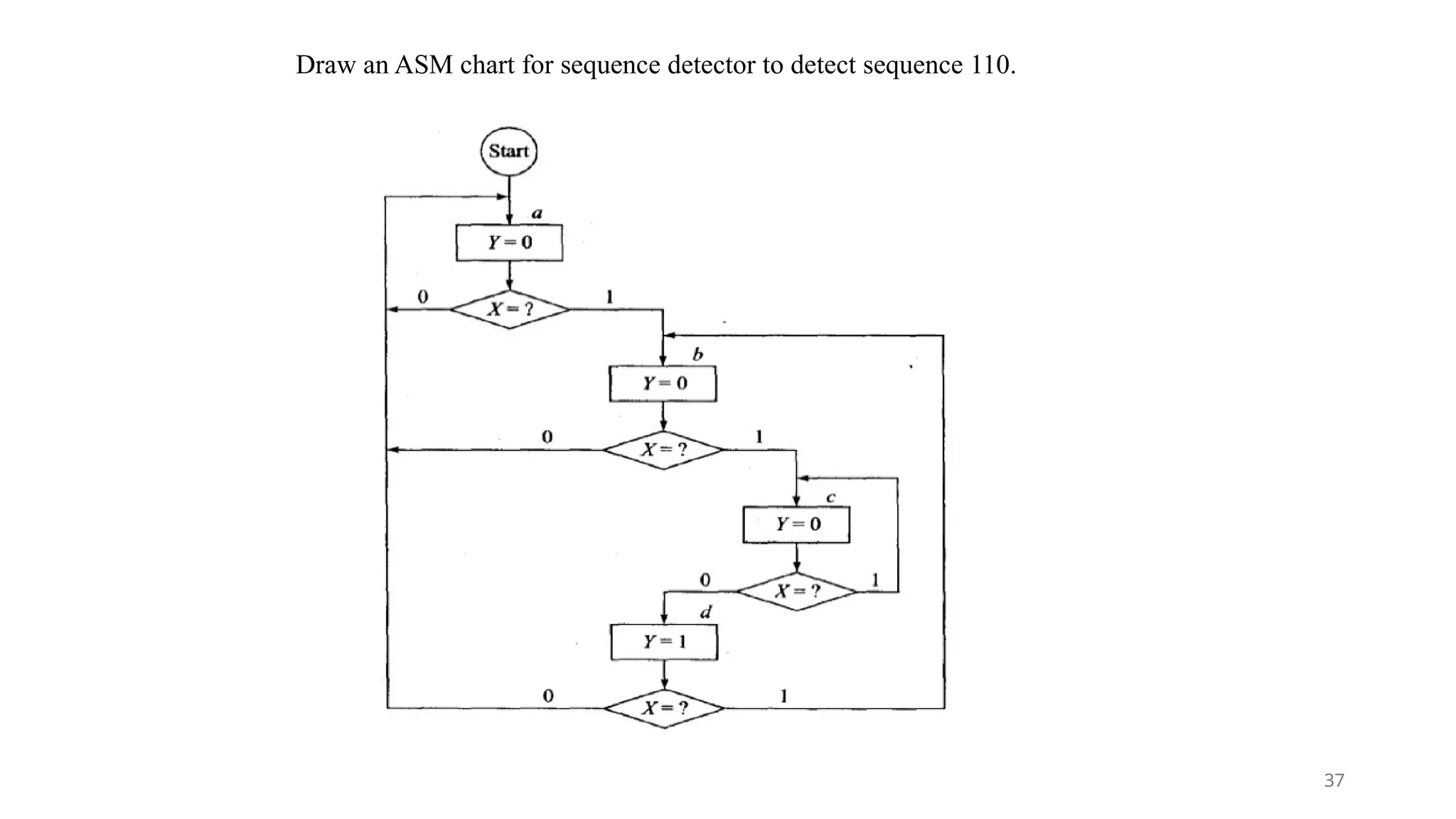
Draw an ASMchart for sequence detector to detect sequence 110.
37
38.
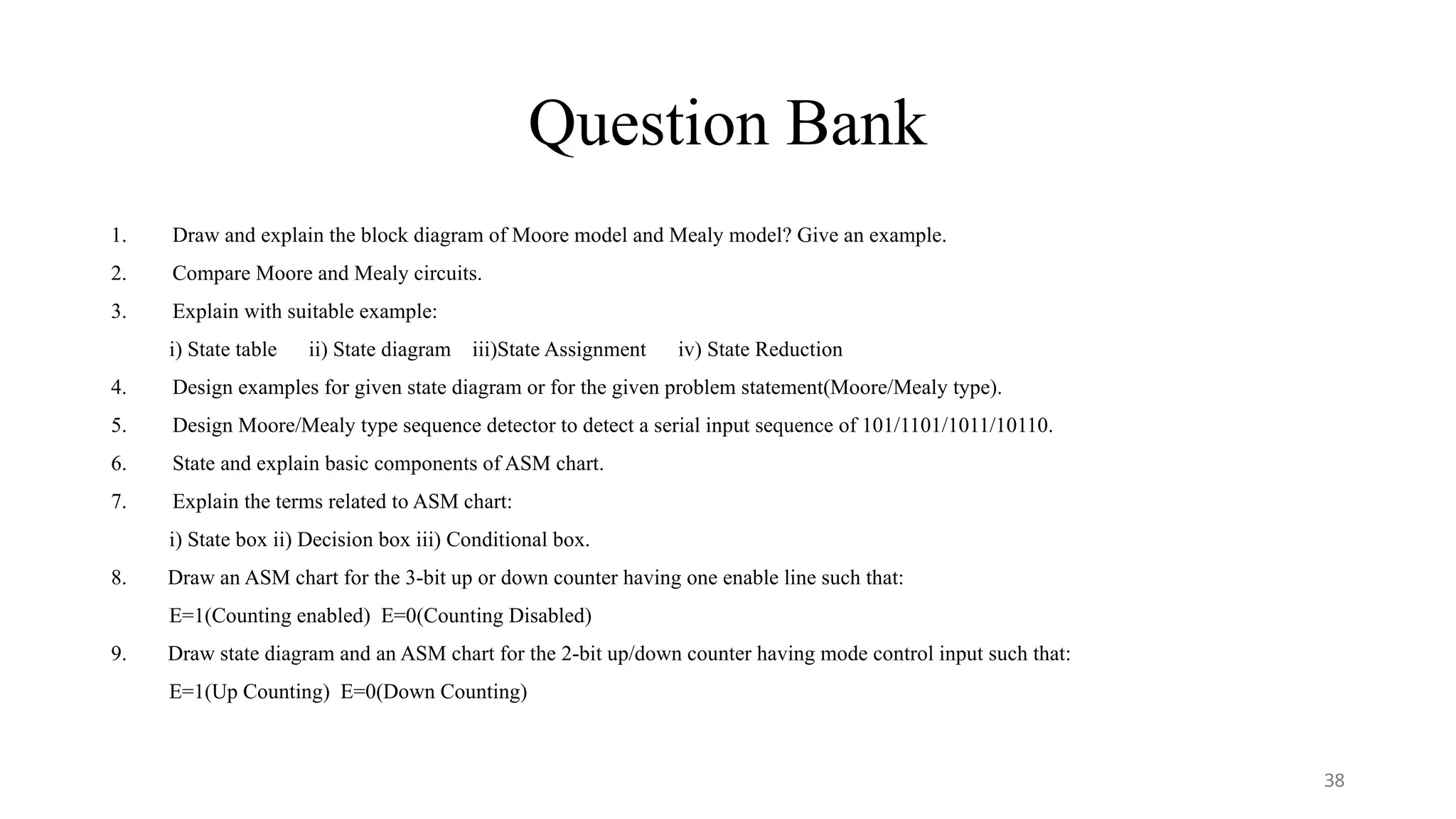
Question Bank
1. Drawand explain the block diagram of Moore model and Mealy model? Give an example.
2. Compare Moore and Mealy circuits.
3. Explain with suitable example:
i) State table ii) State diagram iii)State Assignment iv) State Reduction
4. Design examples for given state diagram or for the given problem statement(Moore/Mealy type).
5. Design Moore/Mealy type sequence detector to detect a serial input sequence of 101/1101/1011/10110.
6. State and explain basic components of ASM chart.
7. Explain the terms related to ASM chart:
i) State box ii) Decision box iii) Conditional box.
8. Draw an ASM chart for the 3-bit up or down counter having one enable line such that:
E=1(Counting enabled) E=0(Counting Disabled)
9. Draw state diagram and an ASM chart for the 2-bit up/down counter having mode control input such that:
E=1(Up Counting) E=0(Down Counting)
38
![Faculty Orientation Workshop
on
SE(E&TC) Revised Syllabus_2024 Course
Digital Electronics
Unit 3: State Machines
under the aegis of
Board of Studies E&TC, SPPU, Pune.
[09/07/2025]
By- Dr. Nilima R. Dhumale
SCOE, Pune 1](https://image.slidesharecdn.com/3unitiiistatemachinesfow-250914164912-ee6313a5/75/3_UNIT-III-State-Machines-DE-SPPU-FOW-pptx-1-2048.jpg)