Download as PPSX, PPTX
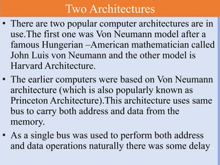
![Load/Store Explanation
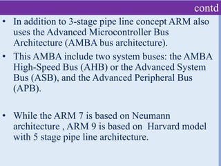
• Let us consider an instruction : LDR R2,[R4]](https://image.slidesharecdn.com/lect-2armprocessors-200724094128/85/Lect-2-ARM-processor-architecture-3-320.jpg)
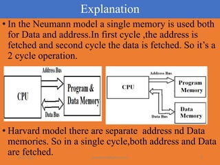
![contd
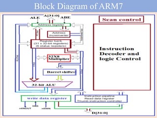
• Let us now consider the instruction : STR R3,[R1].
• Here the data from the register is stored into
memory location.
• The operation is opposite to LDR where data from
memory location is copied to Register.
• Also in STR Rn,[Rx] , Rn is the source and [Rx] is
the destination, which is also opposite as compared
to LDR.
• In LDR R2,[R4] instruction ,[R4] is the source and
R2 is the destination.](https://image.slidesharecdn.com/lect-2armprocessors-200724094128/85/Lect-2-ARM-processor-architecture-4-320.jpg)
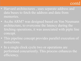
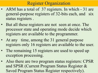
![Load/Store Explanation
• Let us now consider the instruction : STR R3,[R1]](https://image.slidesharecdn.com/lect-2armprocessors-200724094128/85/Lect-2-ARM-processor-architecture-5-320.jpg)

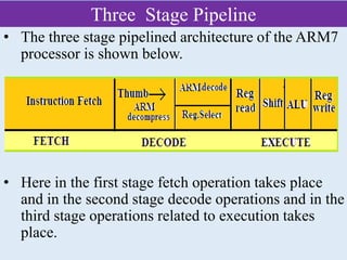
![contd
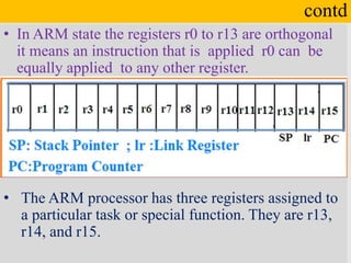
• The general purpose
register usage is given
below.
Ex : MOV r5, r2
ADD r1, r2
LDR r0, [r1]
STR R5,[R0]](https://image.slidesharecdn.com/lect-2armprocessors-200724094128/85/Lect-2-ARM-processor-architecture-15-320.jpg)


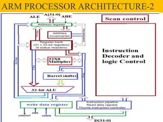
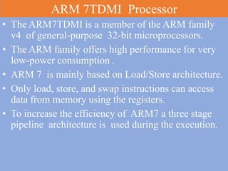
The ARM7TDMI processor, part of the ARM family v4, is a general-purpose 32-bit microprocessor characterized by low power consumption and a load/store architecture utilizing a three-stage pipeline for execution efficiency. It employs the von Neumann architecture but integrates pipeline concepts to enhance instruction execution by allowing concurrent processing. The processor contains 37 registers, with 31 being general-purpose and specific registers designated for tasks such as the stack pointer and program counter.