Download as PDF, PPTX
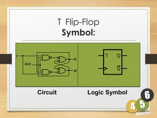
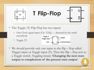
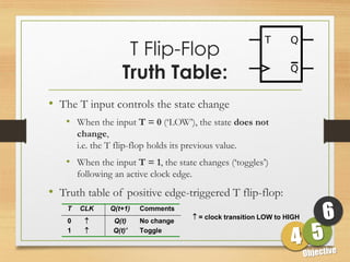
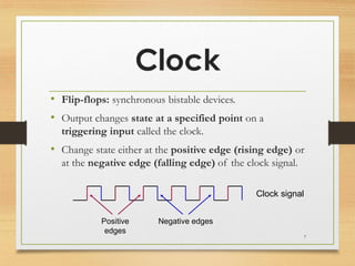
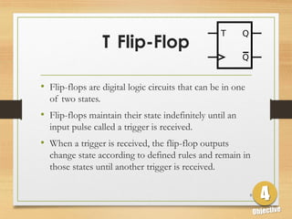
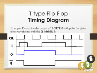
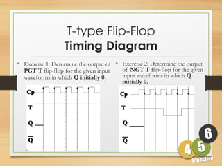

This document defines sequential logic circuits and differentiates them from combinational logic circuits. It describes flip-flops, including SR and T flip-flops. It provides details on building SR and T flip-flops using logic gates, and includes their symbols and truth tables. The document focuses on the T flip-flop, providing its circuit diagram, explaining its toggle function, and including timing diagrams to demonstrate its behavior over multiple clock cycles.


![SEQUENTIAL CIRCUITS [FLIP FLOPS AND LATCHES]](https://cdn.slidesharecdn.com/ss_thumbnails/sequentialcircuits-211203044039-thumbnail.jpg?width=640&height=640&fit=bounds)


