Contents
• Digital circuits
•Finite State Machines (FSM)
• Types of FSM
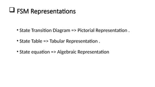
• FSM Representations
• Example for FSM
• Applications of FSM
3.
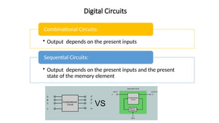
Digital Circuits
• Outputdepends on the present inputs
Combinational Circuits:
• Output depends on the present inputs and the present
state of the memory element
Sequential Circuits:
4.
What is aFinite State Machine?
• FSM is a computational model with a finite number of states.
• FSM is abstract model to represent sequential circuits.
• It transitions between states based on inputs.
• Used to design logic in digital systems.
• FSM Comprises of States (S) which accepts finite set of inputs (I) to produce finite set of outputs
(O)
• It defines two functions;
• State Function: S x I = S
• Machine Function : S x I= O
5.
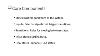
Core Components
• States:Distinct conditions of the system.
• Inputs: External signals that trigger transitions.
• Transitions: Rules for moving between states.
• Initial state: Starting state.
• Final states (optional): End states.
6.
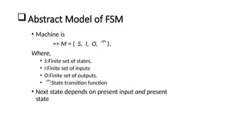
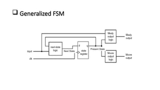
Abstract Model ofFSM
• Machine is
=> M = ( S, I, O, ).
Where,
• S:Finite set of states,
• I:Finite set of inputs
• O:Finite set of outputs.
• :State transition function
• Next state depends on present input and present
state
7.
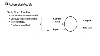
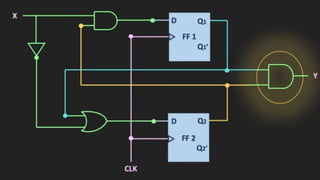
Automata Model:
•Finite State Machine
• Inputs from external world.
• Outputs to external world.
• Internal state.
• Combinational logic.
Next State
Current
State
Input
Output
Registers
Comb.
Logic
8.
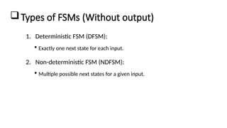
Types of FSMs(Without output)
1. Deterministic FSM (DFSM):
Exactly one next state for each input.
2. Non-deterministic FSM (NDFSM):
Multiple possible next states for a given input.
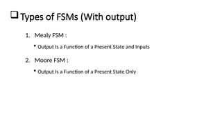
Types of FSMs(With output)
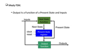
1. Mealy FSM :
Output Is a Function of a Present State and Inputs
2. Moore FSM :
Output Is a Function of a Present State Only
11.
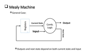
Mealy Machine
Next
State
CurrentState
Input
Output
Registers Comb.
Logic
General Case:
Outputs and next state depend on both current state and input
12.
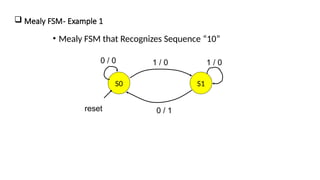
Mealy FSM.
•Output Is a Function of a Present State and Inputs
Next State
function
Output
function
Inputs
Present State
Next State
Outputs
Present State
register
clock
reset
14.
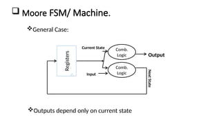
Moore FSM/Machine.
Next
State
Current State
Input
Output
Registers
Comb.
Logic
Comb.
Logic
Outputs depend only on current state
General Case:
15.
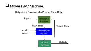
Moore FSM/Machine.
• Output Is a Function of a Present State Only
Present State
register
Next State
function
Output
function
Inputs
Present State
Next State
Outputs
clock
reset
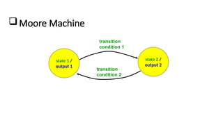
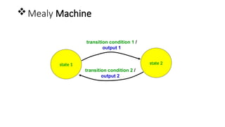
Moore Machine
state 1/
output 1
state 2 /
output 2
transition
condition 1
transition
condition 2
20.
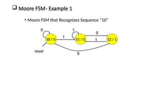
Moore FSM-Example 1
• Moore FSM that Recognizes Sequence “10”
S0 / 0 S1 / 0 S2 / 1
0
0
0
1
1
1
reset
21.
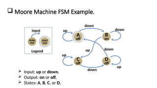
Moore MachineFSM Example.
Legend
state
out
input
start
out
A
off
B
on
C
off
D
off
down
up down
down
up
up
down
up
Input: up or down.
Output: on or off.
States: A, B, C, or D.
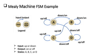
Mealy MachineFSM Example
Legend
state
input/output
start
state
A B
C D
down/on
up/off down/on
down/off
up/off
up/off
down/off
up/off
Input: up or down
Output: on or off
States: A, B, C, or D
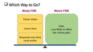
25.
Which Wayto Go?
Safer.
Less likely to affect
the critical path.
Mealy FSM Moore FSM
Lower Area
Responds one clock
cycle earlier
Fewer states
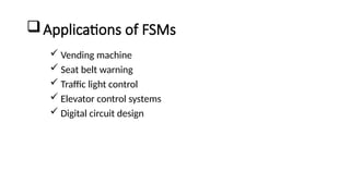
26.
Applications of FSMs
Vending machine
Seat belt warning
Traffic light control
Elevator control systems
Digital circuit design
27.
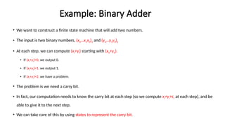
Example: Binary Adder
•We want to construct a finite state machine that will add two numbers.
• The input is two binary numbers, (xn…x1x0)2 and (yn…y1y0)2
• At each step, we can compute (xi+yi) starting with (x0+y0).
• If (xi+yi)=0, we output 0.
• If (xi+yi)=1, we output 1.
• If (xi+yi)=2, we have a problem.
• The problem is we need a carry bit.
• In fact, our computation needs to know the carry bit at each step (so we compute xi+yi+ci at each step), and be
able to give it to the next step.
• We can take care of this by using states to represent the carry bit.
28.
Binary AdderStates
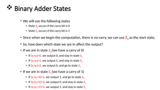
• We will use the following states
• State S0 occurs if the carry bit is 0
• State S1 occurs if the carry bit is 1
• Since when we begin the computation, there is no carry, we can use S0 as the start state,
• So, how does which state we are in affect the output?
• If we are in state S0 (we have a carry of 0)
• If (xi+yi)=0, we output 0, and stay in state S0
• If (xi+yi)=1, we output 1, and stay in state S0
• If (xi+yi)=2, we output 0, and go to state S1
• If we are in state S1 (we have a carry of 1)
• If (xi+yi +1)=1, we output 1, and go to state S0
• If (xi+yi +1)=2, we output 0, and stay in state S1
• If (xi+yi +1)=3, we output 1, and stay in state S1
29.
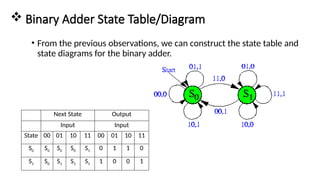
Binary AdderState Table/Diagram
• From the previous observations, we can construct the state table and
state diagrams for the binary adder.
Next State Output
Input Input
State 00 01 10 11 00 01 10 11
S0 S0 S0 S0 S1 0 1 1 0
S1 S0 S1 S1 S1 1 0 0 1