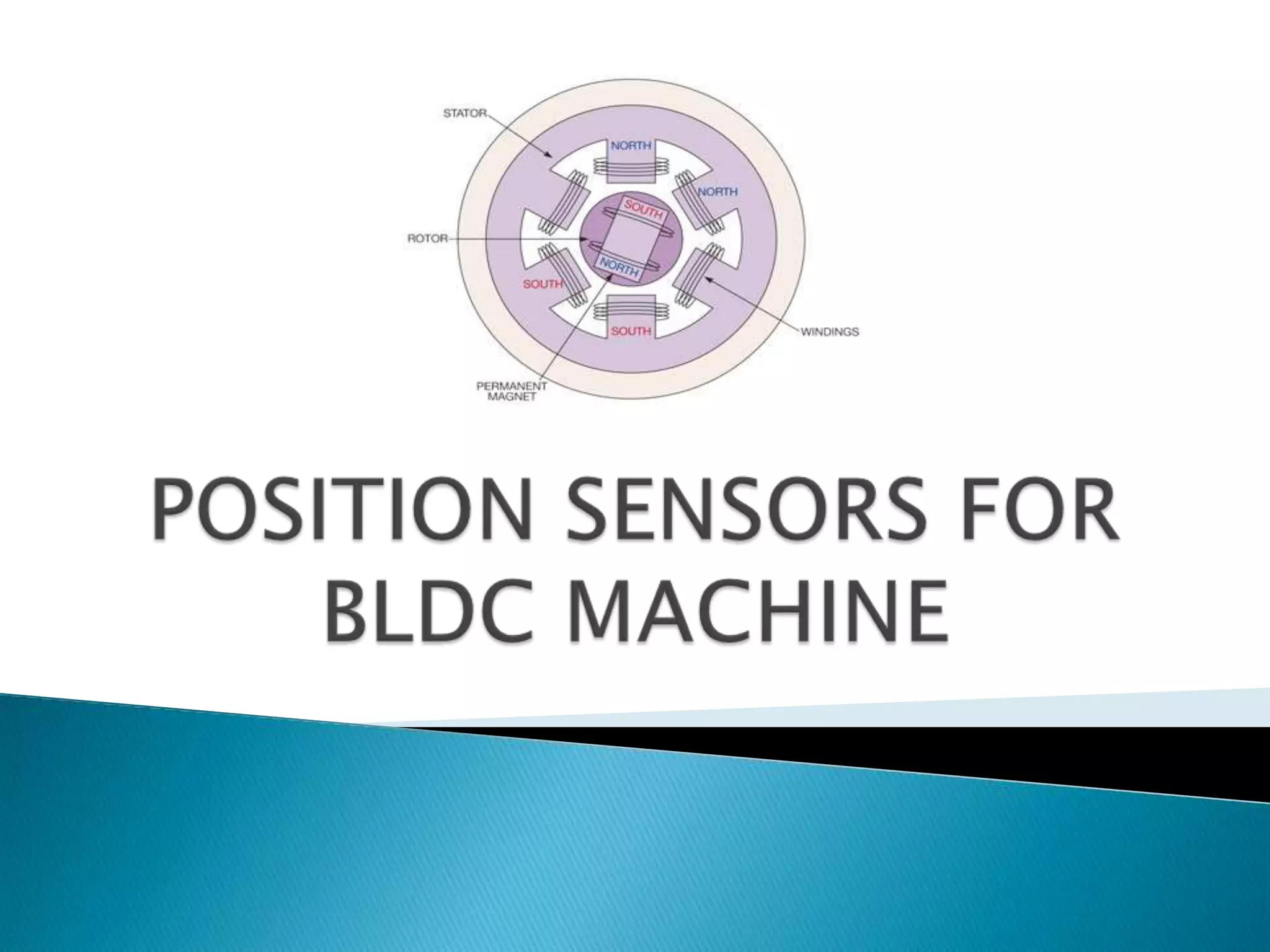
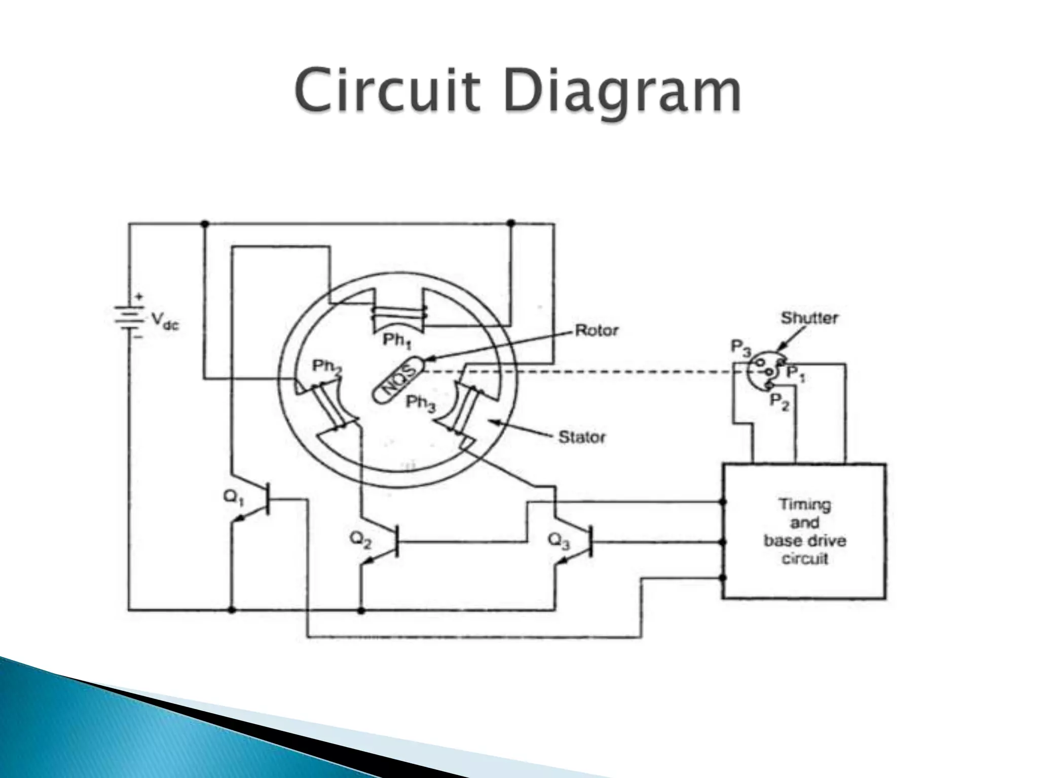
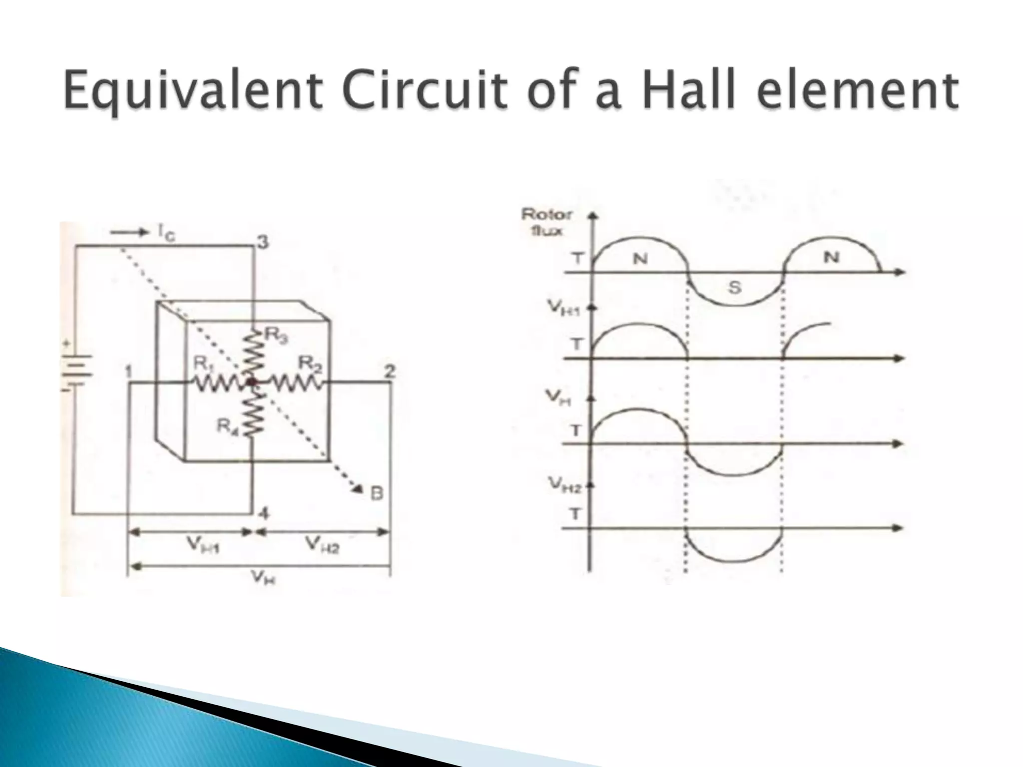
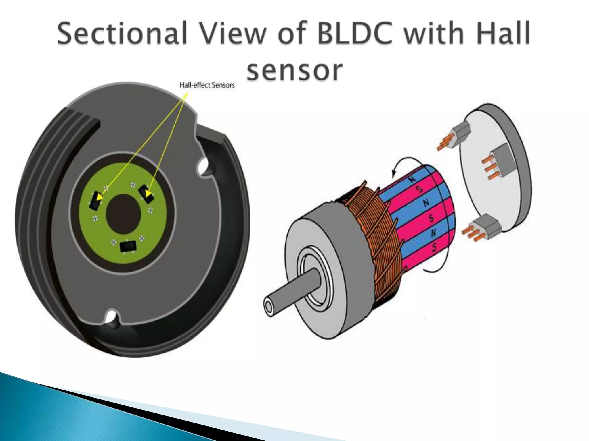
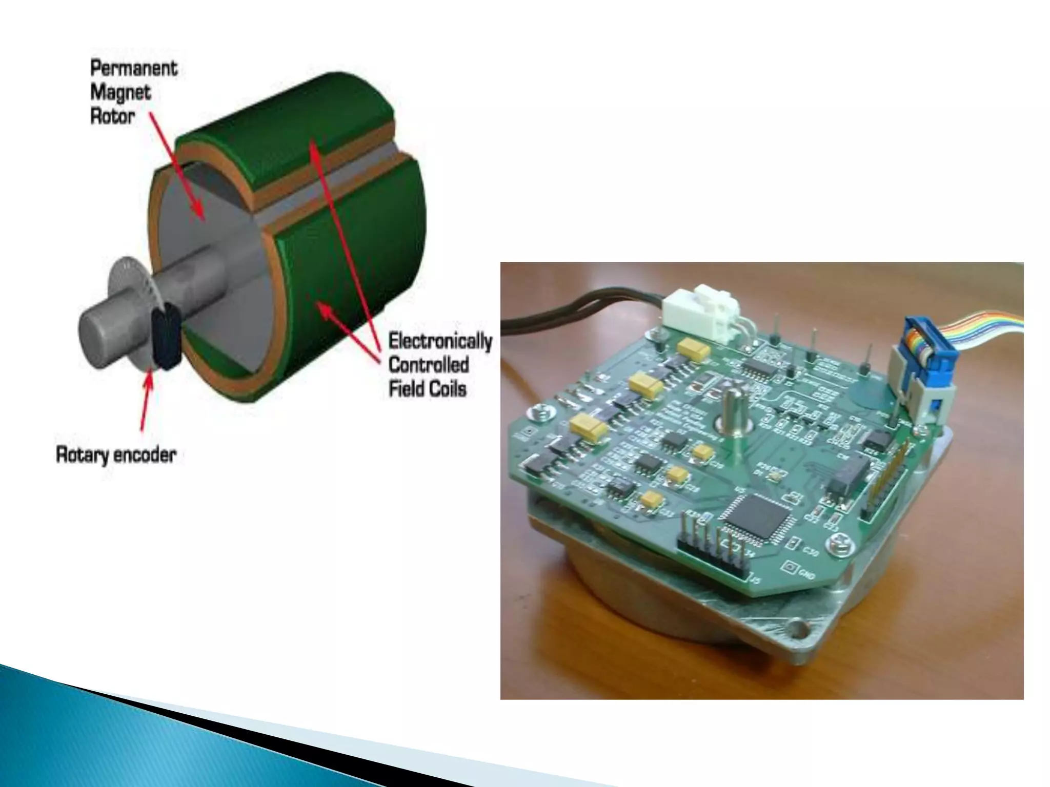
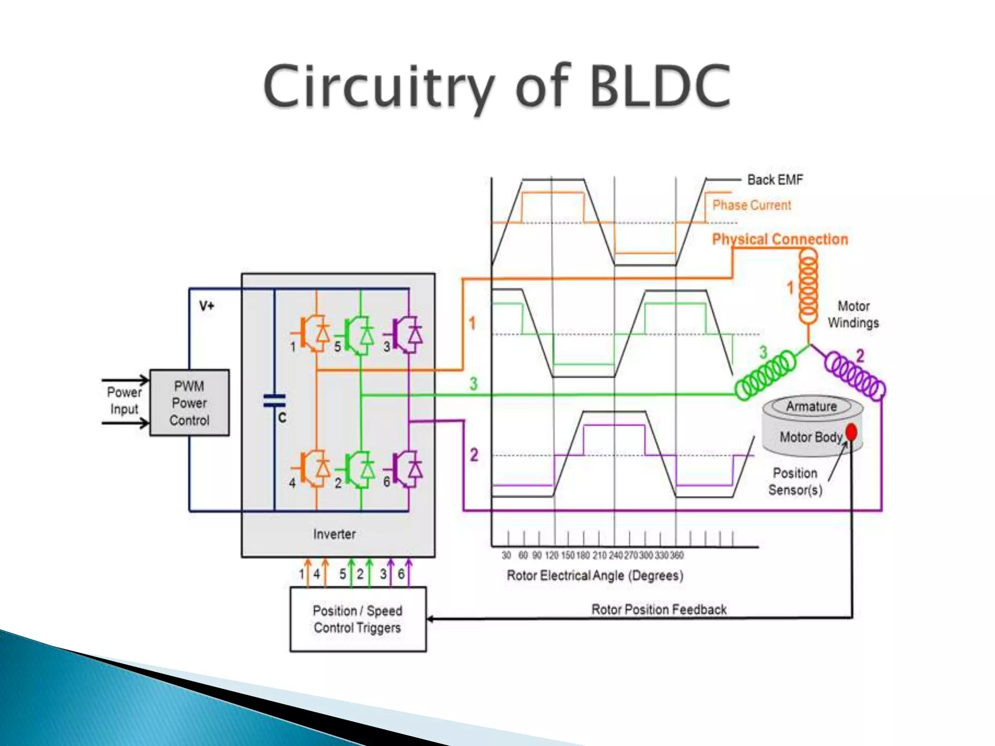
 Acts as feedback
 Sensor – Senses position of rotor
 It converts the information of rotor position
into a suitable electrical signal.
 This signal is used to switch ON and OFF of
various semiconductor devices of electronic
switching circuitry of BLPM motor
 Rotor position can be determined by a Hall
Effect device (or devices), embedded in the
stator, which provide an electrical signal
representing the magnetic field strength. The
amplitude of this signal changes as the magnetic
rotor poles pass over the sensor.
 Other sensing methods are shaft encoders and
also sensing the zero crossing points of currents
generated in the unenergised phase windings.
The latter method is known as "sensorless"
position monitoring.
 Optical position sensor
 Hall effect position sensor
 Electronic position sensors
 Mainly used in Unipolar BLDC machines
 Rotor consists of optical sensors.
 The optical sensor consists of
◦ A light source
◦ three phototransistors P1, P2 and P3 mounted on
the end plate of the motor, separated by 120o
from each other
◦ A revolving shutter coupled to the shaft of the
motor.
 When the shutter revolves, the
phototransistors get exposed to the light in
the sequence of their numbers. In each
revolution, the phototransistors generate the
pulses PI1, PI1 and PI1which have duration and
phase displacement of 120o.
 When light falls on the phototransistors P1, it generates a pulse
and transistor Q1 gets turned on.
 Current starts flowing through stator winding Ph1. This produces
north pole at pole face of Ph1.
 South pole gets attracted towards it and reaches the axis of pole
face of Ph1. Hence rotor revolves in anticlockwise direction.
 During the mean time, the light stops falling on P1 and starts
falling on P2. Hence pulse PI1 is generated which turns on the
transistors Q2.
 Current now starts flowing through the winding Ph2, producing a
north pole. Hence rotor further rotates in anticlockwise direction
so that rotor reaches the axis of the pole face of .
 In the meantime, starts falling on P3. This causes transistors Q3
to turn on which produces north pole at the pole face of Ph3.
 This rotates the rotor further in anticlockwise direction.
 Switching sequence repeats and continuous rotation of the rotor
is obtained.
 The Hall Effect uses three hall sensors within the
Brushless DC Motor to help detect the position of
the rotor.
 The magnetic field changes in response to the
transducer that varies its output voltage.
Feedback is created by directly returning a
voltage, because the sensor operates as an
analogue transducer.
 The distance between the Hall plate and a known
magnetic field can be determined with a group of
sensors, and the relative position of the magnet
can be deduced.
 In a brushless DC motor (BLDC), the
rotor has permanent magnets and the
stator has an electronically-controlled
rotating field, using sensors (rotary
encoders or back-EMF) to detect rotor
position. As such they have no
commutator, and tend to be more
efficient and more powerful than
commutated motors. They do require a
more complicated motor controller.
 High resolution sensing of absolute rotational
position and speed without shaft encoders or
Hall sensors
 High reliability - eliminates mechanical and
optical sensors
 Sensing circuits are integrated with motor
drivers, automatically driving commutation and
providing precise speed and position control
 Uses the magnetic characteristics of the motor to
sense rotor position, eliminating the need for
mechanical adjustments or alignments
 Works at any speed, even while motor is
stopped
 Eases packaging - no requirement to place
components near motor
 No injection of extraneous sense signals into
motor windings
 Works with standard brushless motors
Position sensors
Position sensors

Position sensors

  • 2.
     Acts asfeedback  Sensor – Senses position of rotor  It converts the information of rotor position into a suitable electrical signal.  This signal is used to switch ON and OFF of various semiconductor devices of electronic switching circuitry of BLPM motor
  • 3.
     Rotor positioncan be determined by a Hall Effect device (or devices), embedded in the stator, which provide an electrical signal representing the magnetic field strength. The amplitude of this signal changes as the magnetic rotor poles pass over the sensor.  Other sensing methods are shaft encoders and also sensing the zero crossing points of currents generated in the unenergised phase windings. The latter method is known as "sensorless" position monitoring.
  • 4.
     Optical positionsensor  Hall effect position sensor  Electronic position sensors
  • 5.
     Mainly usedin Unipolar BLDC machines  Rotor consists of optical sensors.  The optical sensor consists of ◦ A light source ◦ three phototransistors P1, P2 and P3 mounted on the end plate of the motor, separated by 120o from each other ◦ A revolving shutter coupled to the shaft of the motor.
  • 8.
     When theshutter revolves, the phototransistors get exposed to the light in the sequence of their numbers. In each revolution, the phototransistors generate the pulses PI1, PI1 and PI1which have duration and phase displacement of 120o.
  • 10.
     When lightfalls on the phototransistors P1, it generates a pulse and transistor Q1 gets turned on.  Current starts flowing through stator winding Ph1. This produces north pole at pole face of Ph1.  South pole gets attracted towards it and reaches the axis of pole face of Ph1. Hence rotor revolves in anticlockwise direction.  During the mean time, the light stops falling on P1 and starts falling on P2. Hence pulse PI1 is generated which turns on the transistors Q2.  Current now starts flowing through the winding Ph2, producing a north pole. Hence rotor further rotates in anticlockwise direction so that rotor reaches the axis of the pole face of .  In the meantime, starts falling on P3. This causes transistors Q3 to turn on which produces north pole at the pole face of Ph3.  This rotates the rotor further in anticlockwise direction.  Switching sequence repeats and continuous rotation of the rotor is obtained.
  • 11.
     The HallEffect uses three hall sensors within the Brushless DC Motor to help detect the position of the rotor.  The magnetic field changes in response to the transducer that varies its output voltage. Feedback is created by directly returning a voltage, because the sensor operates as an analogue transducer.  The distance between the Hall plate and a known magnetic field can be determined with a group of sensors, and the relative position of the magnet can be deduced.
  • 15.
     In abrushless DC motor (BLDC), the rotor has permanent magnets and the stator has an electronically-controlled rotating field, using sensors (rotary encoders or back-EMF) to detect rotor position. As such they have no commutator, and tend to be more efficient and more powerful than commutated motors. They do require a more complicated motor controller.
  • 17.
     High resolutionsensing of absolute rotational position and speed without shaft encoders or Hall sensors  High reliability - eliminates mechanical and optical sensors  Sensing circuits are integrated with motor drivers, automatically driving commutation and providing precise speed and position control  Uses the magnetic characteristics of the motor to sense rotor position, eliminating the need for mechanical adjustments or alignments
  • 18.
     Works atany speed, even while motor is stopped  Eases packaging - no requirement to place components near motor  No injection of extraneous sense signals into motor windings  Works with standard brushless motors