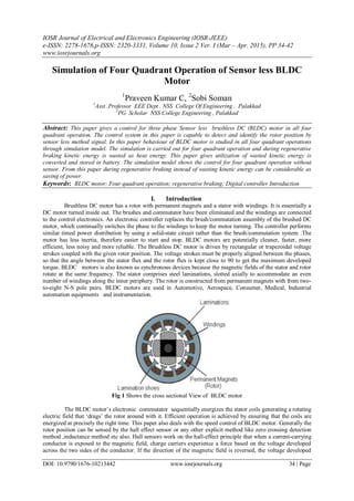
This document summarizes a simulation of four quadrant operation of a sensorless brushless DC motor. It begins with an introduction to brushless DC motors and their operation. It then discusses sensorless control methods, specifically zero crossing detection. The paper presents the mathematical model and Simulink model for simulating four quadrant motor operation including regenerative braking. During regenerative braking, kinetic energy is converted and stored in a battery rather than wasted as heat. The simulation demonstrates control of the motor across four quadrants without position sensors.
A novel approach towards handling of bldc motor drive along with faulty hall ...eSAT Publishing House
IJRET : International Journal of Research in Engineering and Technology is an international peer reviewed, online journal published by eSAT Publishing House for the enhancement of research in various disciplines of Engineering and Technology. The aim and scope of the journal is to provide an academic medium and an important reference for the advancement and dissemination of research results that support high-level learning, teaching and research in the fields of Engineering and Technology. We bring together Scientists, Academician, Field Engineers, Scholars and Students of related fields of Engineering and Technology
Induction motor modelling and applicationsUmesh Dadde
A three-phase induction motor is one of the most popular and versatile motor in electrical
power system and industries. It can perform the best when operated using a balanced three-phase
supply of the correct frequency. In spite of their robustness they do occasionally fail and their
resulting unplanned downtime can prove very costly. Therefore, condition monitoring of
electrical machines has received considerable attention in recent years.
Mathematical Modelling of an 3 Phase Induction Motor Using MATLAB/Simulink IJMER
Mechanical energy is needed in the daily life use as well as in the industry. Induction motors
play a very important role in both worlds, because of low cost, reliable operation, robust operation and low
maintenance. To derive the mathematical model of a 3 phase Induction motor, the theory of reference
frames has been effectively used as an efficient approach. Dynamic models (mathematical models) are
employed in to better understand the behaviour of induction motor in both transient and steady state. The
dynamic modelling sets all the mechanical equations for the inertia, torque and speed versus time. It also
models all the differential voltage, currents and flux linkages between the stationary stator as well as the
moving rotor. This paper presents a step by step Matlab/Simulink implementation of an induction machine
using dq0 axis transformations of the stator and rotor variables in the arbitrary reference frame [1].
SPEED AND TORQUE CONTROL OF AN INDUCTION MOTOR WITH ANN BASED DTCijics
Due to advantages such as fast dynamic response, simple and robust control structure, direct torque
control (DTC) is commonly used method in high performance control method for induction motors. Despite
mentioned advantages, there are some chronically disadvantages with this method like high torque and
current ripples, variable switching behaviour and control problems at low speed rates. On the other hand,
artificial neural network (ANN) based control algorithms are getting increasingly popular in recent years
due to their positive contribution to the system performance. The purpose of this paper is investigating of
the effects of ANN integrated DTC method on induction motor performance by numerical simulations. For
this purpose, two different ANN models have been designed, trained and implemented for the same DTC
model. The first ANN model was designed to select optimum inverter and the second model was designed to
use in the determination of the flux vector position. Matlab/Simulink model of the proposed ANN based
DTC method was created in order to compare with the conventional DTC and the proposed DTC methods.
The simulation studies proved that the induction motor torque ripples have been reduced remarkably with
the proposed method and this approach can be a good alternative to the conventional DTC method for
induction motor control.
Analysis and control of four quadrant operation of three phase brushless dc (...eSAT Publishing House
IJRET : International Journal of Research in Engineering and Technology is an international peer reviewed, online journal published by eSAT Publishing House for the enhancement of research in various disciplines of Engineering and Technology. The aim and scope of the journal is to provide an academic medium and an important reference for the advancement and dissemination of research results that support high-level learning, teaching and research in the fields of Engineering and Technology. We bring together Scientists, Academician, Field Engineers, Scholars and Students of related fields of Engineering and Technology
Induction motor modelling and applications reportUmesh Dadde
A three-phase induction motor is one of the most popular and versatile motor in electrical
power system and industries. It can perform the best when operated using a balanced three-phase
supply of the correct frequency. In spite of their robustness they do occasionally fail and their
resulting unplanned downtime can prove very costly. Therefore, condition monitoring of
electrical machines has received considerable attention in recent years.
Matrix Converter based Direct Torque Control of Induction MotorNeehar NLN
This topic falls under the area of speed control of induction motor. The using of advanced power electronic converters provides better response. In this case, a AC/AC converter is used to control the induction motor.
V/F Control of Squirrel Cage Induction Motor Drives Without Flux or Torque Me...Waqas Tariq
Based on the popular constant volts per hertz principle, two improvement techniques are presented: keeping maximum torque constant or keeping magnetic flux constant. An open-loop inverter-three-phase squirrel-cage induction motor drive system that provides constant maximum torque or increased maximum torque and reduced slip speed at frequencies below the nominal frequency has been modeled, simulated and tested. Load performance analysis of the proposed system under different operation conditions was provided. These principles of operation are extended to the case of operation from variable frequency or variable voltage control method. Finally, the effects of the non-sinusoidal voltage and/or current wave shapes are covered. The results show that both suggested improvement techniques (constant torque or constant flux) improve the steady-state performance A.C. drive system with squirrel cage induction motors. The slip speed has been decreased and the starting torque and maximum torque have been increased, which means that the suggested control techniques can be used in drive systems with short time operating mode under light loads.
Updated field oriented control of induction motor.pptxMohit Sharma
It is a simulation work project done on a 5hp,440V/5A and 1440rpm Induction motor.It explains the control of induction motor using matlab-simulink algorithm by PI control as well as Fuzzy logic control.
Speed Control System of Induction Motor by using Direct Torque Control Method...ijtsrd
Escalator is useful and act in the important part to carry passengers to the targeted floors of building. Every escalator must be driven by its own motor and this motor speed must be controled. To drive escalator with a constant speed, direct torque control technique is used to drive three phase squirrel cage induction motor. In this paper, the development of speed control system for three phase squirrel cage induction motor using a direct torque control method is presented and simulation for proposed system is done with the help of MATLAB SIMULINK. Soe Sandar Aung | Thet Naing Htun "Speed Control System of Induction Motor by using Direct Torque Control Method used in Escalator" Published in International Journal of Trend in Scientific Research and Development (ijtsrd), ISSN: 2456-6470, Volume-3 | Issue-5 , August 2019, URL: https://www.ijtsrd.com/papers/ijtsrd27903.pdfPaper URL: https://www.ijtsrd.com/engineering/electrical-engineering/27903/speed-control-system-of-induction-motor-by-using-direct-torque-control-method-used-in-escalator/soe-sandar-aung
Brushles DC motor are one type of motors that are rapidly gaining the popularity and are penetrating in industrial applications, home appliances, automotive, consumer, medical etc. Because of there many advantages such as high efficiency ,silent operation, compact form ,reliability, low maintenance (due to the absence of brushess), long operating life, high speed ranges etc. for the proper commution of current in inverter the rotar position information is necessary, this information is usually provided by the mechanical position sensors mounted within the motor. however it is well known that these position sensors have many drawbacks therefore a sensor less control of BLDC motor is developed which eliminates the sensing equipment ,reduces the cost of motor and increases the reliability of the BLDC motor. In this paper the position information is obtained from the zero crossing detection of the back EMF which is also called as the terminal voltage sensing method which is the simplest ,method of detecting the back EMF zero crossing ,here the motor voltages are sensed and give to the lowpass filter whose output is give to the ZCD which determines the zero crossing of the back EMF waveform and ZCD generates the signal required for the controller to provide the pulses for the inverter operation the controller used is a high performance controller(DSPic30F4011) which as both the features of microcontroller and digital signal processor .The complete model is simulated in MATLAB/SIMULINK software. the proposed hardware and simulation program are found to be efficient and the results are promising
Speed Control System of Induction Motor by using Vector Control Methodijtsrd
In the Vector Control method of induction motors, one of the advantages of the separately excited DC motor of being able to decouple the flux control and the torque is thereby opened up. The field orientation control of induction motor allows decoupling the control of magnetic flux and the control of the torque produced by the stator current. To drive three phase squirrel cage induction motor with a constant speed, vector control technique is used. In this paper, the development of speed control system for three phase squirrel cage induction motor using a vector control method is presented and simulation for proposed system is done with the help of MATLAB SIMULINK. Soe Sandar Aung | Thet Naing Htun "Speed Control System of Induction Motor by using Vector Control Method" Published in International Journal of Trend in Scientific Research and Development (ijtsrd), ISSN: 2456-6470, Volume-3 | Issue-5 , August 2019, URL: https://www.ijtsrd.com/papers/ijtsrd27914.pdfPaper URL: https://www.ijtsrd.com/engineering/electrical-engineering/27914/speed-control-system-of-induction-motor-by-using-vector-control-method/soe-sandar-aung
The International Journal of Engineering & Science is aimed at providing a platform for researchers, engineers, scientists, or educators to publish their original research results, to exchange new ideas, to disseminate information in innovative designs, engineering experiences and technological skills. It is also the Journal's objective to promote engineering and technology education. All papers submitted to the Journal will be blind peer-reviewed. Only original articles will be published.
IOSR Journal of Mechanical and Civil Engineering (IOSR-JMCE) is an open access international journal that provides rapid publication (within a month) of articles in all areas of mechanical and civil engineering and its applications. The journal welcomes publications of high quality papers on theoretical developments and practical applications in mechanical and civil engineering. Original research papers, state-of-the-art reviews, and high quality technical notes are invited for publications.
Interfacing of Java 3D objects for Virtual Physics Lab (VPLab) Setup for enco...IOSR Journals
During this paper we target the combination of web accessible physics experiments (VPLabs) combined with the Sun’s toolkit for making cooperative 3D virtual worlds. Among such a cooperative setting these tools give the chance for academics and students to figure along as avatars as they control actual instrumentation, visualize natural phenomenon generated by the experiment, and discuss the results. Especially we'll define the steps of integration, future goals, yet because the price of a collaboration area in Wonderland's virtual world.
Effect of Different Physico-Chemical Parameters on Production ofAmylase by Ba...IOSR Journals
The present study is concerned with the production of amylase by Bacillus species strain. In this
study 12 bacterial strains were isolated and screened for their α-amylase activity. These strains were
maintained on nutrient agar medium. Fermentation for the production of amylase was carried out in the enzyme
production medium (EPM). All the 12 strains were tested for amylase production. On the basis of maximum
amylase activity strain no.1 was selected for further studies. Different starch concentrations, 0.75,1.00,1.25%,
pH labels 6.5,7.0,7.5,8.0, aeration (RPM), 100,120,140, temperatures 250C,280C,370C, and 400C and inoculums
level 0.5%,1.0%, 1.5% and 2.0% were studied
Electrochemical, in-vitro in-vivo study of Co (II)-ofloxacin complexIOSR Journals
Ofloxacin complex has been synthesized and screened for its physicochemical, microbial as well as pharmacological activity have been done in solid and aqueous phase. On the basis of elemental analysis, polarographic studies, amperometric titration and IR spectral studies the probable formula for the complex has been determined at 30±1OC and ionic strength of μ= 1.0[KCl]. Raper’s paper disc method was used for microbial study against various pathogenic bacteria and fungi.Invivo syudy of Swiss mice [25-30gm] were used for antibacterial activity against ofloxacin and its complex on xyline-Alcoholic activity test Kidney, liver and serum of these rats were also studied. On the basis of observed result it could be concluded that Co(II)-Ofloxacin complex were found to be non-toxic and more potent than pure Ofloxacin.(1)
Speed Control of BLDC Motor with Four Quadrant Operation Using dsPICijsrd.com
Brushless DC (BLDC) motor drives are becoming more popular in industrial and traction applications. Hence the control of BLDC motor in four quadrants is very vital. The flexibility of the drive system is increased using digital controller. In this paper the PWM signals for driving the power inverter bridge for BLDC motor have been successfully implemented using a dsPIC controller and the motor can be controlled in all the four quadrants without any loss of power .Energy is conserved during regenerative braking period. The digital controller dsPIC, is advantageous over other controller, as it combines the calculation capability of digital signal processor and controlling capability of PIC microcontroller to achieve a precise control. Simulation of the proposed model is done by using MATLAB/Simulink.
International Journal of Engineering Research and Applications (IJERA) is an open access online peer reviewed international journal that publishes research and review articles in the fields of Computer Science, Neural Networks, Electrical Engineering, Software Engineering, Information Technology, Mechanical Engineering, Chemical Engineering, Plastic Engineering, Food Technology, Textile Engineering, Nano Technology & science, Power Electronics, Electronics & Communication Engineering, Computational mathematics, Image processing, Civil Engineering, Structural Engineering, Environmental Engineering, VLSI Testing & Low Power VLSI Design etc.
IJERA (International journal of Engineering Research and Applications) is International online, ... peer reviewed journal. For more detail or submit your article, please visit www.ijera.com
A BL-CSC Converter fed BLDC Motor Drive with Power Factor Correctioniosrjce
This paper presents a power factor correction (PFC) based bridgeless-canonical switching cell
(BL-CSC) converter fed brushless DC (BLDC) motor drive. The proposed BL-CSC converter operating in a
discontinuous inductor current mode is used to achieve a unity power factor at the AC mains using a single
voltage sensor. The speed of BLDC motor is controlled by varying the DC bus voltage of the voltage source
inverter (VSI) feeding BLDC motor via a PFC converter. Therefore, the BLDC motor is electronically
commutated such that the VSI operates in fundamental frequency switching for reduced switching losses.
Moreover, the bridgeless configuration of CSC converter offers low conduction losses due to partial elimination
of diode bridge rectifier at the front end. The proposed configuration shows a considerable increase in
efficiency as compared to the conventional scheme,a combination of switch, capacitor (C1) and diode (D) is
known as a ‘canonical switching cell’ and this cell combined with an inductor (Li) and a DC link capacitor (Cd)
is known as a CSC converter.With proper design and selection of parameters, this combination is used to
achieve PFC operation when fed by a single phase supply via a DBR (Diode Bridge Rectifier) and a DC filter.
Welcome to International Journal of Engineering Research and Development (IJERD)IJERD Editor
call for paper 2012, hard copy of journal, research paper publishing, where to publish research paper,
journal publishing, how to publish research paper, Call For research paper, international journal, publishing a paper, IJERD, journal of science and technology, how to get a research paper published, publishing a paper, publishing of journal, publishing of research paper, reserach and review articles, IJERD Journal, How to publish your research paper, publish research paper, open access engineering journal, Engineering journal, Mathemetics journal, Physics journal, Chemistry journal, Computer Engineering, Computer Science journal, how to submit your paper, peer reviw journal, indexed journal, reserach and review articles, engineering journal, www.ijerd.com, research journals
Closed Loop Speed Control of a BLDC Motor Drive Using Adaptive Fuzzy Tuned PI...IJERA Editor
Brushless DC Motors are widely used for many industrial applications because of their high efficiency, high
torque and low volume. This paper proposed an improved Adaptive Fuzzy PI controller to control the speed of
BLDC motor. This paper provides an overview of different tuning methods of PID Controller applied to control
the speed of the transfer function model of the BLDC motor drive and then to the mathematical model of the
BLDC motor drive. It is difficult to tune the parameters and get satisfied control characteristics by using normal
conventional PI controller. The experimental results verify that Adaptive Fuzzy PI controller has better control
performance than the conventional PI controller. The modeling, control and simulation of the BLDC motor have
been done using the MATLAB/SIMULINK software. Also, the dynamic characteristics of the BLDC motor (i.e.
speed and torque) as well as currents and voltages of the inverter components are observed by using the
developed model.
Fuzzy Logic Controller for Four Quadrant Operation of Three Phase BLDC MotorIJTET Journal
Abstract— Brushless DC (BLDC) motors are one of the electrical drives that are rapidly gaining popularity in industries. In this paper, proposed system gives a three phase Brushless DC (BLDC) in all four quadrant operation by using fuzzy logic controller. The average settling time delay in conventional PI controller drastically overcome by the fuzzy logic controller in order to achieve the constant speed of the motor in any one of the direction respectively. The back EMF is generated during the reverse motoring. In quadrant operation the breaking is applied leads to waste the kinetic energy as heat energy. Utilization of wasted kinetic energy is stored in a battery possible by proposed scheme. The four quadrant operations are Forward Motoring, Forward Braking, Reverse motoring and Reverse Braking. In forward driving the input feed to the BLDC motor up to the set time fastened. Subsequently the Forward Braking is applied then the motor speed reduced to zero. This helps to create a back emf and that is being converted to DC and stored in a battery. Then the Reverse Motoring is applied for rotating the motor at the reverse direction. At last the Reverse Braking is applied it also create the back emf and the converted energy stored in a battery. Rotor position is obtained by the Hall Sensor signal. The system consist of Input source, Fuzzy logic controller, Three phase inverter, Relay, Brushless DC motor (BLDC), Battery, Hall sensor.
Smart TV Buyer Insights Survey 2024 by 91mobiles.pdf91mobiles
91mobiles recently conducted a Smart TV Buyer Insights Survey in which we asked over 3,000 respondents about the TV they own, aspects they look at on a new TV, and their TV buying preferences.
DevOps and Testing slides at DASA ConnectKari Kakkonen
My and Rik Marselis slides at 30.5.2024 DASA Connect conference. We discuss about what is testing, then what is agile testing and finally what is Testing in DevOps. Finally we had lovely workshop with the participants trying to find out different ways to think about quality and testing in different parts of the DevOps infinity loop.
Software Delivery At the Speed of AI: Inflectra Invests In AI-Powered QualityInflectra
In this insightful webinar, Inflectra explores how artificial intelligence (AI) is transforming software development and testing. Discover how AI-powered tools are revolutionizing every stage of the software development lifecycle (SDLC), from design and prototyping to testing, deployment, and monitoring.
Learn about:
• The Future of Testing: How AI is shifting testing towards verification, analysis, and higher-level skills, while reducing repetitive tasks.
• Test Automation: How AI-powered test case generation, optimization, and self-healing tests are making testing more efficient and effective.
• Visual Testing: Explore the emerging capabilities of AI in visual testing and how it's set to revolutionize UI verification.
• Inflectra's AI Solutions: See demonstrations of Inflectra's cutting-edge AI tools like the ChatGPT plugin and Azure Open AI platform, designed to streamline your testing process.
Whether you're a developer, tester, or QA professional, this webinar will give you valuable insights into how AI is shaping the future of software delivery.
Connector Corner: Automate dynamic content and events by pushing a buttonDianaGray10
Here is something new! In our next Connector Corner webinar, we will demonstrate how you can use a single workflow to:
Create a campaign using Mailchimp with merge tags/fields
Send an interactive Slack channel message (using buttons)
Have the message received by managers and peers along with a test email for review
But there’s more:
In a second workflow supporting the same use case, you’ll see:
Your campaign sent to target colleagues for approval
If the “Approve” button is clicked, a Jira/Zendesk ticket is created for the marketing design team
But—if the “Reject” button is pushed, colleagues will be alerted via Slack message
Join us to learn more about this new, human-in-the-loop capability, brought to you by Integration Service connectors.
And...
Speakers:
Akshay Agnihotri, Product Manager
Charlie Greenberg, Host
Encryption in Microsoft 365 - ExpertsLive Netherlands 2024Albert Hoitingh
In this session I delve into the encryption technology used in Microsoft 365 and Microsoft Purview. Including the concepts of Customer Key and Double Key Encryption.
Generating a custom Ruby SDK for your web service or Rails API using Smithyg2nightmarescribd
Have you ever wanted a Ruby client API to communicate with your web service? Smithy is a protocol-agnostic language for defining services and SDKs. Smithy Ruby is an implementation of Smithy that generates a Ruby SDK using a Smithy model. In this talk, we will explore Smithy and Smithy Ruby to learn how to generate custom feature-rich SDKs that can communicate with any web service, such as a Rails JSON API.
Neuro-symbolic is not enough, we need neuro-*semantic*Frank van Harmelen
Neuro-symbolic (NeSy) AI is on the rise. However, simply machine learning on just any symbolic structure is not sufficient to really harvest the gains of NeSy. These will only be gained when the symbolic structures have an actual semantics. I give an operational definition of semantics as “predictable inference”.
All of this illustrated with link prediction over knowledge graphs, but the argument is general.
Transcript: Selling digital books in 2024: Insights from industry leaders - T...BookNet Canada
The publishing industry has been selling digital audiobooks and ebooks for over a decade and has found its groove. What’s changed? What has stayed the same? Where do we go from here? Join a group of leading sales peers from across the industry for a conversation about the lessons learned since the popularization of digital books, best practices, digital book supply chain management, and more.
Link to video recording: https://bnctechforum.ca/sessions/selling-digital-books-in-2024-insights-from-industry-leaders/
Presented by BookNet Canada on May 28, 2024, with support from the Department of Canadian Heritage.
Elevating Tactical DDD Patterns Through Object CalisthenicsDorra BARTAGUIZ
After immersing yourself in the blue book and its red counterpart, attending DDD-focused conferences, and applying tactical patterns, you're left with a crucial question: How do I ensure my design is effective? Tactical patterns within Domain-Driven Design (DDD) serve as guiding principles for creating clear and manageable domain models. However, achieving success with these patterns requires additional guidance. Interestingly, we've observed that a set of constraints initially designed for training purposes remarkably aligns with effective pattern implementation, offering a more ‘mechanical’ approach. Let's explore together how Object Calisthenics can elevate the design of your tactical DDD patterns, offering concrete help for those venturing into DDD for the first time!
GraphRAG is All You need? LLM & Knowledge GraphGuy Korland
Guy Korland, CEO and Co-founder of FalkorDB, will review two articles on the integration of language models with knowledge graphs.
1. Unifying Large Language Models and Knowledge Graphs: A Roadmap.
https://arxiv.org/abs/2306.08302
2. Microsoft Research's GraphRAG paper and a review paper on various uses of knowledge graphs:
https://www.microsoft.com/en-us/research/blog/graphrag-unlocking-llm-discovery-on-narrative-private-data/
UiPath Test Automation using UiPath Test Suite series, part 4DianaGray10
Welcome to UiPath Test Automation using UiPath Test Suite series part 4. In this session, we will cover Test Manager overview along with SAP heatmap.
The UiPath Test Manager overview with SAP heatmap webinar offers a concise yet comprehensive exploration of the role of a Test Manager within SAP environments, coupled with the utilization of heatmaps for effective testing strategies.
Participants will gain insights into the responsibilities, challenges, and best practices associated with test management in SAP projects. Additionally, the webinar delves into the significance of heatmaps as a visual aid for identifying testing priorities, areas of risk, and resource allocation within SAP landscapes. Through this session, attendees can expect to enhance their understanding of test management principles while learning practical approaches to optimize testing processes in SAP environments using heatmap visualization techniques
What will you get from this session?
1. Insights into SAP testing best practices
2. Heatmap utilization for testing
3. Optimization of testing processes
4. Demo
Topics covered:
Execution from the test manager
Orchestrator execution result
Defect reporting
SAP heatmap example with demo
Speaker:
Deepak Rai, Automation Practice Lead, Boundaryless Group and UiPath MVP
Builder.ai Founder Sachin Dev Duggal's Strategic Approach to Create an Innova...Ramesh Iyer
In today's fast-changing business world, Companies that adapt and embrace new ideas often need help to keep up with the competition. However, fostering a culture of innovation takes much work. It takes vision, leadership and willingness to take risks in the right proportion. Sachin Dev Duggal, co-founder of Builder.ai, has perfected the art of this balance, creating a company culture where creativity and growth are nurtured at each stage.
Builder.ai Founder Sachin Dev Duggal's Strategic Approach to Create an Innova...
E010213442
1. IOSR Journal of Electrical and Electronics Engineering (IOSR-JEEE)
e-ISSN: 2278-1676,p-ISSN: 2320-3331, Volume 10, Issue 2 Ver. I (Mar – Apr. 2015), PP 34-42
www.iosrjournals.org
DOI: 10.9790/1676-10213442 www.iosrjournals.org 34 | Page
Simulation of Four Quadrant Operation of Sensor less BLDC
Motor
1
Praveen Kumar C, 2
Sobi Soman
1
Asst .Professor EEE Dept . NSS College Of Engineering , Palakkad
2
PG Scholar NSS College Engineering , Palakkad
Abstract: This paper gives a control for three phase Sensor less brushless DC (BLDC) motor in all four
quadrant operation. The control system in this paper is capable to detect and identify the rotor position by
sensor less method signal. In this paper behaviour of BLDC motor is studied in all four quadrant operations
through simulation model. The simulation is carried out for four quadrant operation and during regenerative
braking kinetic energy is wasted as heat energy. This paper gives utilization of wasted kinetic energy is
converted and stored in battery. The simulation model shows the control for four quadrant operation without
sensor. From this paper during regenerative braking instead of wasting kinetic energy can be considerable as
saving of power.
Keywords: BLDC motor; Four quadrant operation; regenerative braking; Digital controller Introduction
I. Introduction
Brushless DC motor has a rotor with permanent magnets and a stator with windings. It is essentially a
DC motor turned inside out. The brushes and commutator have been eliminated and the windings are connected
to the control electronics. An electronic controller replaces the brush/commutation assembly of the brushed DC
motor, which continually switches the phase to the windings to keep the motor turning. The controller performs
similar timed power distribution by using a solid-state circuit rather than the brush/commutation system .The
motor has less inertia, therefore easier to start and stop. BLDC motors are potentially cleaner, faster, more
efficient, less noisy and more reliable. The Brushless DC motor is driven by rectangular or trapezoidal voltage
strokes coupled with the given rotor position. The voltage strokes must be properly aligned between the phases,
so that the angle between the stator flux and the rotor flux is kept close to 90 to get the maximum developed
torque. BLDC motors is also known as synchronous devices because the magnetic fields of the stator and rotor
rotate at the same frequency. The stator comprises steel laminations, slotted axially to accommodate an even
number of windings along the inner periphery. The rotor is constructed from permanent magnets with from two-
to-eight N-S pole pairs. BLDC motors are used in Automotive, Aerospace, Consumer, Medical, Industrial
automation equipments and instrumentation.
Fig 1 Shows the cross sectional View of BLDC motor
The BLDC motor‘s electronic commutator sequentially energizes the stator coils generating a rotating
electric field that ‗drags‘ the rotor around with it. Efficient operation is achieved by ensuring that the coils are
energized at precisely the right time. This paper also deals with the speed control of BLDC motor. Generally the
rotor position can be sensed by the hall effect sensor or any other explicit method like zero crossing detection
method ,inductance method etc also. Hall sensors work on the hall-effect principle that when a current-carrying
conductor is exposed to the magnetic field, charge carriers experience a force based on the voltage developed
across the two sides of the conductor. If the direction of the magnetic field is reversed, the voltage developed
2. Simulation of Four Quadrant Operation of Sensor less BLDC Motor
DOI: 10.9790/1676-10213442 www.iosrjournals.org 35 | Page
will reverse as well. For Hall effect sensors used in BLDC motors, whenever rotor magnetic poles (N or S) pass
near the hall sensor, they generate a HIGH or LOW level signal, which can be used to determine the position of
the shaft. In a commutation system – one that is based on the position of the motor identified using feedback.
II. Working Principle And Working
The underlying principles for the working of a BLDC motor are the same as for a brushed DC motor;
i.e., internal shaft position feedback. In case of a brushed DC motor, feedback is implemented using a
mechanical commutator and brushes. With a in BLDC motor, it is achieved using multiple feedback sensors.
The most commonly used sensors are hall sensors and optical encoders. In a commutation system one that is
based on the position of the motor identified using feedback two of the three electrical windings are energized at
a time as shown in figure 4.
In figure 4 (A), the GREEN winding labelled ―001‖ is energized as the NORTH pole and the BLUE
winding labelled as ―010‖ is energized as the SOUTH pole. Because of this excitation, the SOUTH pole of the
rotor aligns with the GREEN winding and the NORTH pole aligns with the RED winding labelled ―100‖. In
order to move the rotor, the ―RED‖ and ―BLUE‖ windings are energized in the direction shown in figure 4(B).
This causes the RED winding to become the NORTH pole and the BLUE winding to become the SOUTH pole.
This shifting of the magnetic field in the stator produces torque because of the development of repulsion (Red
winding – NORTH-NORTH alignment) and attraction forces (BLUE winding – NORTH-SOUTH alignment),
which moves the rotor in the clockwise direction. This torque is at its maximum when the rotor starts to move,
but it reduces as the two fields align to each other. Thus, to preserve the torque or to build up the rotation, the
magnetic field generated by stator should keep switching. To catch up with the field generated by the stator, the
rotor will keep rotating. Since the magnetic field of the stator and rotor both rotate at the same frequency, they
come under the category of synchronous motor. This switching of the stator to build up the rotation is known as
commutation. For 3-phase windings, there are 6 steps in the commutation; i.e., 6 unique combinations in which
motor windings will be energized.
A. Hall Sensor and Demerits
Most BLDC motors have three Hall Sensors embedded into the stator on the non-driving end of the
motor. Whenever the rotor magnetic poles pass near the Hall sensors, they give a high or low signal, indicating
the N or S pole is passing near the sensors. Based on the combination of these three Hall sensor signals, the
exact sequence of commutation can be determined. Hall sensors are embedded into the stationary part of the
motor. Embedding the Hall sensors into the stator is a complex process because any misalignment in these Hall
sensors, with respect to the rotor magnets, will generate an error in determination of the rotor position. To
simplify the process of mounting the Hall sensors onto the stator, some motors may have the Hall sensor
magnets on the rotor, in addition to the main rotor magnets. These are a scaled down replica version of the rotor.
Therefore, whenever the rotor rotates, the Hall sensor magnets give the same effect as the main magnets. The
Hall sensors are normally mounted on a PC board and fixed to the enclosure cap on the non-driving end. This
enables users to adjust the complete assembly of Hall sensors, to align with the rotor magnets, in order to
achieve the best performance. Based on the physical position of the Hall sensors, there are two versions of
output. The Hall sensors may be at 60° or 120° phase shift to each other. Based on this, the motor manufacturer
defines the commutation sequence, which should be followed when controlling the motor. But the sensor has
different disadvantages so we go for sensor less methods ,that is it increases the cost , increases the extra
connections and extension ,reduces the system reliability and also difficulties provided in the contaminated
area .Nowadays many research are doing in the sensor less field .
Fig. 1A Phase 1
3. Simulation of Four Quadrant Operation of Sensor less BLDC Motor
DOI: 10.9790/1676-10213442 www.iosrjournals.org 36 | Page
Fig. 2B Phase 2
Fig. 3C Phase 3
Fig. 4D Phase 4
Fig. 5A Phase 5
4. Simulation of Four Quadrant Operation of Sensor less BLDC Motor
DOI: 10.9790/1676-10213442 www.iosrjournals.org 37 | Page
Fig. 6A Phase 6
In this paper the four quadrant operation and regenerative braking achieves of a three phase (star
connection) permanent magnet BLDC motor Without Hall sensor ,while we using Zero crossing Detection
Method for obtaining the rotor position. The four quadrant operations of brushless DC motor mainly helps in the
locomotive of train systems for frequently reversal of command. The proposed digital control of four quadrant
operation system performs the following tasks. i.e.
speed controlling
Regenerative braking and
Utilize the wasted kinetic energy.
Fig .3 shows the block diagram of speed controlling of the BLDC Motor. The dspic or pic digital
controller is used for control and determines the motor operation for different quadrant and regenerative
braking .Generally the which is very advantageous over other controllers, as it combines the calculation
capability of Digital Signal Processor and controlling capability of Pic microcontroller, to achieve precise
control.
Fig. 7 Speed control of BLDC Motor.
When the regenerative braking is applied normally closed (NC) contacts opens and normally open
contacts (NO) contacts closes, hence wasting kinetic heat energy wasted in the motor the back EMF voltage
utilized by three phase rectifier circuit to charge the battery. In fact the wasted energy is conserved and saving in
regenerative braking operation. The arrangement of schematic diagram as shown in the below figure .3
Fig. 4 Schematic Diagram of Proposed BLDC Motor
5. Simulation of Four Quadrant Operation of Sensor less BLDC Motor
DOI: 10.9790/1676-10213442 www.iosrjournals.org 38 | Page
III. Four Quadrant Control Operation
There are four possible modes or quadrants of operation using a three phase Brushless DC (BLDC)
Motor. In 1st
Quadrant positive speed and the torque is positive hence the motor rotates in the forward direction. .
In 2nd Quadrant motor is rotating in the forward direction, but torque is being applied in reverse. Reverse
Torque is applied to ―brake‖ the motor, and the motor is now generating power. In 3rd Quadrant negative speed
and negative torque. In this condition the motor is rotating in reverse direction. in 4th Quadrant exactly the
opposite. The motor is rotates in the reverse direction, but the torque is being applied in the forward direction.
Again, torque is being applied to attempt to slow the motor and change its direction to forward again. Once
again, power is being generated by the motor .In this paper uses the motoring and regenerative mode.
Fig. 5 Four Quadrant Operation Of BLDC Motor
The three phase brushless DC (BLDC) motor is initially made to rotate in forward direction, but when
the speed command is given reverse, the control goes into the forward braking mode hence current flows from
motor to battery , in this case the rotor comes to the standstill position is term named as forward braking or
regenerative braking. Instead of waiting for the absolute standstill position, continuous energization of the main
phase is attempted. This rapidly slows down the rotor to a standstill position. Similarly for when the motor
rotates in the reverse direction, but when the speed command is given positive, the controller goes into reverse
regeneration mode, in this case the current is flows from motor to source.
B. Regenerative Braking
Electrical Braking is mainly two types one is dynamic braking another one is Regenerative braking .BLDC
Hub motor used in e-bike applications .Regenerative braking stores energy into the battery ,while increasing the
life of motor. During braking(off time) mode or instead of wasting kinetic energy can be considerable as saving
of power and also increases the reliability by the elimination of Hall sensor .That is implement in the simulation.
IV. Mathematical Model
The BDCM has three stator windings and permanent magnets on the rotor. Since both the magnet and
the stainless steel retaining sleeves have high resistivity, rotor-induced currents can be neglected. Hence the
circuit equations of the three windings in phase variables are
= …..(1)
Where it has been assumed that the stator resistances of all the windings are equal. The back EMF's eR, eY, and
eB, have trapezoidal shapes. Assuming further that there is no change in the rotor reluctances with angle, the
LR = LY = LB = L s
LRY=LRB=LBY=M
Hence
= ……(2)
6. Simulation of Four Quadrant Operation of Sensor less BLDC Motor
DOI: 10.9790/1676-10213442 www.iosrjournals.org 39 | Page
But iR= iY= IB=0
Assuming constant self and mutual inductance, the voltage equation becomes
=
In state space form the equation is arranged as
……….(3)
The electromagnetic torque is given as
The equation of motion is given as
V. Simulink Model
The source to the BLDC motor is AC supply which is converted to DC through VSI. Here six switch 3
legs inverter is used. MOSFET is used as switch in order to control the speed of the motor. Simulink model can
drawn with the help of schematic diagram of the proposed Sensor less BLDC control.
A. Circuit Description
The simulink model of the BLDC motor is shown in fig.6. Permanent Magnet Synchronous motor with
trapezoidal back EMF is modelled as a Brushless DC Motor. A three-phase motor rated 1 kW, 500 Vdc, 2000
rpm is fed by a six step voltage inverter. The inverter is a MOSFET bridge of the SimPowerSystems library. A
speed regulator is used to control the DC bus voltage and it is compared with the zero crossing back emf output..
The three-phase output of the inverter are applied to the PMSM block's stator windings. Two control loops are
used. The inner loop synchronises the inverter gates signals with the electromotive forces. The outer loop
7. Simulation of Four Quadrant Operation of Sensor less BLDC Motor
DOI: 10.9790/1676-10213442 www.iosrjournals.org 40 | Page
controls the motor's speed by varying the DC bus voltage. The difference between the required speed and the
actual speed is input into the PI controller, which then modulates the duty cycle of the PWM based on the error
signal obtained by the difference between the actual speed and required speed. Different type of another MAT
Lab Blocks are used like MAT Lab Functions Converter , Signal Builder etc. Signal Builder-Create and
generate interchangeable groups of signals whose waveforms are piecewise linear. The Direct Lookup Table (n-
D) block uses inputs as zero-based indices into an n-dimensional table. The number of inputs varies with the
shape of the output: an element, column, or 2-D matrix. We define a set of output values as the Table data
parameter. The first input specifies the zero-based index to the table dimension that is one higher than the output
dimensionality. FCn-General expression block. Use "u" as the input variable name. Converter- Convert the input
to the data type and scaling of the output. MAT Lab functions are used to create or edit a call back function for
those block select it in the call back list. Then enter the MAT Lab CODE that implemented the function in the
content pane .In this block represented the duration and condition the forward motoring reveres motoring
forward braking reverse braking. The conversion has two possible goals. One goal is to have the Real World
Values of the input and the output be equal. The other goal is to have the Stored Integer Values of the input and
the output be equal. Overflows and quantization errors can prevent the goal from being fully achieved .In this
Simulink Zero cross is a subsystem and conditions for getting the zero position of the rotor signal that is
compared with the rotor speed .The Back emf and speed are expressed in the value so we use the convert tool
for converting to the signal ,that is the part of the sensor less method. Next sub system is the MAT Lab function
the time duration of the quadrant operation is given to this block, as per this coding the controlling of these
quadrant is possible that are shown in Wave forms. We set the time duration of quadrant in the signal builder
that is forward motoring(0-0.1),reverse braking (0.1-0.2),reverse motoring (0.2-0.4) .Six gate signals are
produced to control the on and off period of the switches associated in the power electronic circuit. In this
simulation the (rotor position) can be getting from zero crossing subsystem ,that provide the signals as per the
condition if the signal is compared to Zero and one and obtained the PWM signal. When the motor runs in the
forward motoring at 2000 rpm ,while there is no voltage stored in the battery. But motor runs in braking
quadrant while the voltage stored in the battery. Motor runs in the reverse direction while the speed of motor is -
2000 rpm. These are clearly shown in the wave .The total harmonic distortion of battery is also obtained.
When the nominal torque is applied, the stator current increases to maintain the nominal speed. The
saw tooth waveform is also observed in the electromagnetic torque signal Te. However, the motor's inertia
prevents this noise from appearing in the motor's speed waveform. When the motor is in the braking mode or
stand still condition while kinetic energy stored to the battery through a rectifier that are shown in the wave
form .
Fig 7: Input of the Motor
Fig. 8 Output of the Battery
8. Simulation of Four Quadrant Operation of Sensor less BLDC Motor
DOI: 10.9790/1676-10213442 www.iosrjournals.org 41 | Page
Fig. 9 Rotor speed in all quadrants
Fig.10 Back Emf of all Quadrants
Fig. 11 Gate signal for Six switches
VI. Simulation Result
The waveform shows the trapezoidal wave, Rotor speed Back emf voltage from the sensor less method.
The voltage and current of the battery shown the value of motoring is 0 Vand 0 A But in the braking time the
battery volage is increased to300V and current is 0.29 A, while the motoring time the relay contact is open and
does not store any energy .The Total Harmonic Distrotion of the battery output is 82.67% based on the 50Hz
fundamental frequency. The rotor speed, output of the battery and back emf (sesnsor less method),these are
provided the time for motoring braking as per the mat lab function. The oscillations die out gradually as the
motor changes its direction of rotation. The Pulse Width Modulation or gate signal (PWM) pulses applied to the
inverter circuit at the appropriate time to trigger the appropriate switches are the control signals to the circuit. It
depicts that the motor is running in the forward direction, after a time interval brake is applied, the motor stops
decelerating at this point the battery starts charging. The battery is energized during the regenerative period.
VII. Conclusions
This paper shows the simulation of the Digital Controlled four Quadrant Operation Of Sensor less
BLDC Motor. The main advantages of this proposal the saving of energy in the regenerative braking time and
9. Simulation of Four Quadrant Operation of Sensor less BLDC Motor
DOI: 10.9790/1676-10213442 www.iosrjournals.org 42 | Page
also the effectiveness of the sensor less. The time taken to achieve this braking is comparatively less. The
generated voltage during the regenerative mode can be returned back to the supply mains which will result in
considerable saving of power. This concept may well be utilized in the rotation of spindles, embroidery
machines and electric vehicles where there is frequent reversal of direction of rotation of the motor .In the
contaminated situation this proposal more effective The significant advantages of the proposed work are: simple
hardware circuit, reliability of the control algorithm, excellent speed control, smooth transition between the
quadrants and efficient conservation of energy is achieved with and without
load conditions .Simulation result shows DC output and battery energization when the motor is in braking
condition.
About The Authors
Mr Praveen Kumar C is working as Assistant Professor in the Department of Electrical and Electronics
Engineering at NSS College of Engineering, Palakkad, Kerala. He received the ME Degree in Mechatronics
from Anna University in 2013. His areas of interest include Special Machines, Linear Machines and Jet
propulsion.
Ms Sobi Soman is pursuing her M Tech degree in Power Electronics at NSS College of Engineering,
Palakkad. She is doing her Master Research Project in the area of Brushless DC Motor .
References
[1]. C. S. Joice, Dr. S. R. Paranjothi, and Dr. V. J. S. Kumar, ―Practical implementation of four quadrant operation of three phase
Brushless DC motor using dsPIC,‖ in Proc. IConRAEeCE 2011, 2011, pp. 91.97, IEEE.
[2]. P. Yedamale, Microchip Technology Inc., ―Brushless DC (BLDC) motor fundamentals,‖ 2003, AN885.
[3]. B. Singh and S. Singh ―State of the art on permanent magnet brushless DC motor drives,‖ J. Power Electron., vol. 9, no. 1, pp. 1–
17, Jan,09.
[4]. L. N. Elevich, ―3-phase BLDC motor control with hall sensors using 56800/E digital signal controllers,‖ AN1916, Application
Note, Rev. 2.0, 11/2005.
[5]. Afjei, O. Hashemipour, M. A. Saati, and M. M. Nezamabadi, ―A new hybrid brushless DC motor/generator without permanent
magnet,‖ IJE Trans. B: Appl., vol. 20, no. 1, pp. 77–86, Apr. 2007.
[6]. C. Xia, Z. Li, and T. Shi, ―A control strategy for four-switch three brushless DC motor using single current sensor,‖ IEEE Trans.
Ind. Electron., vol. 56, no. 6, pp. 2058–2066, June 2009.
[7]. C.-W. Hung, C.-T. Lin, C.-W. Liu, and J.-Y. Yen, ―A variable sampling controller for brushless DC motor drives with low-
resolution position sensors,‖ IEEE Trans. Ind. Electron., vol. 54, no. 5,pp 2846–2852, Oct. 2007.
[8]. R. Krishnan, S.-Y. Park, and K. Ha, ―Theory and operation of a four quadrant switched reluctance motor drive with a single
controllable switch—the lowest cost four-quadrant brushless motor drive,‖ IEEE Trans. Ind. Appl., vol. 41, no. 4, pp. 1047–1055,
2005.
[9]. A. Sathyan,M. Krishnamurthy, N.Milivojevic, and A. Emadi, ―A Low cost digital control scheme for brushless DC motor drives in
domestic applications,‖ in Proc. Int. Electric Machines Drives Conf., 2009,pp 76–82.
[10]. W. Cui, H. Zhang, Y.-L. Ma, and Y.-J. Zhang, ―Regenerative braking control method and optimal scheme for electric motorcycle,‖
in Proc. Int. Conf. Power Engineering, Energy and Electrical Drives, Spain, 2011, pp. 1–6.
[11]. M. K. Yoong, Y. H. Gan, G. D. Gan, C. K. Leong, Z. Y. Phuan, B. K. Cheah, and K. W. Chew, ―Studies of regenerative braking in
electric vehicle,‖ in Proc. IEEE Conf. Sustainable Utilization Development Eng. Technol., Malaysia, Nov. 2010, pp. 40–45.
[12]. M.-F. Tsai, T. PhuQuy, B.-F. Wu, and C.-S. Tseng, ―Model construction and verification of a BLDC moto r using
MATLAB/SIMULINK and FPGA control,‖ in Proc. 6th IEEE Conf. Ind Electron. Appl., Beijing, 2011, pp. 1797–1802.