Downloaded 291 times


![0.00 125.00 250.00 375.00
ElectricalDegree [deg]
3.75
2.50
1.25
0.00
PhaseCurrent1a [A]
-1.25
-2.50
-3.75
XY Plot 1 RMxprtDesign1 ANSOFT
Curve Info
PhaseCurrent1a
Setup1 : Performance
0.00 125.00 250.00 375.00
ElectricalDegree [deg]
3.75
2.50
1.25
0.00
PhaseCurrent1b [A]
-1.25
-2.50
-3.75
XY Plot 2 RMxprtDesign1 ANSOFT
Curve Info
PhaseCurrent1b
Setup1 : Performance
0.00 125.00 250.00 375.00
ElectricalDegree [deg]
3.75
2.50
1.25
0.00
PhaseCurrent1c [A]
-1.25
-2.50
-3.75
XY Plot 3 RMxprtDesign1 ANSOFT
Curve Info
PhaseCurrent1c
Setup1 : Performance
Phase A
Phase B
Phase C
17](https://image.slidesharecdn.com/projectfinal-141109001730-conversion-gate01/85/Three-phase-BLDC-motor-17-320.jpg)


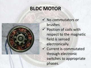
This document presents a comprehensive guide on Brushless DC (BLDC) motors, discussing their advantages over traditional DC motors, including higher efficiency, noiseless operation, and compact design. It outlines the design, analysis, fabrication, and control circuit of a specific BLDC motor project, detailing specifications, testing methods, and future developments. The document concludes with a schedule and manufacturing cost breakdown for the motor components.