Download as PDF, PPTX
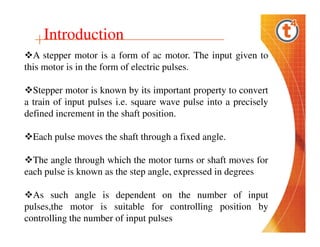
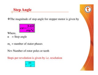
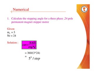
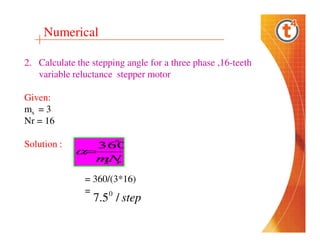
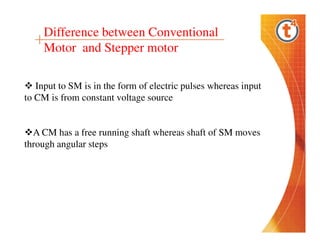
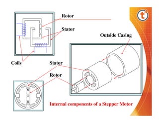
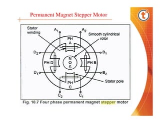
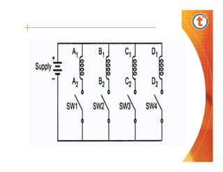
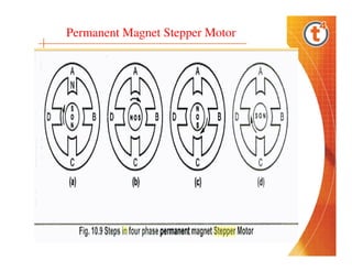
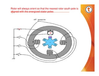
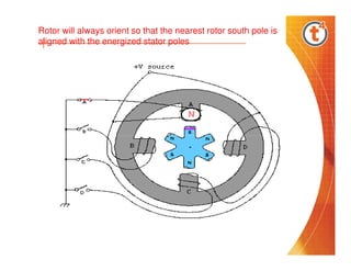
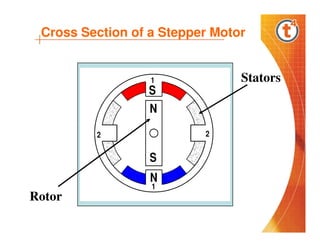
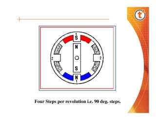
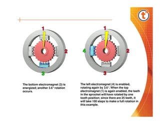
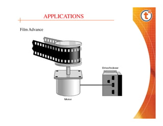
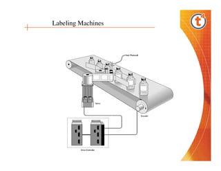
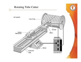

This document discusses stepper motors, which are AC motors that convert input electrical pulses into precise rotational movements. It describes types of stepper motors, such as permanent magnet and variable reluctance, as well as their operation and applications. Additionally, it provides numerical calculations for step angles based on motor specifications.


