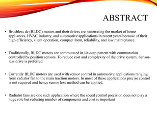
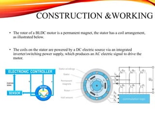
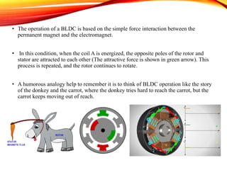
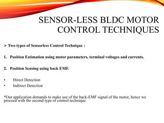
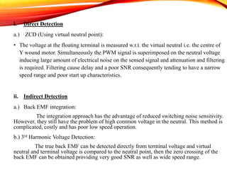
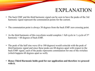
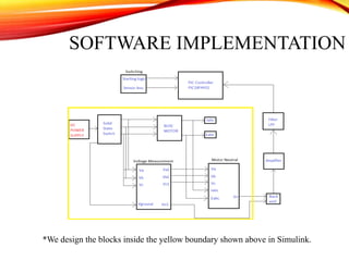
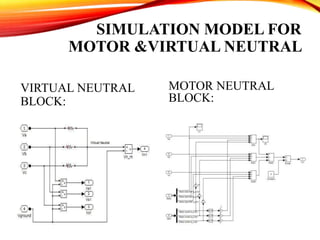
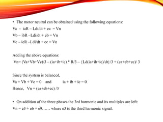
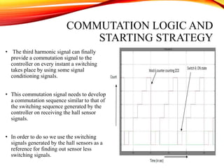
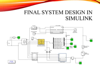
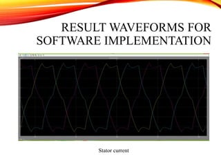
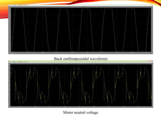
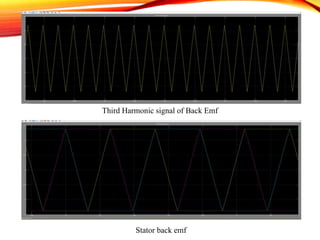
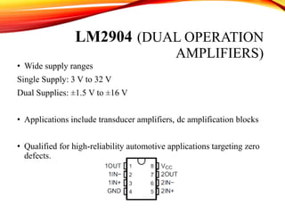
This document summarizes a student project to develop sensorless control of a brushless DC motor using the third harmonic voltage signal method. The objectives are to design a control method, implement it in Simulink, and develop a circuit. BLDC motors are increasingly used due to their efficiency and reliability. Sensorless control can reduce costs by eliminating position sensors. The third harmonic method was chosen because it provides good signal-to-noise ratio and wide speed range. Key steps are extracting the third harmonic from phase voltages, and using its peaks to determine commutation points for switching the motor phases. The project involves modeling the motor and extracting the virtual neutral point in Simulink, and developing the commutation logic and starting strategy.

![4. Sensor less Control of BLDC
Motor Drive Fed by Isolated
DC-DC Converter
Sonia Sunny, Rajesh
Asst. Prof, Department
of EEE, Rajiv Gandhi
Institute of Technology
improved topology of
an isolated DC-DC
converter fed sensor
less BLDC drive
HFT (High Frequency
Transformer) provides
Isolation ensuring safe
operation of the motor
drive.
5. BLDC motor drives using
the unknown input observer
to Sensor less Control
Method for Brushless DC
Motors
Tae-Sung Kim, , Dong-
Myung Lee, and Dong-
Seok Hyun Electrical
Engineering from
Dankook University,
Seoul, Korea,
Line-to line back-
EMF estimation.
detect the rotor position
effectively over a full
speed range, especially at
a low speed range
6. Speed Control of BLDC
Motor Using PID Controller
R.G.Rajesh, C.Balaji
PG Student
[Electronics and
Control], Dept. of ICE,
SRM University,
Chennai
PID controlled
brushless direct
current motor drive
using MATLAB /
SIMULINK
MATLAB/Simulink
environment allows that
many dynamic
characteristics such as
voltage ,rotor speed, phase
current and mechanical
torque can be effectively
Considered.](https://image.slidesharecdn.com/4aecf1f2-bb81-4778-b775-ab74280c0eee-161129033945/85/Final_Presentation-7-320.jpg)
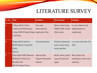
![REFERENCES
[1] Speed Control of BLDC Motor Using PID Controller,” International Journal of Advanced Research in
Electrical, Electronics and Instrumentation Engineering Vol. 3, Issue 4, April 2014”
[2] A New Approach to Sensor-Less Control Method for Brushless DC Motors,” International Journal of
Control, Automation, and Systems, vol. 6, no. 4, pp. 477-487, August 2014”
[3] PWM controlled BLDC Motor, ”International Journal of Scientific and Research Publications, Volume 3,
Issue 4, April 2013 1 ISSN 2250-3153”
[4] Sonia Sunny, Rajesh K, “Sensor-Less Control of BLDC Motor Drive Fed by Isolated DC-DC Converter”,
IJAREEIE (International Journal of Advanced Research in Electrical, Electronics and Instrumentation
Engineering) Vol. 2, Special Issue 1, December 2013
[5] Tae-Sung Kim, Dong-Myung Lee, and Dong-Seok Hyun, “BLDC motor drives using the Line-to line back-
EMF estimation” , International Journal of Control, Automation, and Systems, vol. 6, no. 4, pp. 477-487, August
2008
[6] J. Shao, D. Nolan, M. Teissier, and D. Swanson, “A Novel microcontroller based sensor less brushless DC
(BLDC) motor drive for automotive fuel pumps,” IEEE Trans. Ind. Appl., vol. 39, no. 6, pp. 1734–1740, Nov.
/Dec. 2003.
[7] Charlie Elliott Smart Power Solutions, and Steve Bowling Microchip Technology Inc, “Sensor-less BLDC
control using dsPIC30F” Microchip application note AN901 Sept. 2012.](https://image.slidesharecdn.com/4aecf1f2-bb81-4778-b775-ab74280c0eee-161129033945/85/Final_Presentation-46-320.jpg)