Download to read offline
![International Research Journal of Engineering and Technology (IRJET) e-ISSN: 2395-0056
Volume: 05 Issue: 09 | Sep 2018 www.irjet.net p-ISSN: 2395-0072
© 2019, IRJET | Impact Factor value: 7.211 | ISO 9001:2008 Certified Journal | Page 7055
assumption for simplification. 1. The motor is not
saturated. 2. Stator resistances of all the windings are
equal, and self- and mutual inductances are constant. 3.
Power semiconductor devices in the inverter are ideal. 4.
Iron losses are negligible.
3.PROBLEM RELATED TO SPEED CONTROL OF
BRUSHLESS D.C. MOTOR DRIVE USING SENSORS.
1. Low-cost Hall-effect sensors are usually used. 2.
Electromagnetic variable reluctance (VR) sensors 3.
Accelerometers have been extensively applied to
measure motor position and speed. Hall-effect sensors
These kinds of devices are based on Hall-effect theory,
which states that if an electric current- carrying
conductor is kept in a magnetic field, the magnetic field
exerts a transverse force on the moving charge carriers
that tends to push them to one side of the conductor. A
build-up of charge at the sides of the conductors will
balance this magnetic influence producing a measurable
voltage between the two sides of the conductor.
.
DC MOTOR
To rotate the BLDC motor the stator windings should be
energized in a sequence. It is important to know the
rotor position in order to understand which winding will
be energized following the energizing sequence. Rotor
position is sensed using Hall-effect sensors embedded
into the stator .
The connecting principle between the brushless motor
and this sensor is reminiscent of the miniaturized
magnetic angular encoder based on 3-D Hall sensors. A
permanent magnet is fixed at the end of a rotary shaft
and the magnetic sensor is placed below, and the magnet
creates a magnetic field parallel to the sensor surface.
This surface corresponds to the sensitive directions of
the magnetic sensor. Three-phase brushless motors need
three signals with a phase shift of 120° for control, so a
closed-loop regulation may be used to improve the
motor performance
4. PROBLEMS OCCUR IN SELECTING THE VALUE OF PI
CONTROLLER GAIN SPEED CONTROLLER
The rotor rotation of the BLDC motor, while the motor
speed depends only on the amplitude of the applied
voltage. The required speed is controlled using a speed
controller. The speed controller is implemented as a
conventional PI controller.
4.1PI controller and BLDC
S2+ 2ζωn + ωn2 = 0 (second order system
characteristics equation)
T(s) = (Kp S + Ki ) /[J(s2 + (B + Kp/J)S + Ki /J)] .
T(s) = G(s).H(s) = ( 𝒌𝒑 𝑺+𝒌𝒊𝑺).
(𝟏𝑱𝑺+𝑩) = 𝐊𝐩 𝐒+𝐊𝐢𝐒 ( 𝐉𝐒+𝐁 ) = 𝐊𝐩 𝐒+𝐊𝐢𝐉 𝐒𝟐+ 𝐁+𝐊𝐩 𝐉
𝐒+(𝐊𝐢𝐉) ωn= 𝐊𝐢𝐉 2ζωn = 𝐁+𝐊𝐩 𝐉 ζ = 𝐁+𝐊𝐩 𝟐 𝐉 𝐉𝐊𝐢 =
(𝐁+𝐊𝐩 𝟐) 𝟏𝐉.𝐊𝐢
Here, J = Rotor Inertia of BLDC Motor = 0.087 kg.m2 B =
Viscous Friction of BLDC Motor = 0.005 N.m.s
5.PROPORTIONAL INTEGRAL CONTROLLER DESIGN
The model of PI speed controller is given by,
G(s) =Kp+(Ki / s)](https://image.slidesharecdn.com/irjet-v6i3789-190917053856/75/IRJET-Analysis-the-Speed-Manage-of-BLDC-Motor-Drive-using-Sensors-2-2048.jpg)
![International Research Journal of Engineering and Technology (IRJET) e-ISSN: 2395-0056
Volume: 05 Issue: 09 | Sep 2018 www.irjet.net p-ISSN: 2395-0072
© 2019, IRJET | Impact Factor value: 7.211 | ISO 9001:2008 Certified Journal | Page 7056
Where G(S) is the controller transfer function which is
torque to error ratio in s-domain, Kp is the proportional
gain and Ki is the integral gain. The tuning of these
parameters is done using Ziegler Nichols method using
the phase and gain Margin specifications. The
specifications of the drive application are usually
available in terms of percentage overshoot and settling
time. The PI parameters are chosen so as to place the
poles at appropriate locations to get the desired
response. These parameters are obtained using Ziegler
Nichols method which ensures stability. From the
dynamic response obtained by simulation, the
percentages overshoot Mp and settling time ts which are
the measures of Transient behaviors are obtained. The
speed loop of the typical BLDC motor under no load
condition. The closed loop transfer function of the
system is given by
T(s) = (Kp S + Ki)/ [J (s2 + (B + Kp/J) S + (Ki /J )]
5.1 METHODOLOGY MATHEMATICAL MODELING OF
THE AC MACHINE
The electrical system dynamics may be described by two
voltage equation:
ν1 = r1 i1 + pλ1
ν2 = r2 i2 + pλ2
Where p is the Heaviside notation for the time
differentiation operator d/dt. Assume that the stator flux
linkages are linearly related to the currents, the flux
linkage λ1 and λ2 may be expressed:
λ1 = L11 i1 + L12 i2 + λpm1
λ2 = L21 i1 + L22 i2 + λpm2
The stator windings are symmetric, i.e. they have the
same total self-inductance, resistance, and number of
turns. Since the self –inductance is the same for
windings, L11 and L22 will denote as Lss. Since the
stator windings are tightly wound on highly permeable
stator steel, the numerical value of the mutual
inductance is nearly equal to the total self-inductance.
However, since the magnetic axes are in opposite
directions for positive current in each winding, the
mutual inductance is negative. A minus sign and the
symbol Lm will replace L12 and L21 . The symmetry and
configuration of the windings indicate that both have the
same permanent–magnet component of flux linkage but
with opposite signs. The symbol λm will be used for the
permanent-magnet flux linkage term.
ν1 = rsi1 + Lss p i1 -Lm p i2 + pλm
ν2 = rsi2 - Lss p i1 + Lm p i2 – pλm
pλmcan be expressed as ωr(dλm/dθr) and represents
the no-load or back emf of the motor. The induced
voltage due to armature reaction are related to the terms
containing Lss and Lm which, when added to the back
emf , establish the total induced voltages in the stator
windings. For the mechanical system, the torque
developed by the electromagnetic system counters the
inertial acceleration torque, the torques due to windage
and friction ( modeled as being proportional to rotor
velocity), and the load torque , i.e.
Te=Jpωr + B ωr +TL
The interaction of currents in the stator electrical
system with the magnetic field of the rotor permanent
magnets creates an electromagnetic torque, Te. The
electromagnetic torque may be established by
expressing the partial derivative of the co energy w.r.t.
position. The resulting expression for the
electromagnetic torque is:
Te = (I1 –I2) 𝑑𝜆𝑚𝑑𝜃𝑟 - 𝑑𝑊𝑝𝑚𝑑𝜃𝑟
Where Wpm represented the coupling field energy due
to the permanent magnets. Total derivatives because λm
and Wpm are functions only of θr. The first term on the
right-hand side of equation represents the
electromagnetic torque produced by the interaction of
electric current in the stator windings with the magnetic
field of the rotor permanent magnets.
The second term represents a torque due to the
attraction between the rotor permanent magnet and the
stator steel and acts to drive the rotor to a position
having the lowest permanent magnet component of
coupling field energy. This torque hereafter referred to
as the cogging torque Tec, ensures that the rotor position
of the unexcited motor is such that an electromagnetic
torque sufficient for starting is developed when the
stator windings are suddenly energized. The cogging
torque does not depend upon the stator currents and is a
function only of θr. It is incorporated in the state model
as a position dependent load torque.
The cogging torque is assumed to very sinusoidalw.r.t.
Rotor position. The peak value of the cogging torque and
the rotor position at which the cogging torque is
maximum were measured experimentally for the given
four-pole motor. The variation of cogging torque w.r.t.
rotor position is not exactly sinusoidal; the only time that
the cogging torque is important is during start-up.
In practically, the cogging torques acts to drive the rotor
of an unexcited machine to a position such that when the
source voltage is suddenly applied, the resulting
electromagnetic torque accelerates the rotor in the
proper direction. After some algebraic manipulation
may be expressed in state-model from as:](https://image.slidesharecdn.com/irjet-v6i3789-190917053856/75/IRJET-Analysis-the-Speed-Manage-of-BLDC-Motor-Drive-using-Sensors-3-2048.jpg)
![International Research Journal of Engineering and Technology (IRJET) e-ISSN: 2395-0056
Volume: 05 Issue: 09 | Sep 2018 www.irjet.net p-ISSN: 2395-0072
© 2019, IRJET | Impact Factor value: 7.211 | ISO 9001:2008 Certified Journal | Page 7057
pi1 = 1Lss (1−k2) [(ν1 -rs ) + k( ν2 - rest i2) – (1-k)
ωrdλmdθr ]
PERFORMANCE OF BLDC MOTOR The actual shaft
output torque is:
Tload = Tem – Tlosses
Where Tlosses is the total losses due to friction, windage,
and iron losses. Dropping the amplitude signs, we have
Tem = 𝑚𝑝2 גm I Speed-torque curve:- The voltage
equation can be simplified as V = E + IR Substituting the
relations of E -ωr and T-I, we obtain.
ν = 𝑃2ωrλm+ 2𝑅𝑚𝑝𝜆𝑚 Tem
ωr = 2𝜈𝑝𝜆𝑚 - 4𝑅𝑚 𝑝𝜆𝑚 2 Tem
6.MECHANICAL INPUT
Allows you to select either the load torque or the motor
speed as mechanical input. Note that if you select and
apply a load torque, you will obtain as output the motor
speed according to the following differential equation
that describes the mechanical system dynamics: Te=
J𝑑𝑑𝑡ωr + F ωr +Tm This mechanical system is included
in the motor model. However if you select the motor
speed as mechanical input then you will get the
electromagnetic torque as output, allowing you to
represent externally the mechanical system dynamics.
Note that the internal mechanical system is not used
with this mechanical input selection and the inertia and
viscous friction parameters are not displayed.
6.1Block diagram of BLDC Motor Drive
This circuit uses the AC7 block of SimPower System
library. It models a brushless DC motor drive with a
braking chopper for a 3HP motor. The permanent
magnet synchronous motor (with trapezoidal back-EMF)
is fed by a three phase inverter, which is built using a
Universal Bridge Block. The speed control loop uses a PI
regulator to produce the torque reference for the current
control block.
6.2 Current Controllers
In the BLDC motor drive, duty cycle controlled voltage
PWM technique and hysteresis current control technique
can be regarded as the main current control strategies.
In this thesis bipolar hysteresis current control is used
for obtaining the fast dynamic responses during
transient states.
6.3Brushless D.C. Motor Drive (SIMULINK)
Implement brushless DC motor drive using Permanent
Magnet Synchronous Motor (PMSM) with trapezoidal
back electromotive force (BEMF).
7.RESULIT
Stator Current of BLDC Motor
This graph represents the stator current ( ia in Amp) vs
time (in sec.) of Brushless Dc Motor. Stator
currentwaveform is not smooth because some
harmonics are present in input.
Rotor Speed of BLDC Motor
This graph represents the rotor speed (in rpm) vs time
(in sec) of BLDC motor.Speed of themotor is varied in
between Rated Speed 78.5 rad/sec. at 0 sec but without
Torque. BLDC Motor is 8poles Motor and frequency is 50
Hz, then
Speed(N) = (120*frequency) / Numbers of poles.
Ѡm = 2π* N
Electromagnetic Torque of BLDC motor
As shown in the following figure, the speed precisely
follows the acceleration ramp. At t = 0.2 s, the nominal
load torque is applied 1.4 Nm to the motor. At t = 1 s, the
speed set point is changed to 0 rpm. The speed increases
to 0rpm. At t = 1.2 s., the mechanical load passes from 0
N.m.](https://image.slidesharecdn.com/irjet-v6i3789-190917053856/75/IRJET-Analysis-the-Speed-Manage-of-BLDC-Motor-Drive-using-Sensors-4-2048.jpg)
![International Research Journal of Engineering and Technology (IRJET) e-ISSN: 2395-0056
Volume: 05 Issue: 09 | Sep 2018 www.irjet.net p-ISSN: 2395-0072
© 2019, IRJET | Impact Factor value: 7.211 | ISO 9001:2008 Certified Journal | Page 7058
DC Bus voltage of BLDC Motor
This graph represents the variation of dc bus voltage (in
volts) with respect to time. This D.C. bus voltage
isobtained from Three- phase rectifier circuits.
8.CONCLUSION
In this paper a mathematical model of brushless DC
motor is developed. The simulation of the brushless
DC motor was done using the software package
MATLAB/SIMULINK. a review of position control using
Hall sensor methods for BLDC motors has been
presented.It is obvious that the control for BLDC motors
using position sensors, such as shaft encoders, resolvers
or Halleffect probes, can be improved by means of the
elimination of these sensors to further reduce cost and
increase reliability. we have done result analysis and
found results in different load conditions. We have also
analyzed the steady state condition and transient
condition. The steady state condition was found to be
very close to the transient condition.
REFERENCE
1.J.S. Mayer, student or O. Wasynezuk, senior member.
Analysis and modelling of a single-phase brushless D.C.
motor drive system , IEEE Transactions on Energy
Conversion, vol. 4, No. 3, September 1989.
2. P. Pillay and R. Krishnan, “Modeling, simulation, and
analysis of permanent-magnet motor drives, part II: the
brushless DC motor drive,” IEEE Trans. on Industry
Applications, vol. 25, no. 2, pp. 274–279, March/April
1989.
3.R. Carlson, M. Lajoie-Mazenc, and C. dos S. Fagundes,
“Analysis of torque ripple due to phase commutation in
brushless DC machines,” IEEE Trans. on Industry
Applications, vol. 28, no. 3, pp. 632–638, May/June 1992.
[11] P. D. Evans and D. Brown, “Simulation of brushless
DC drives,” Proc. of the IEEE, vol. 137, no. 5, pp. 299–308,
September 1990.
4. S. K. Safi, P. P. Acarnley, and A. G. Jack, “Analysis and
simulation of the high-speed torque performance of
brushless DC motor drives,” Proc. of the IEE, vol. 142, no.
3, pp. 191–200, May 1995.](https://image.slidesharecdn.com/irjet-v6i3789-190917053856/75/IRJET-Analysis-the-Speed-Manage-of-BLDC-Motor-Drive-using-Sensors-5-2048.jpg)

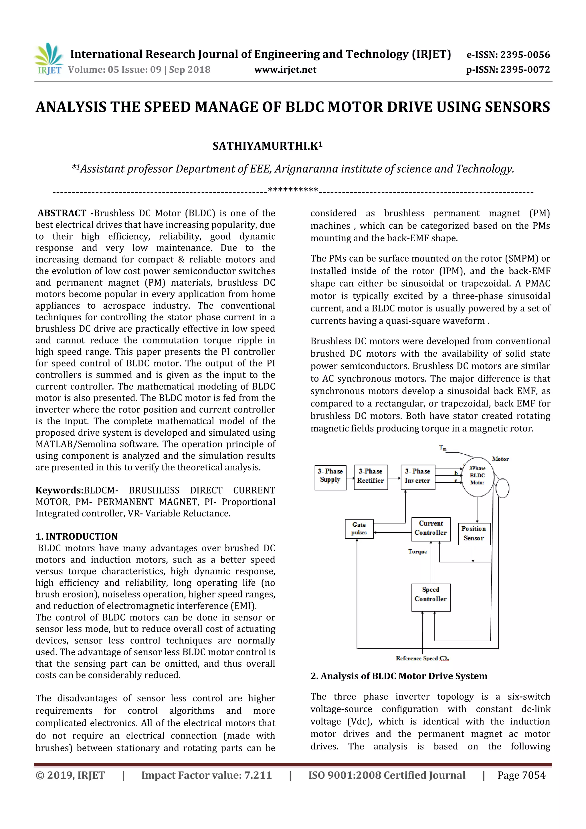
This document analyzes the speed control of a brushless DC motor (BLDC) using sensors. It begins with an introduction to BLDC motors and their advantages over brushed DC motors. It then presents the mathematical modeling of a BLDC motor, including voltage and flux linkage equations. It describes using Hall-effect sensors to sense the rotor position and control the motor. The document discusses using a PI controller for speed control and the challenges in selecting the PI gains. It concludes by presenting the methodology for mathematically modeling the motor, including the electrical and mechanical system dynamics equations.