Downloaded 2,552 times

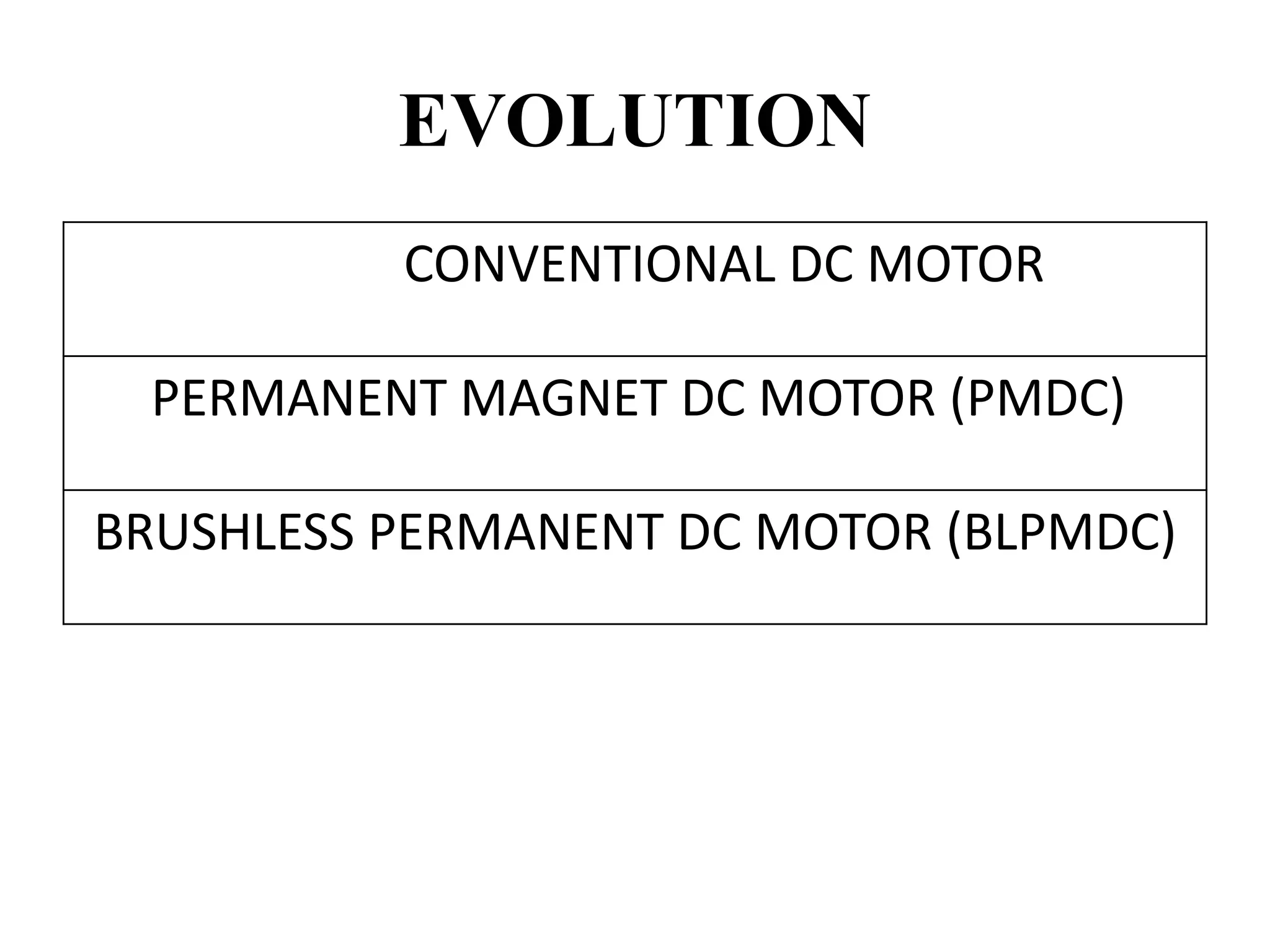
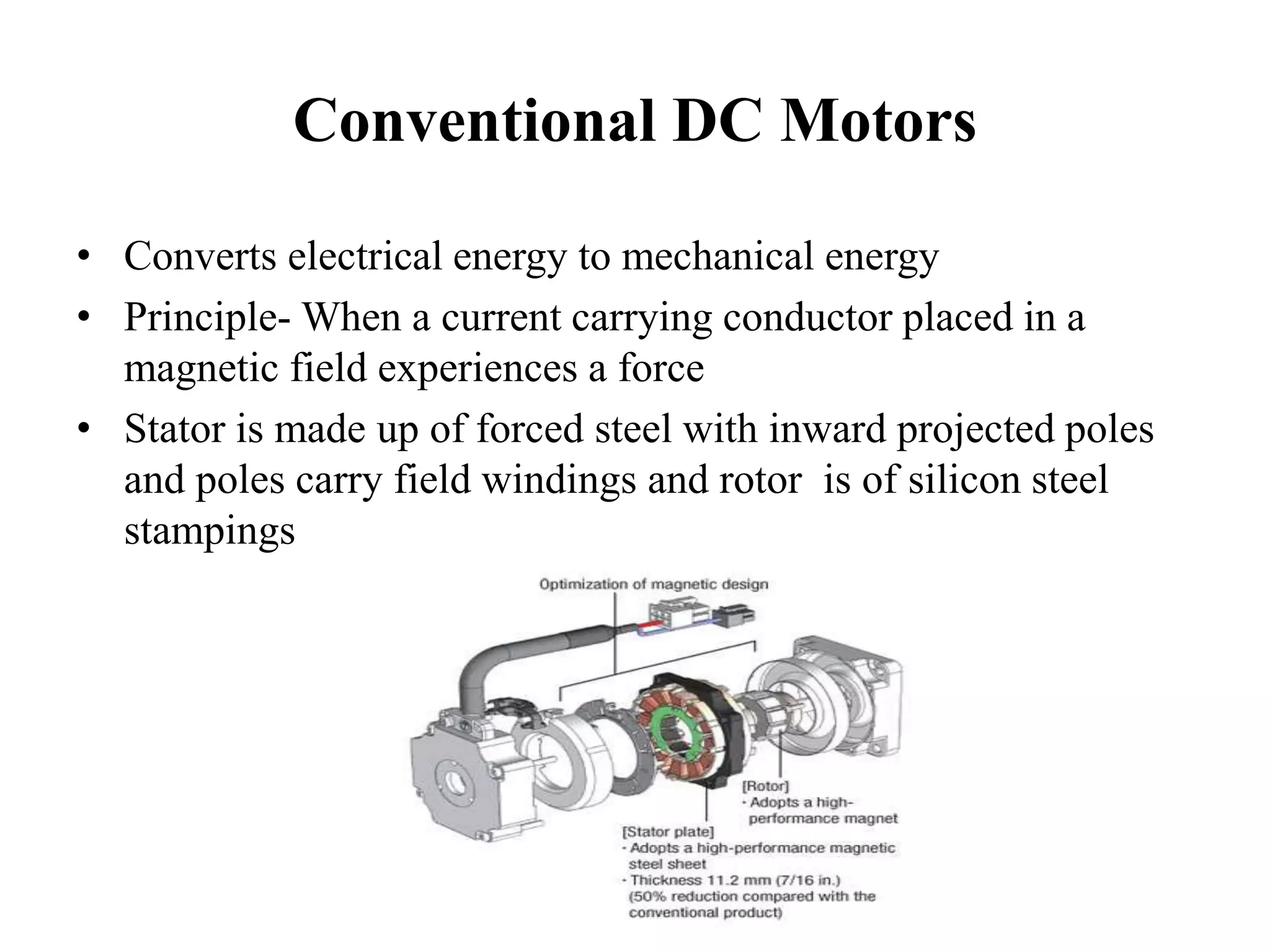
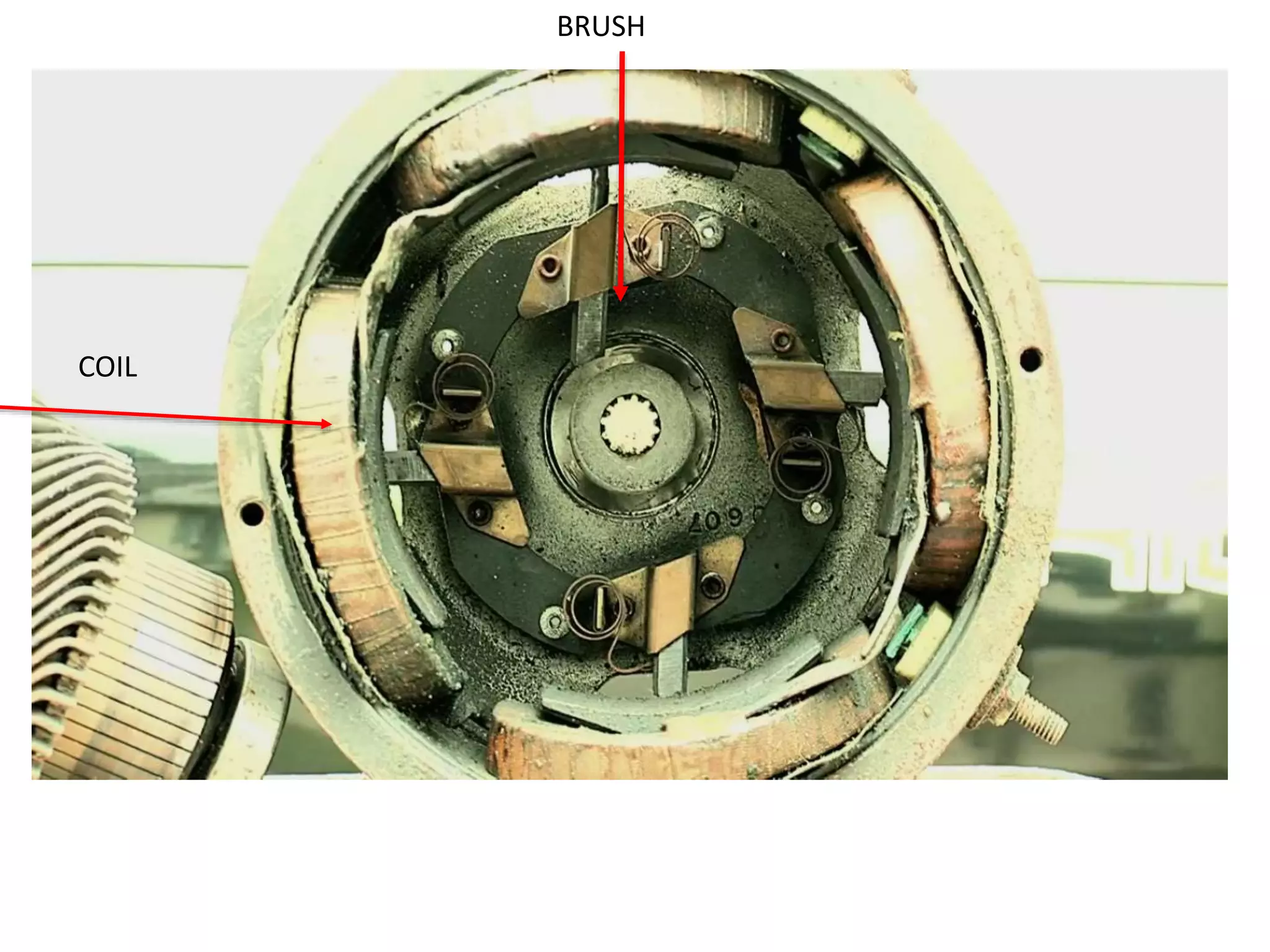


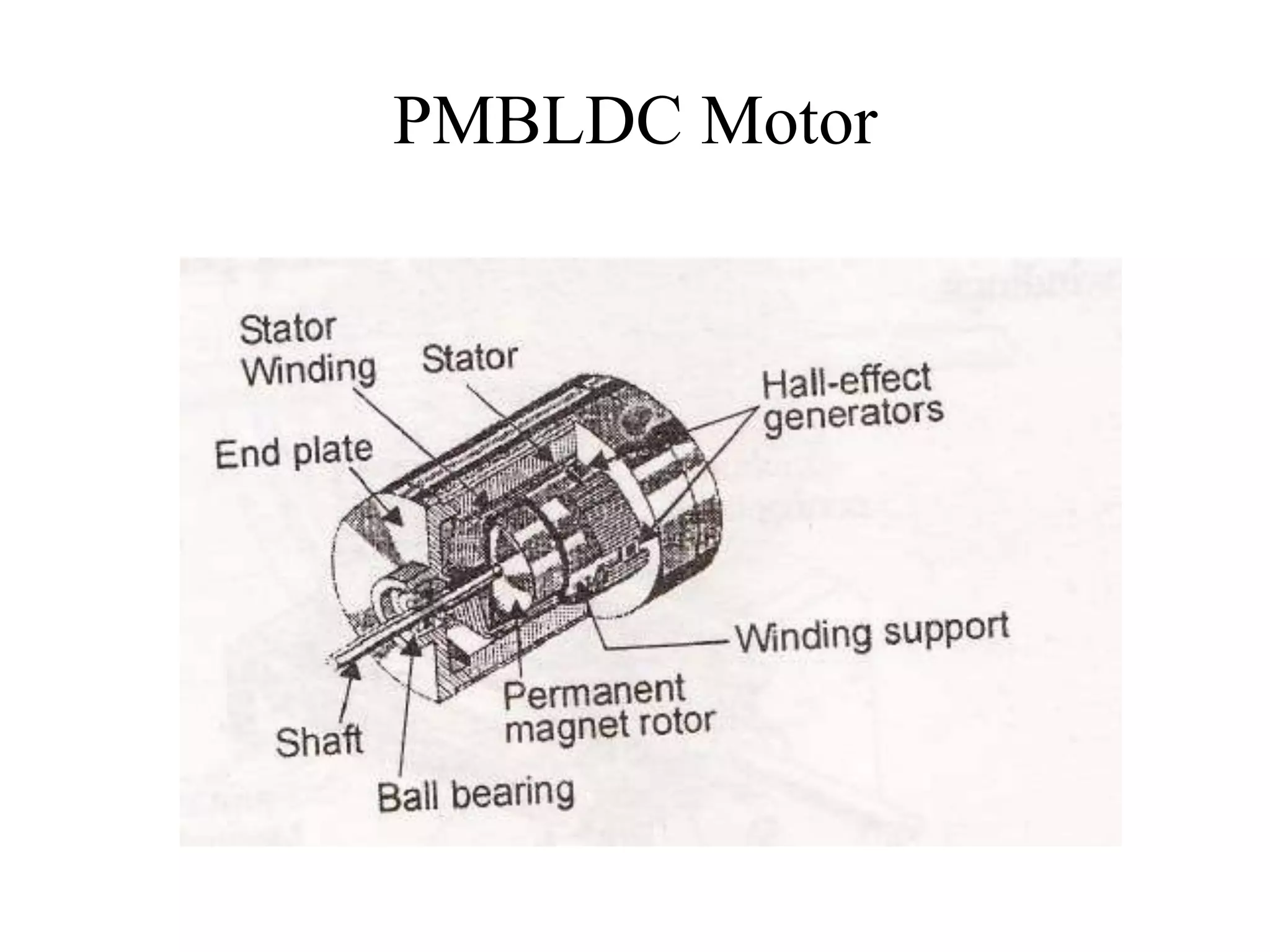

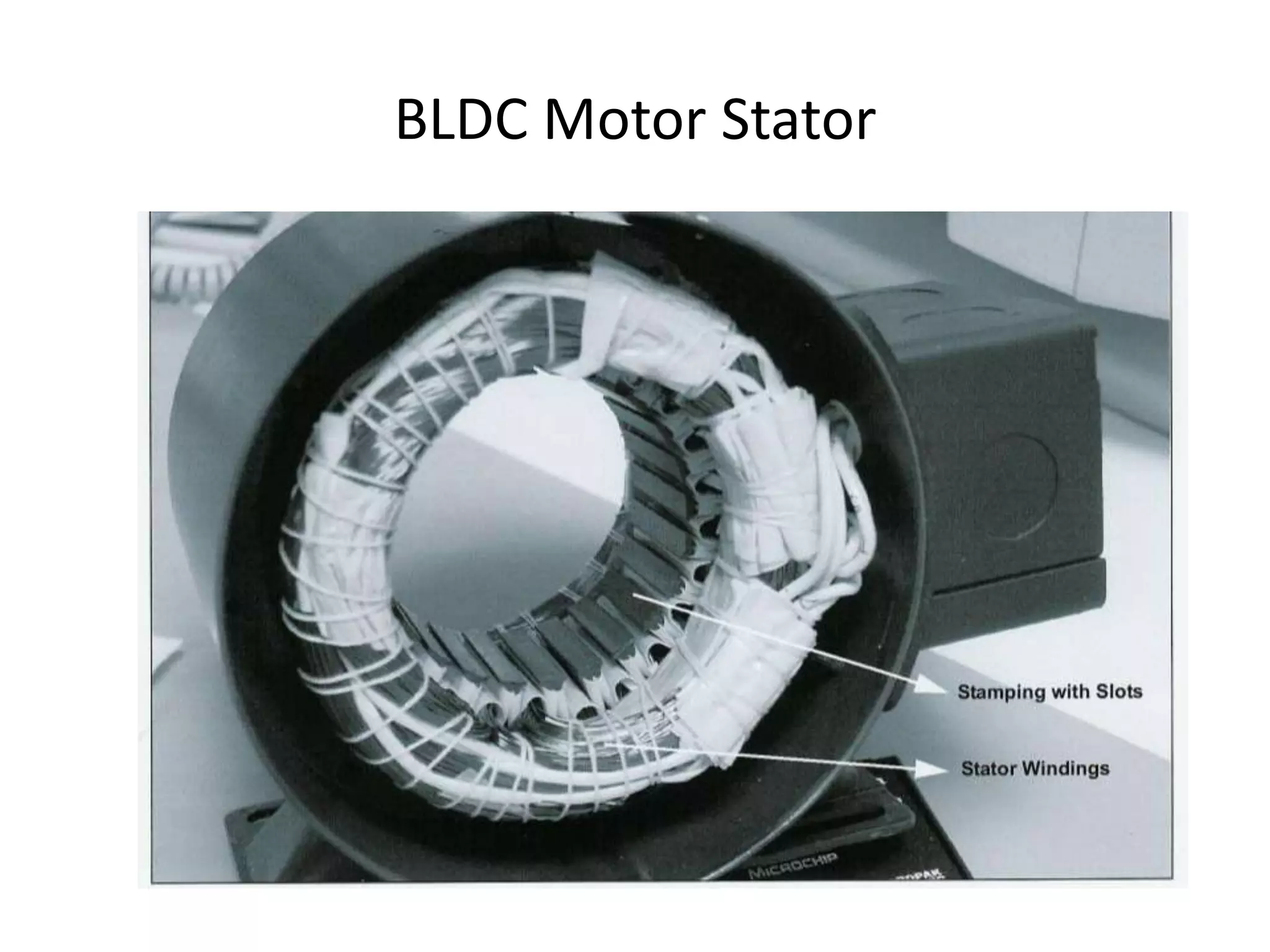

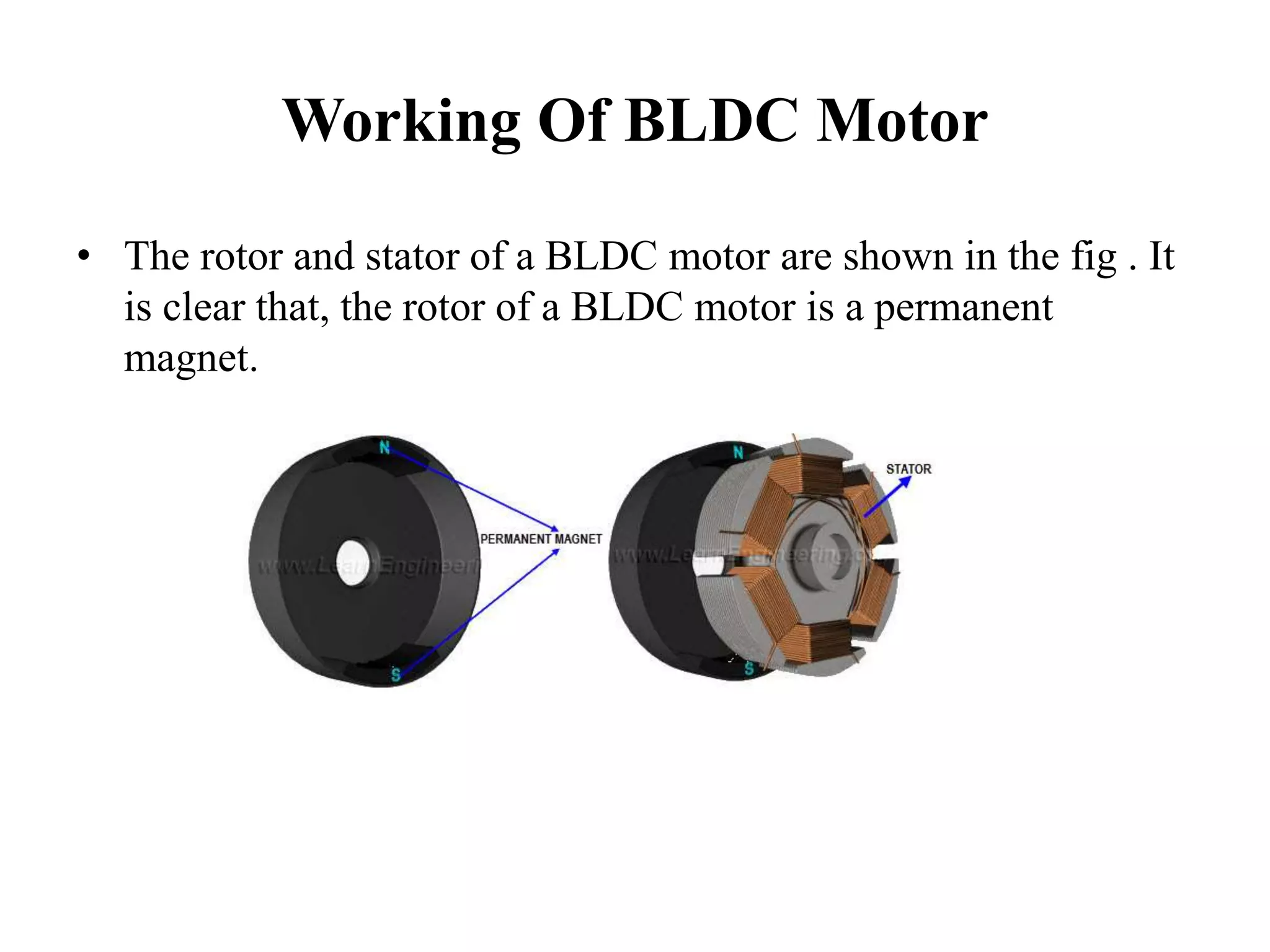

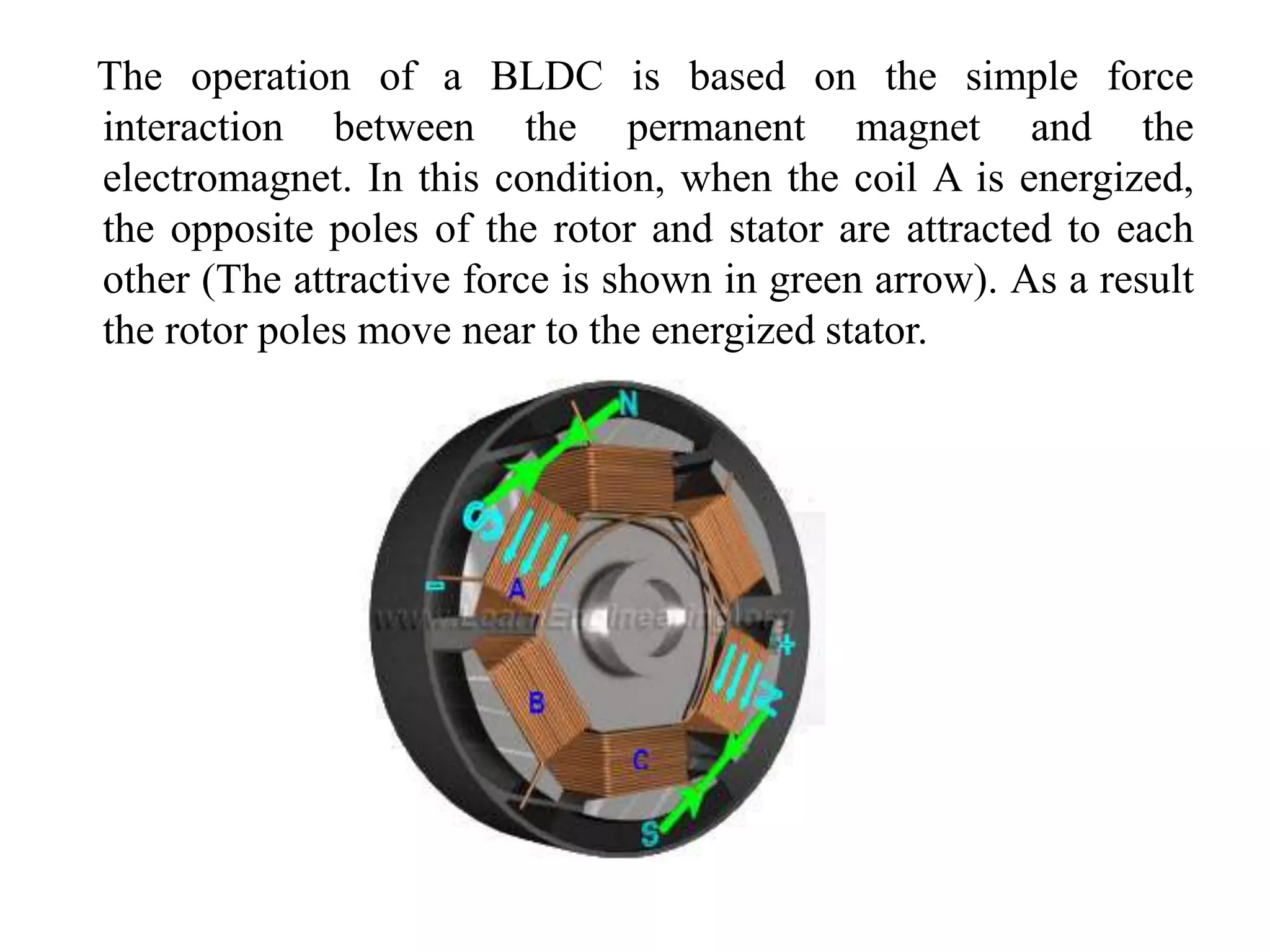


BLDC motors have evolved from conventional DC motors to permanent magnet DC motors to brushless permanent magnet DC motors. A BLDC motor consists of a stator and a rotor, with the rotor containing permanent magnets and the stator containing coil windings. BLDCs improve reliability and efficiency over brushed DC motors by replacing the brush and commutator assembly with electronic commutation, which controls the sequence of energizing the stator windings. This electronic control allows BLDCs to have higher speed and torque characteristics than conventional DC motors.