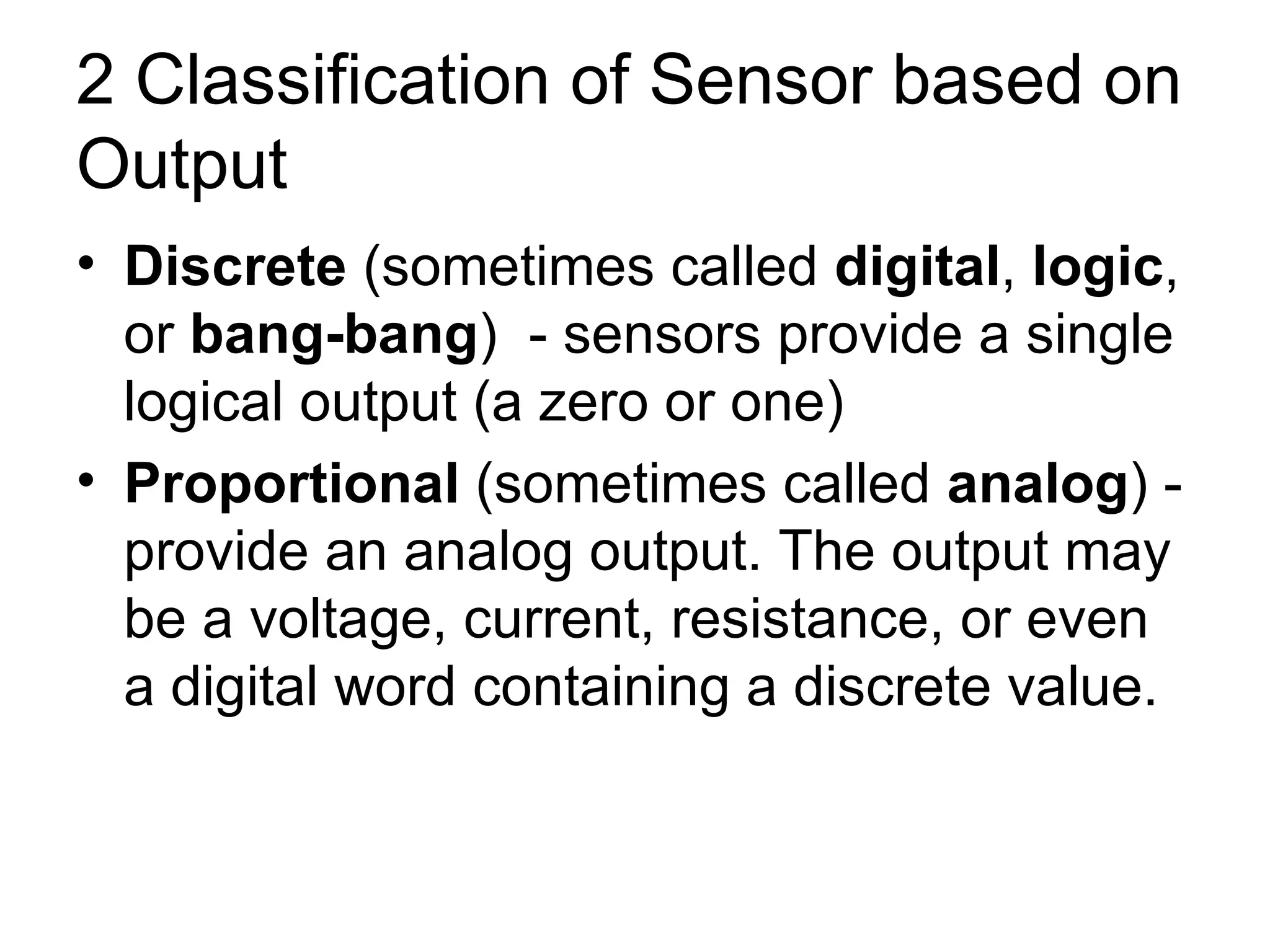
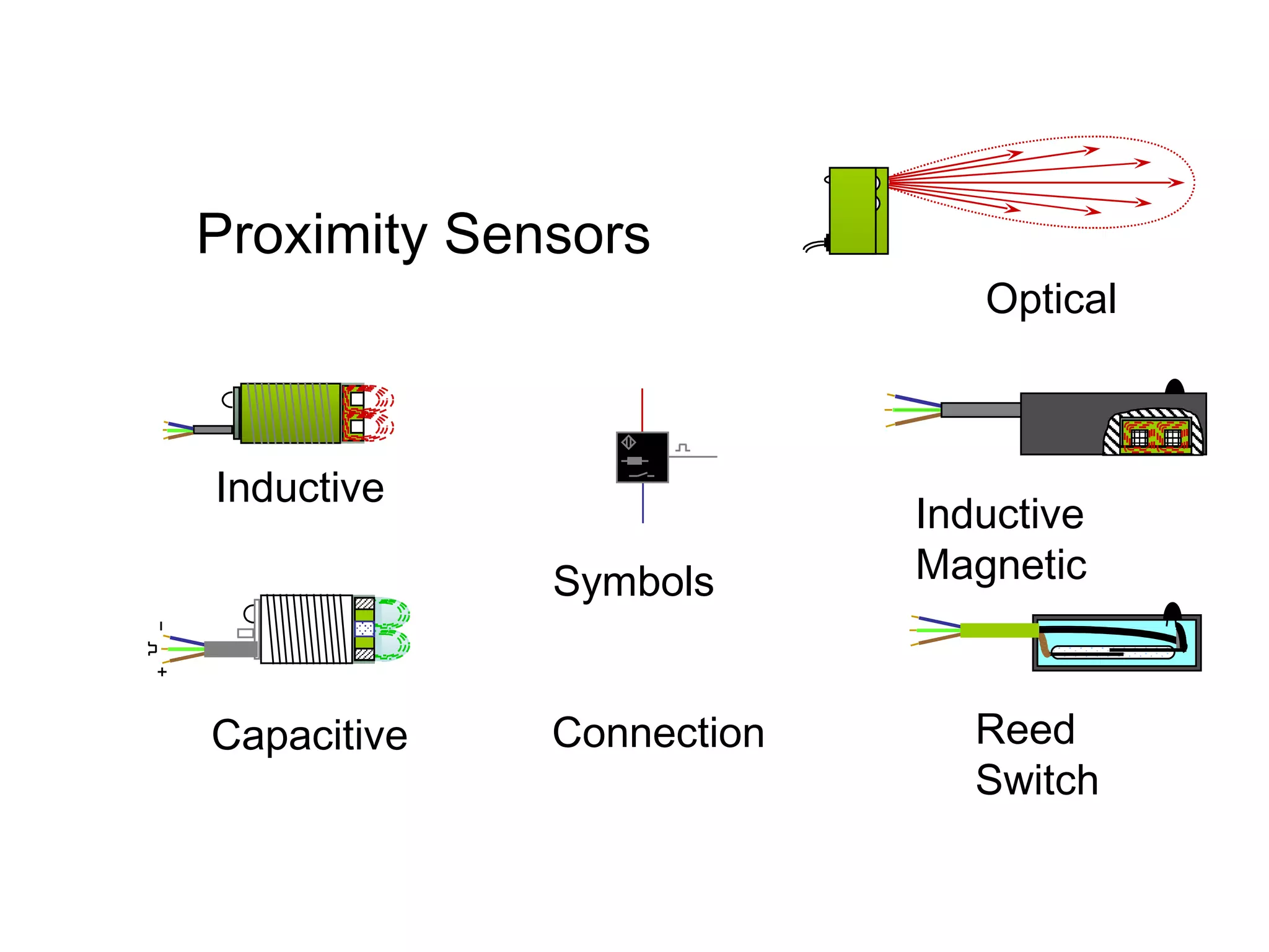
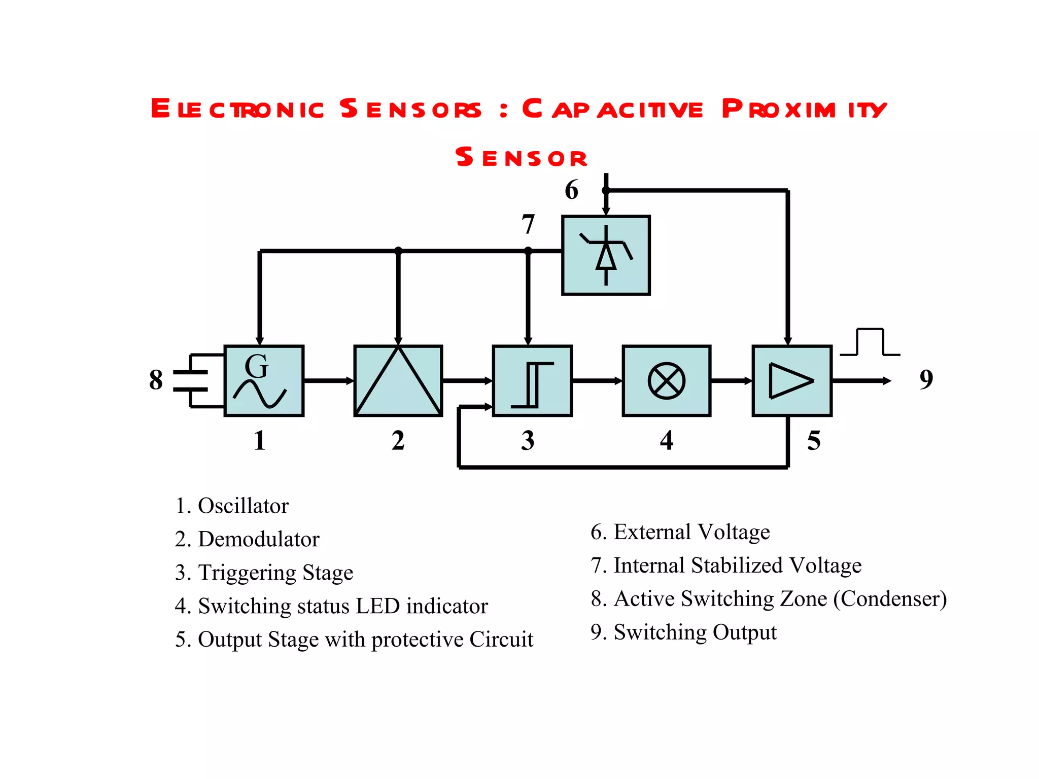
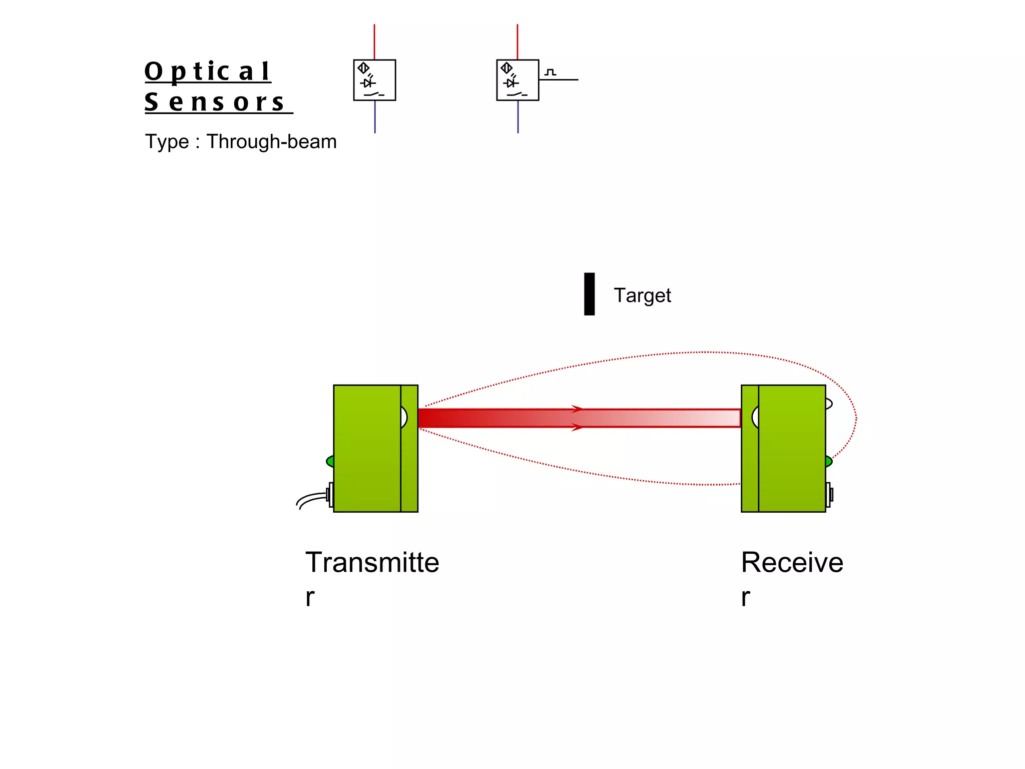
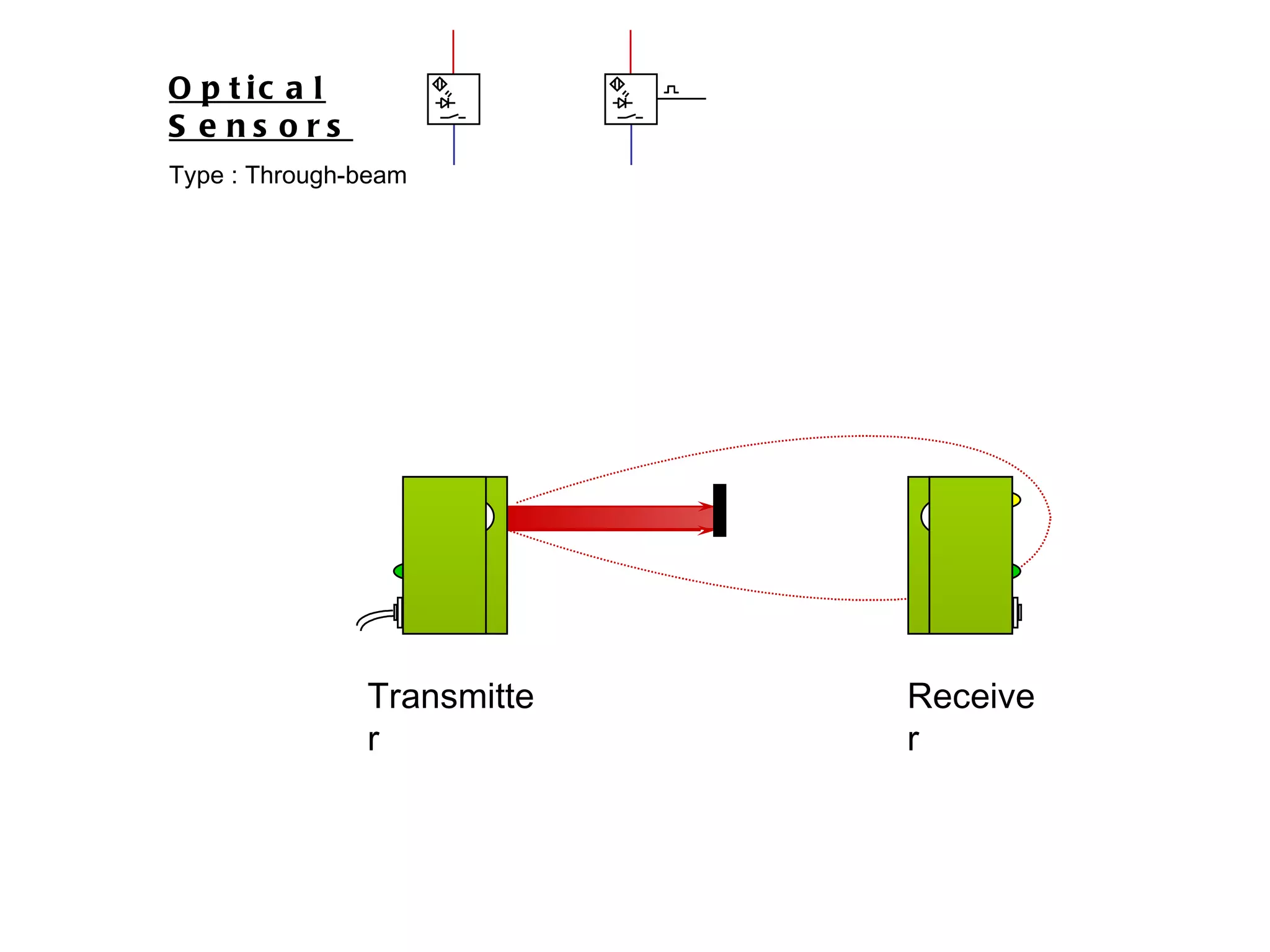
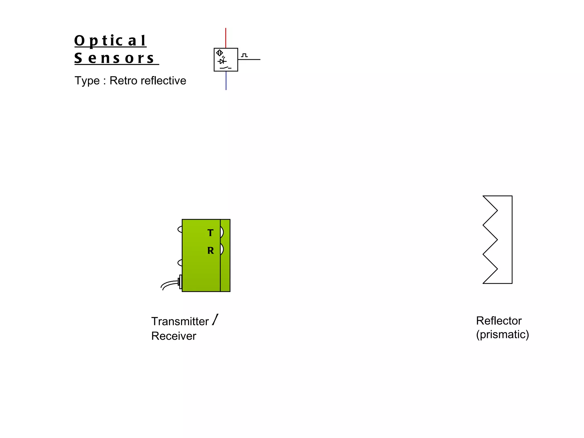
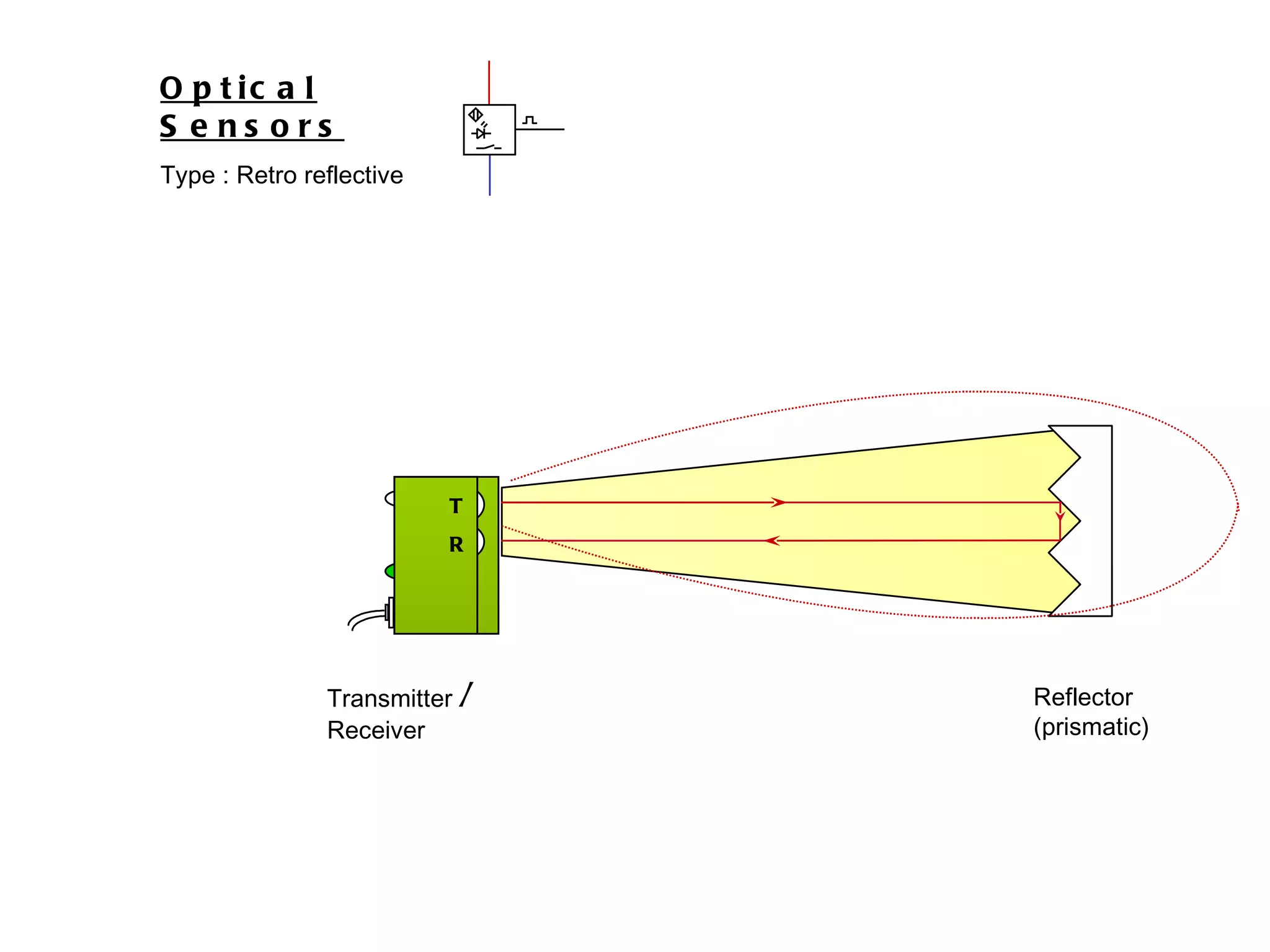
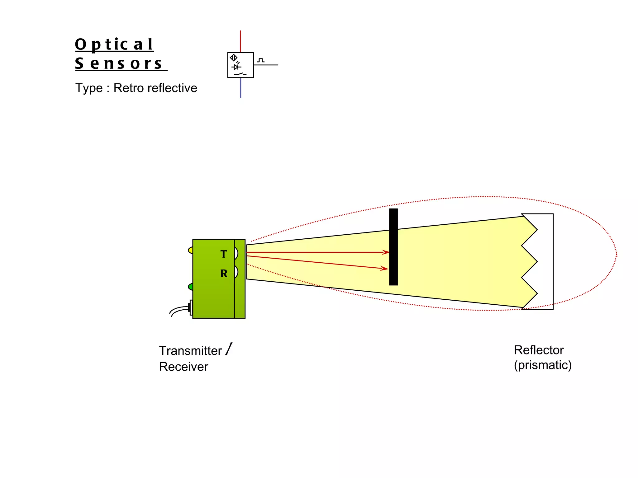
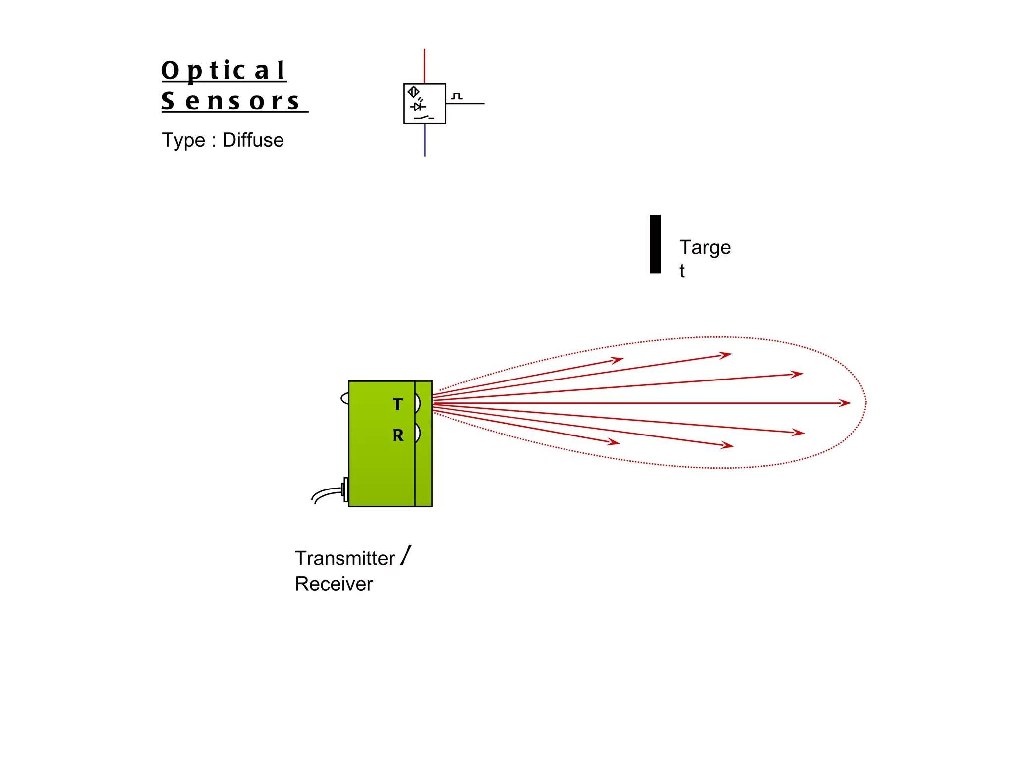
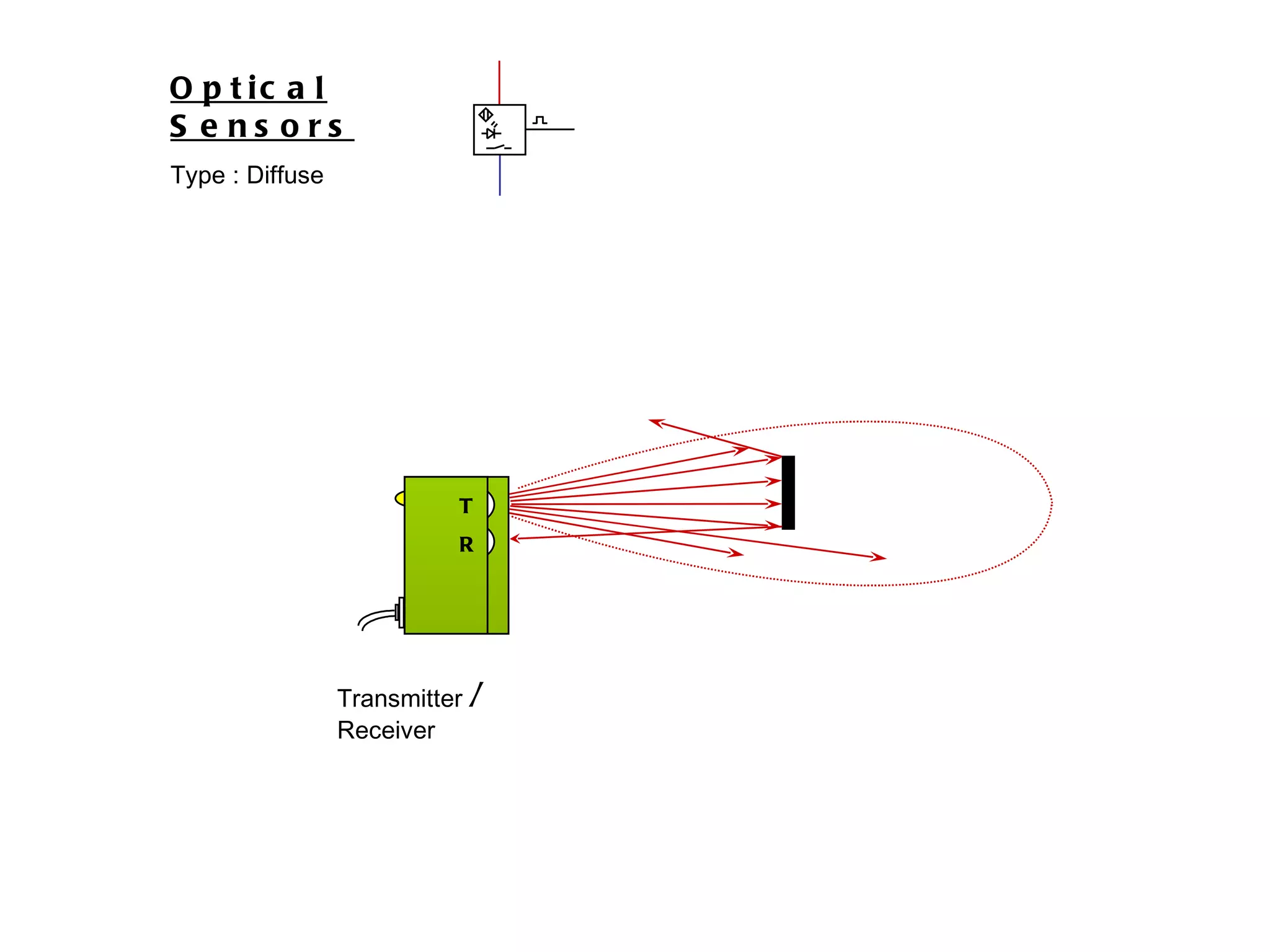
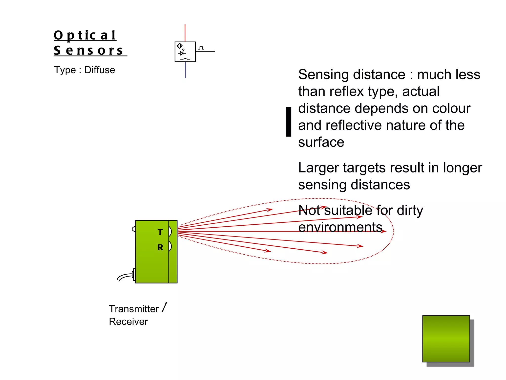
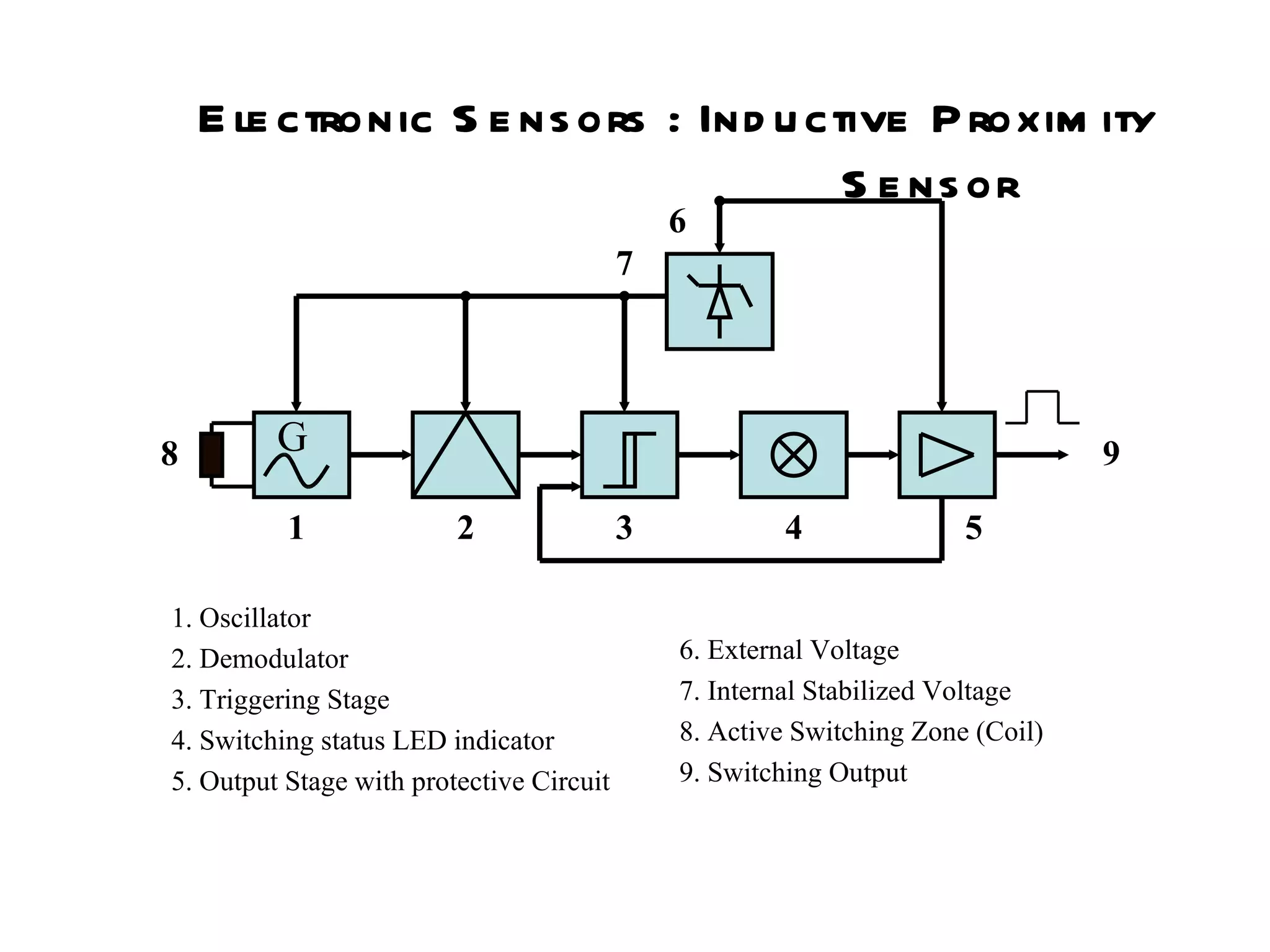
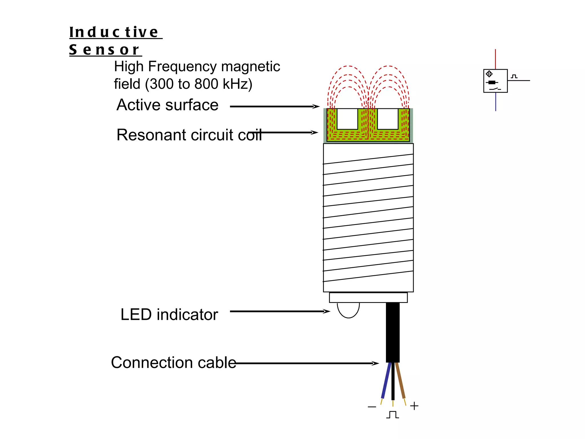
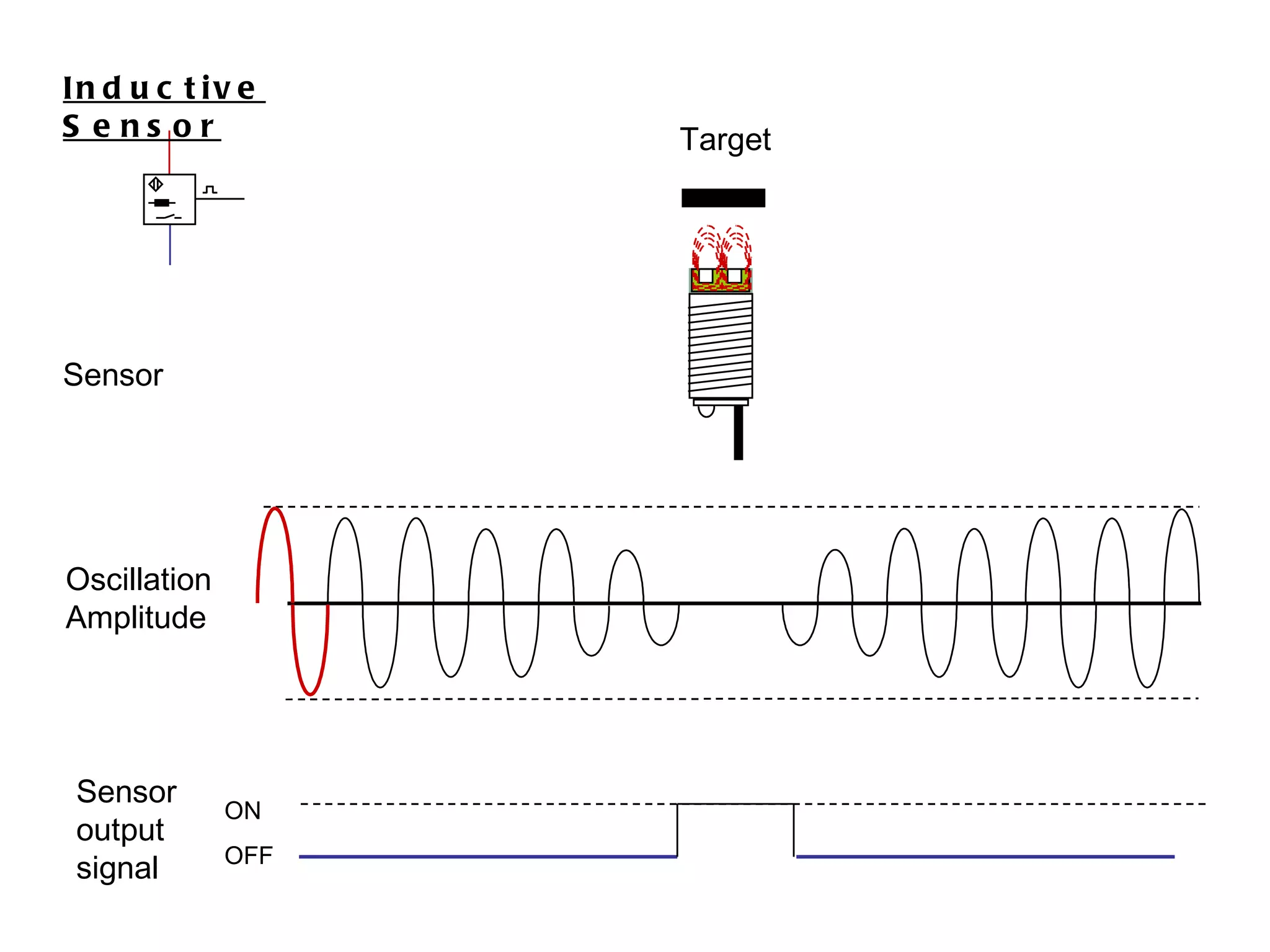
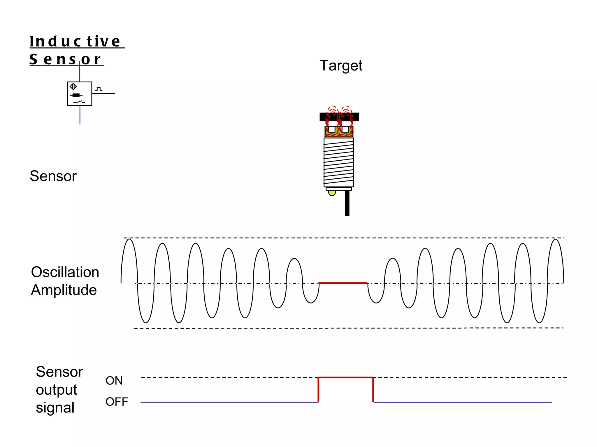
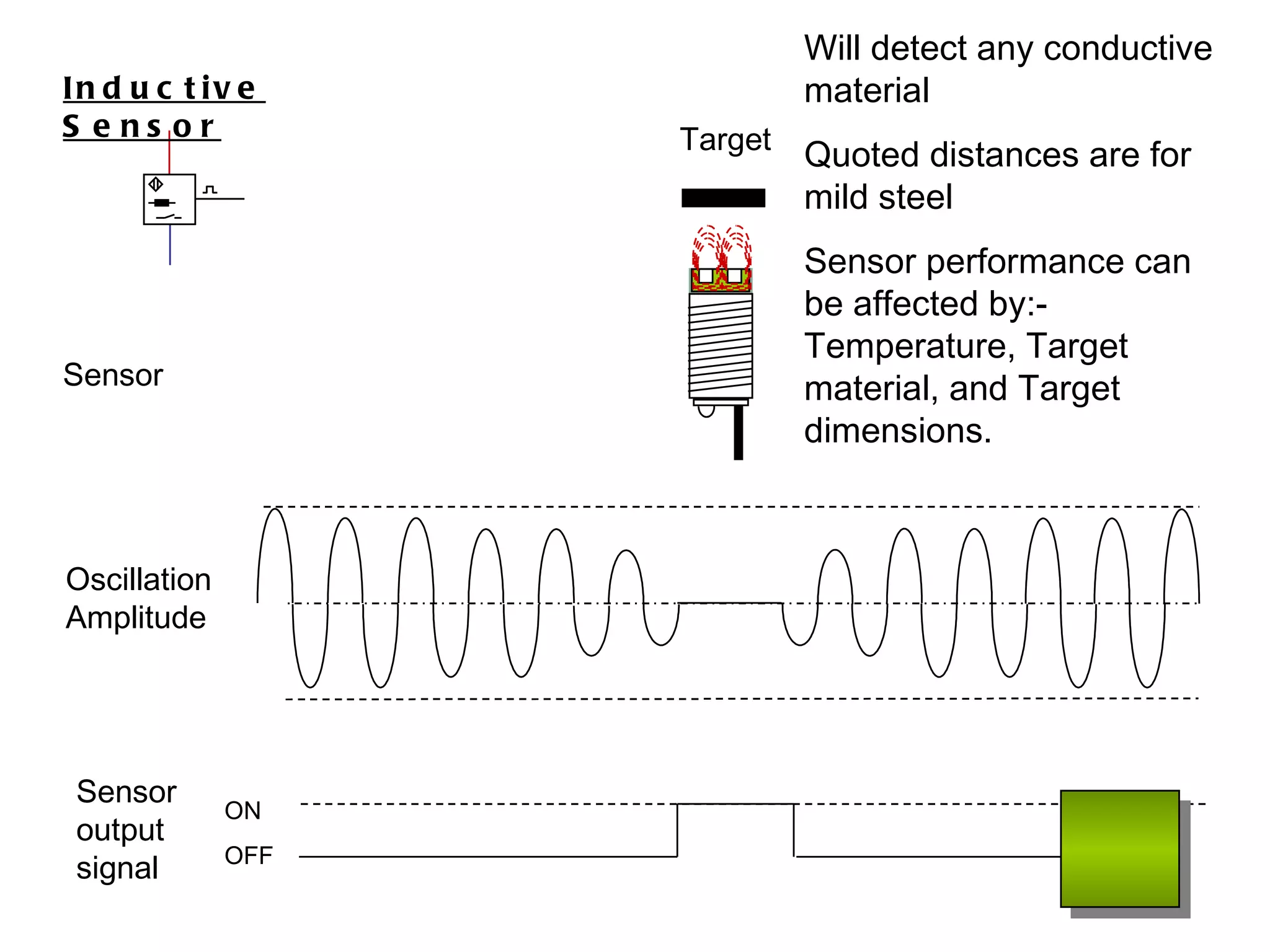
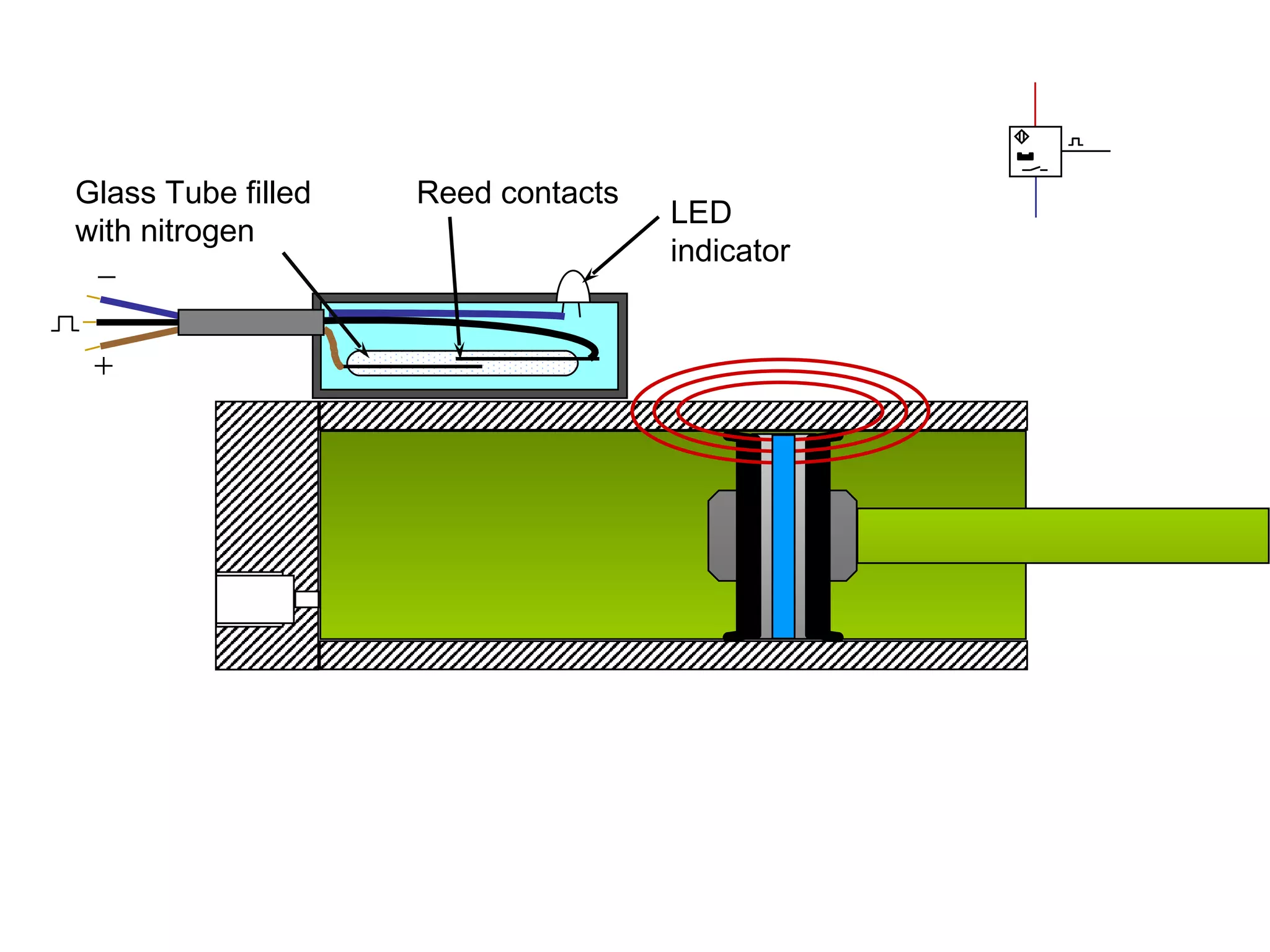
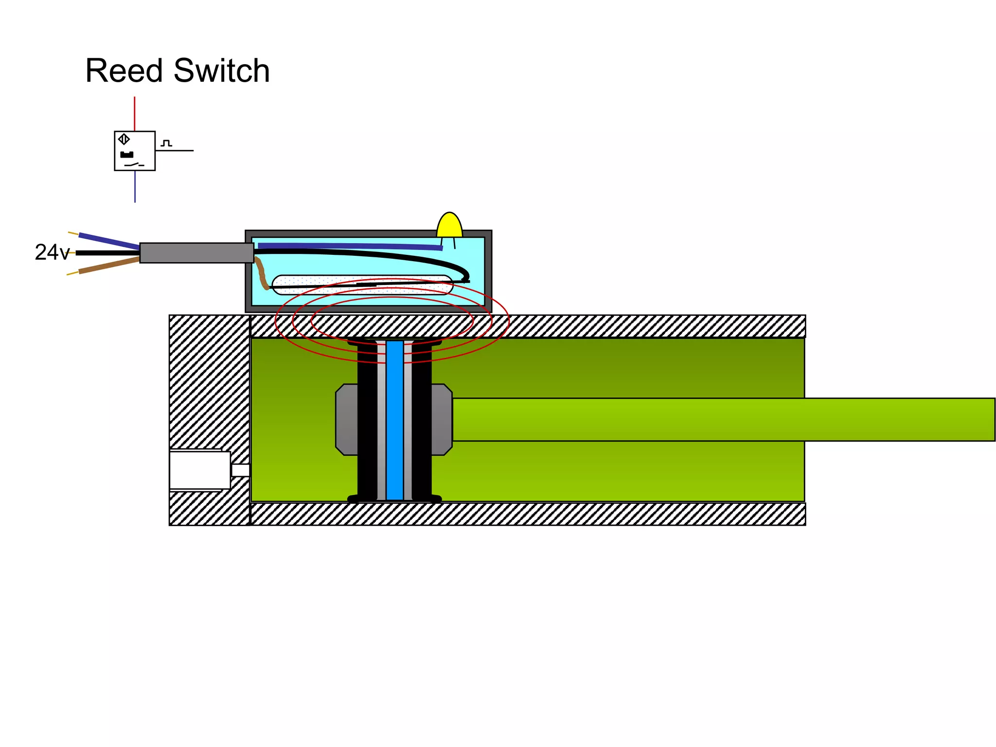
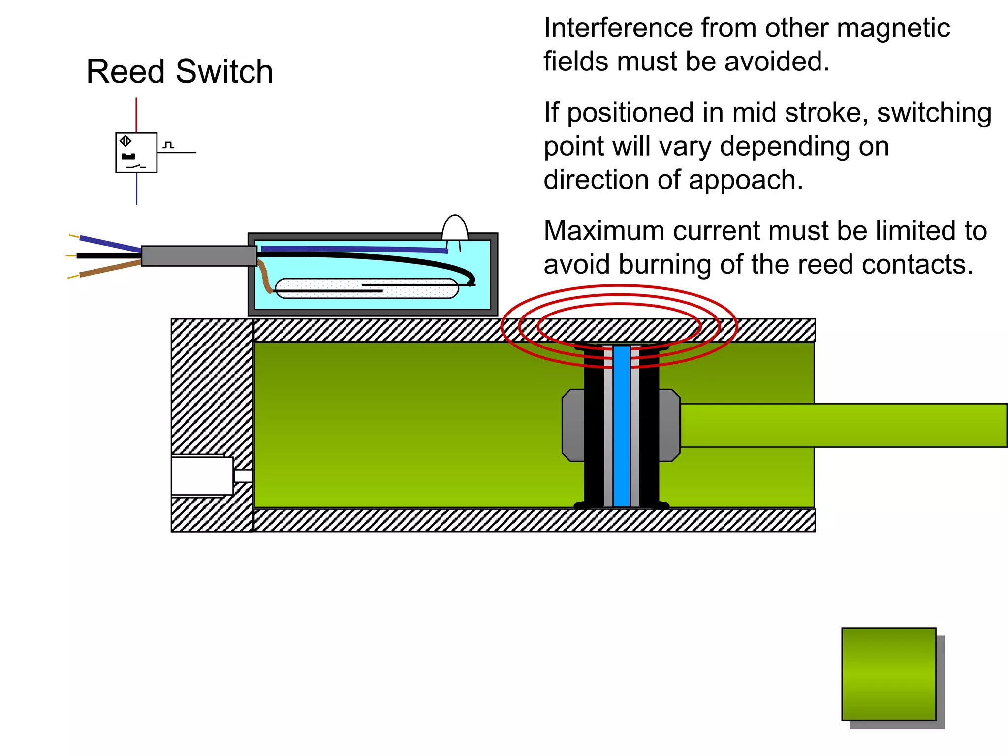
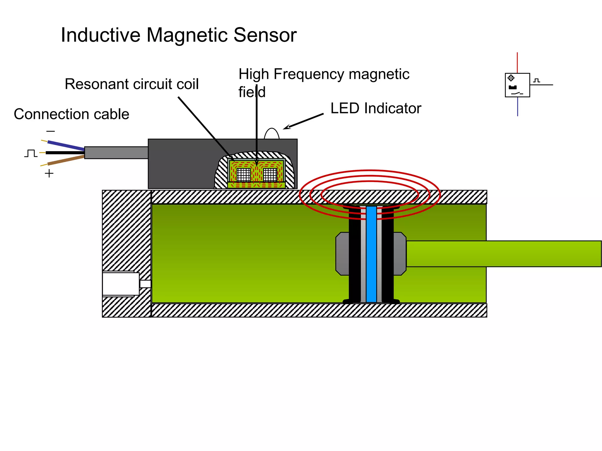
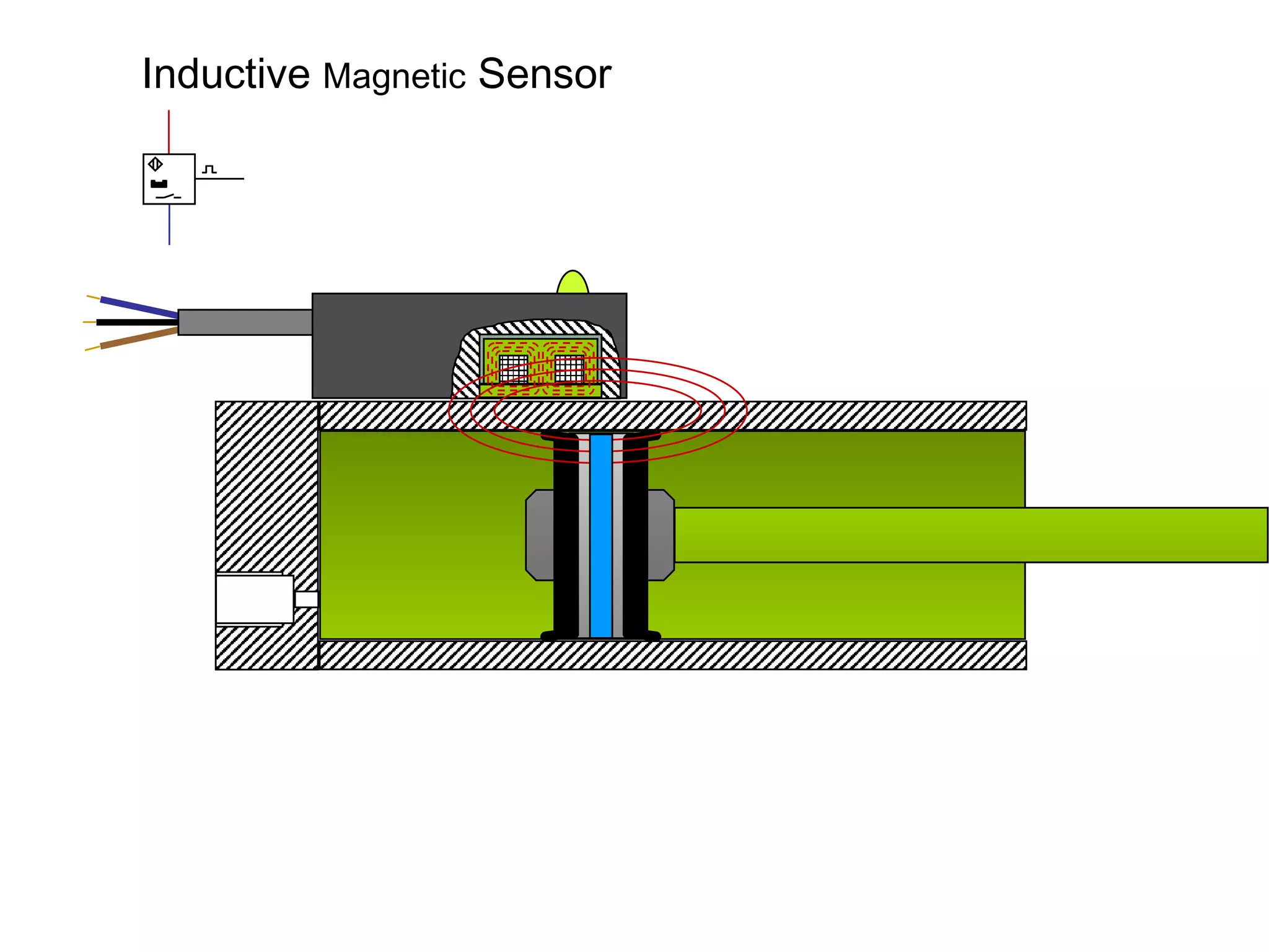
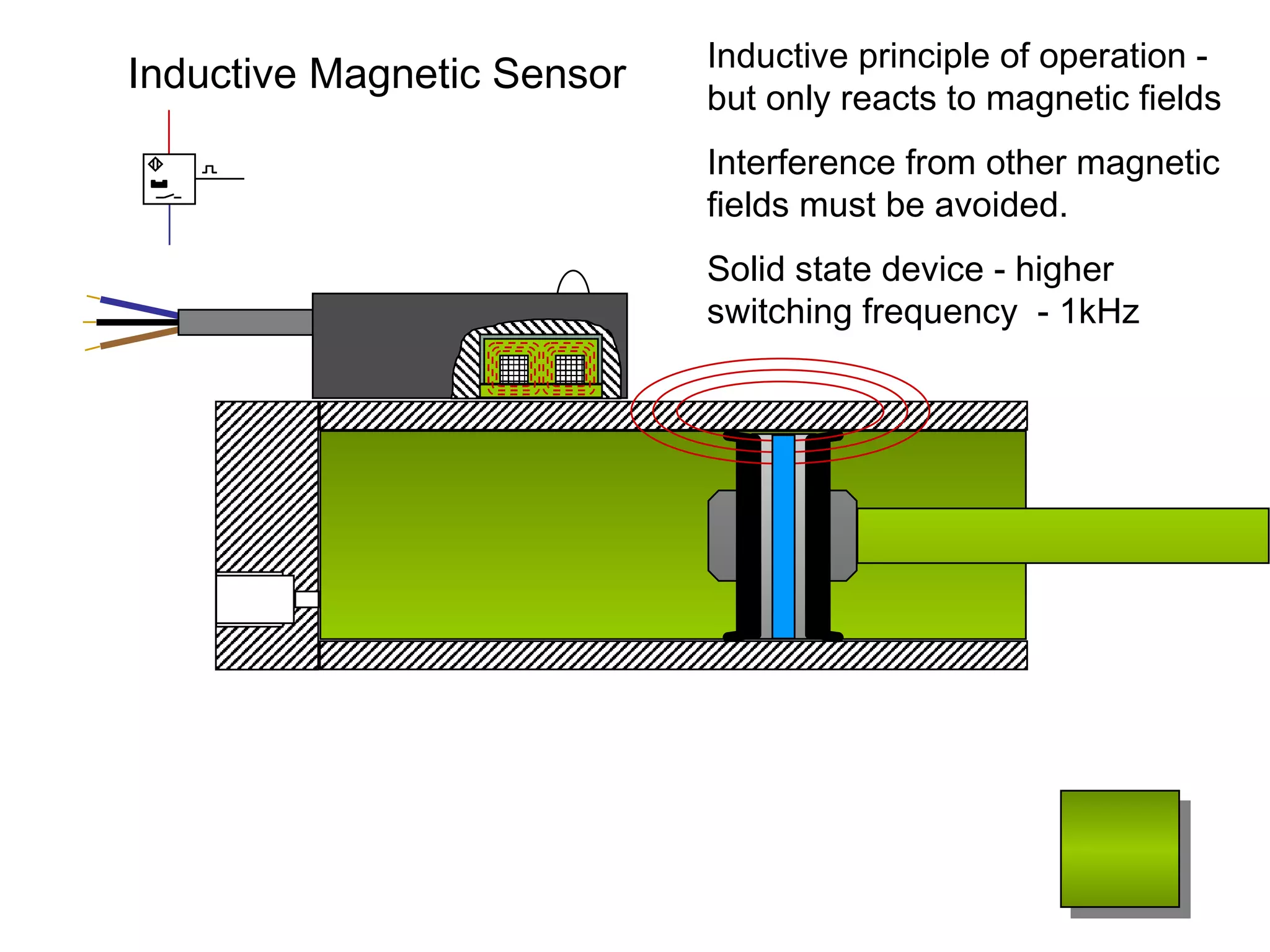
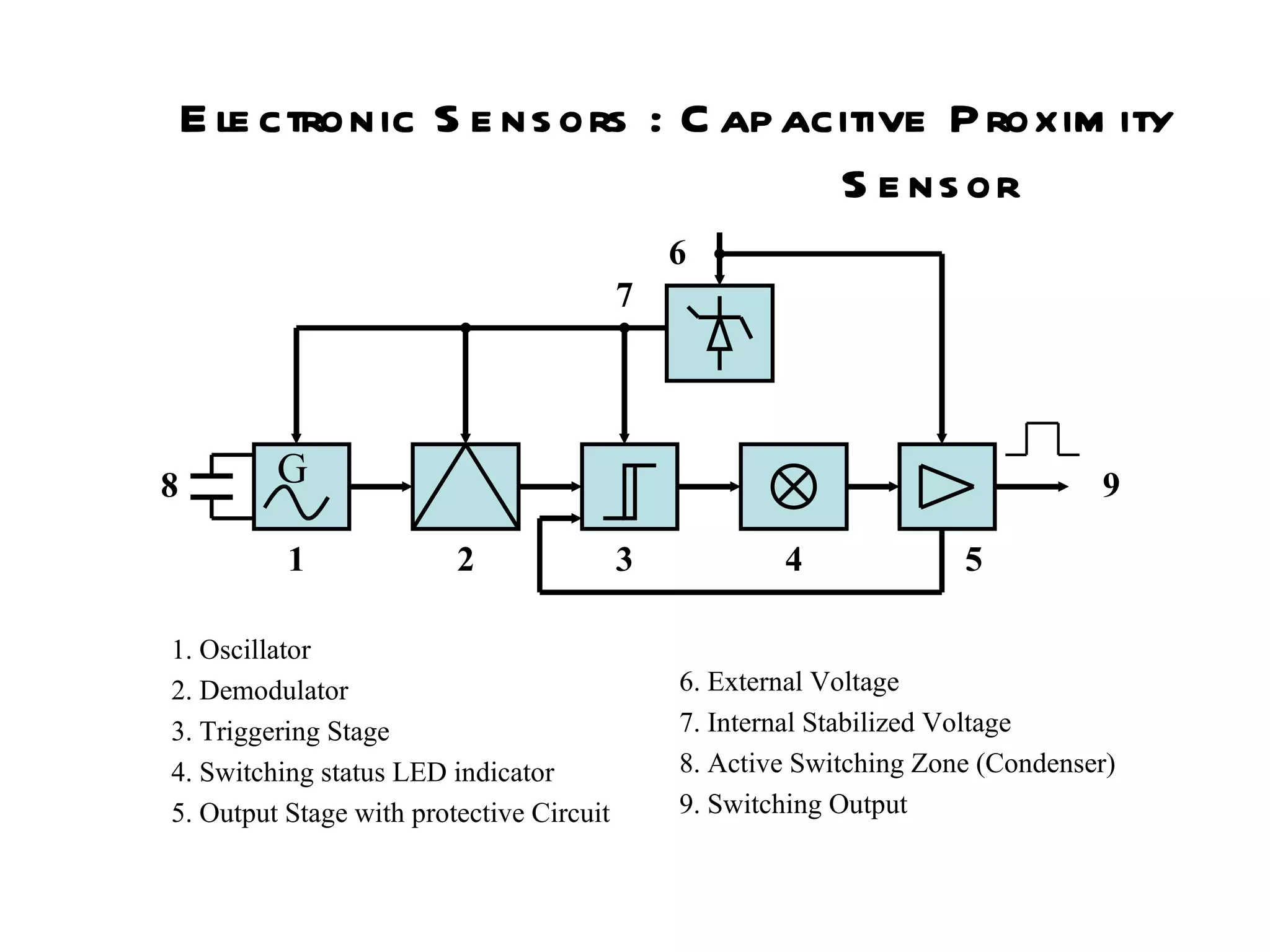
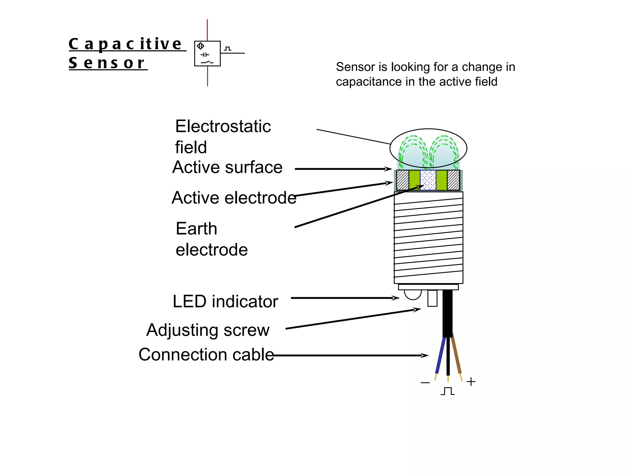
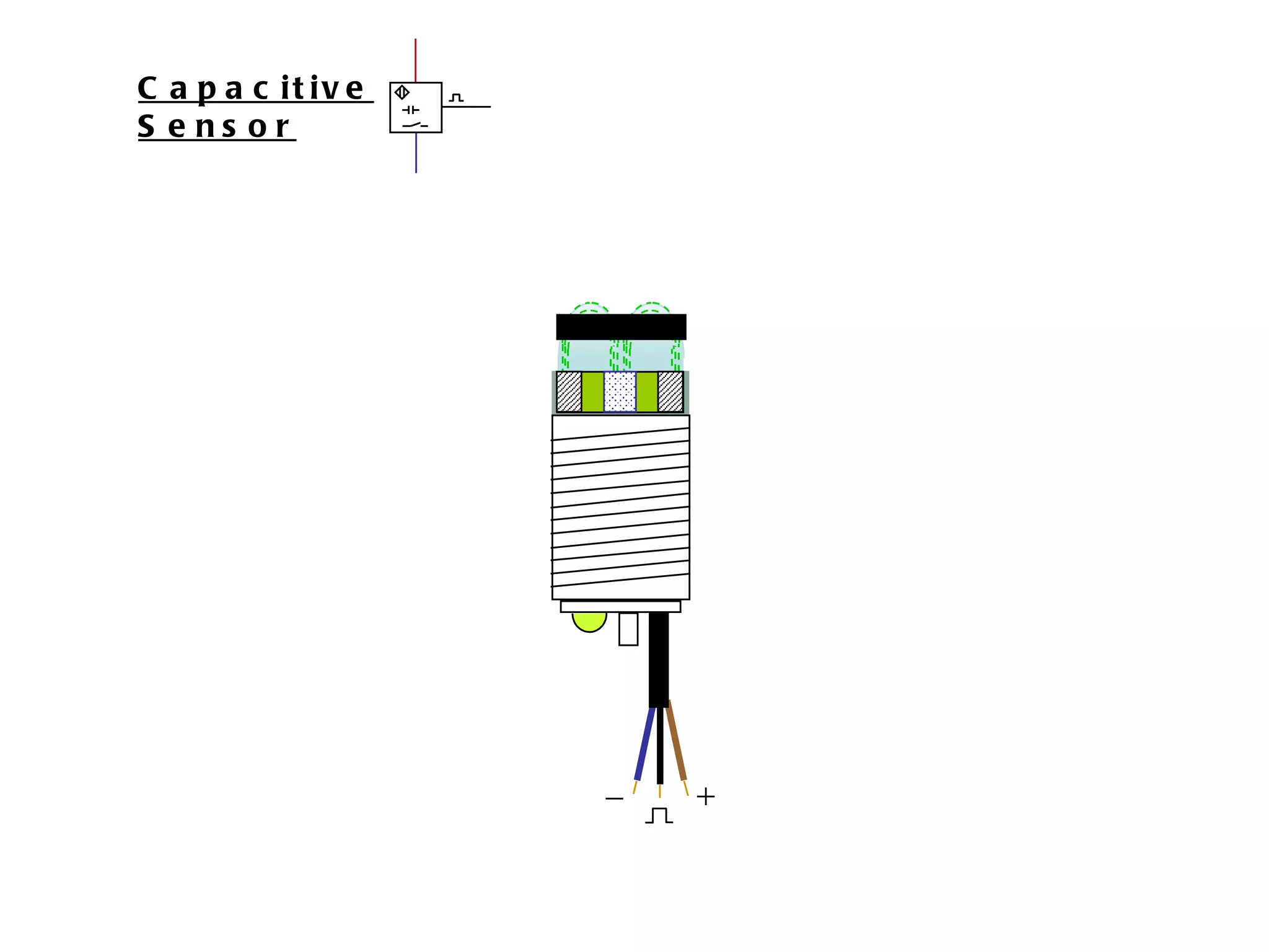
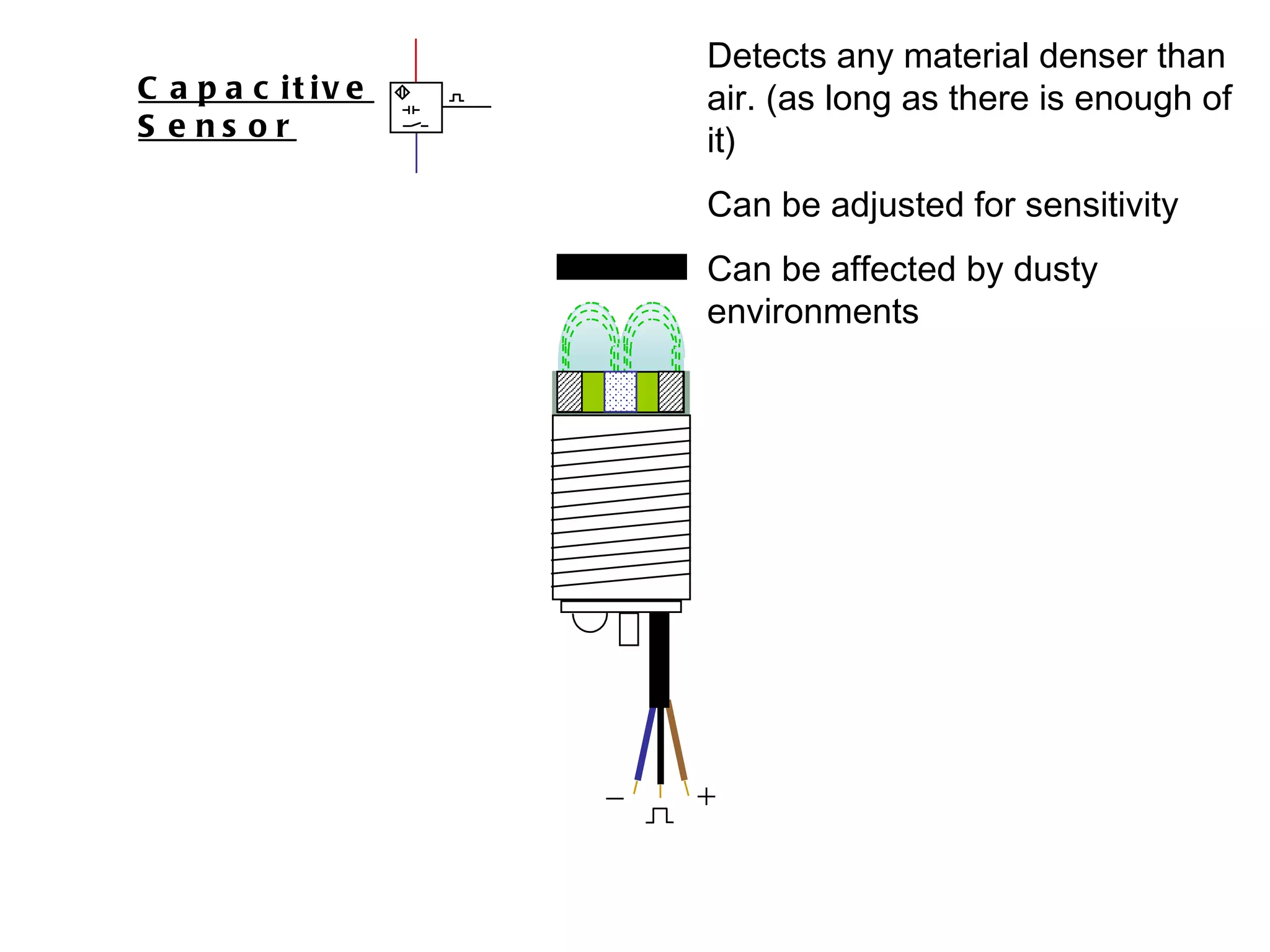
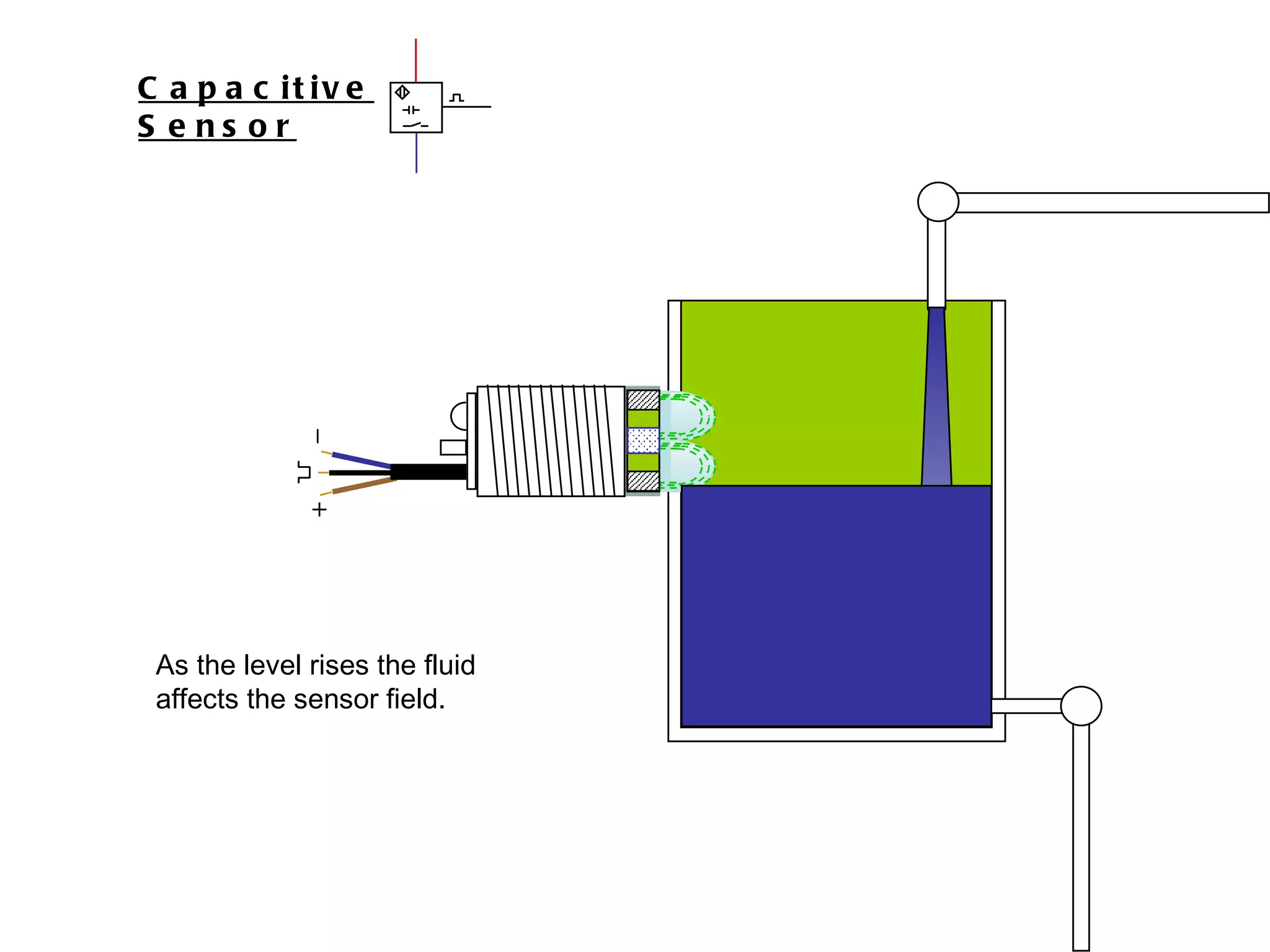
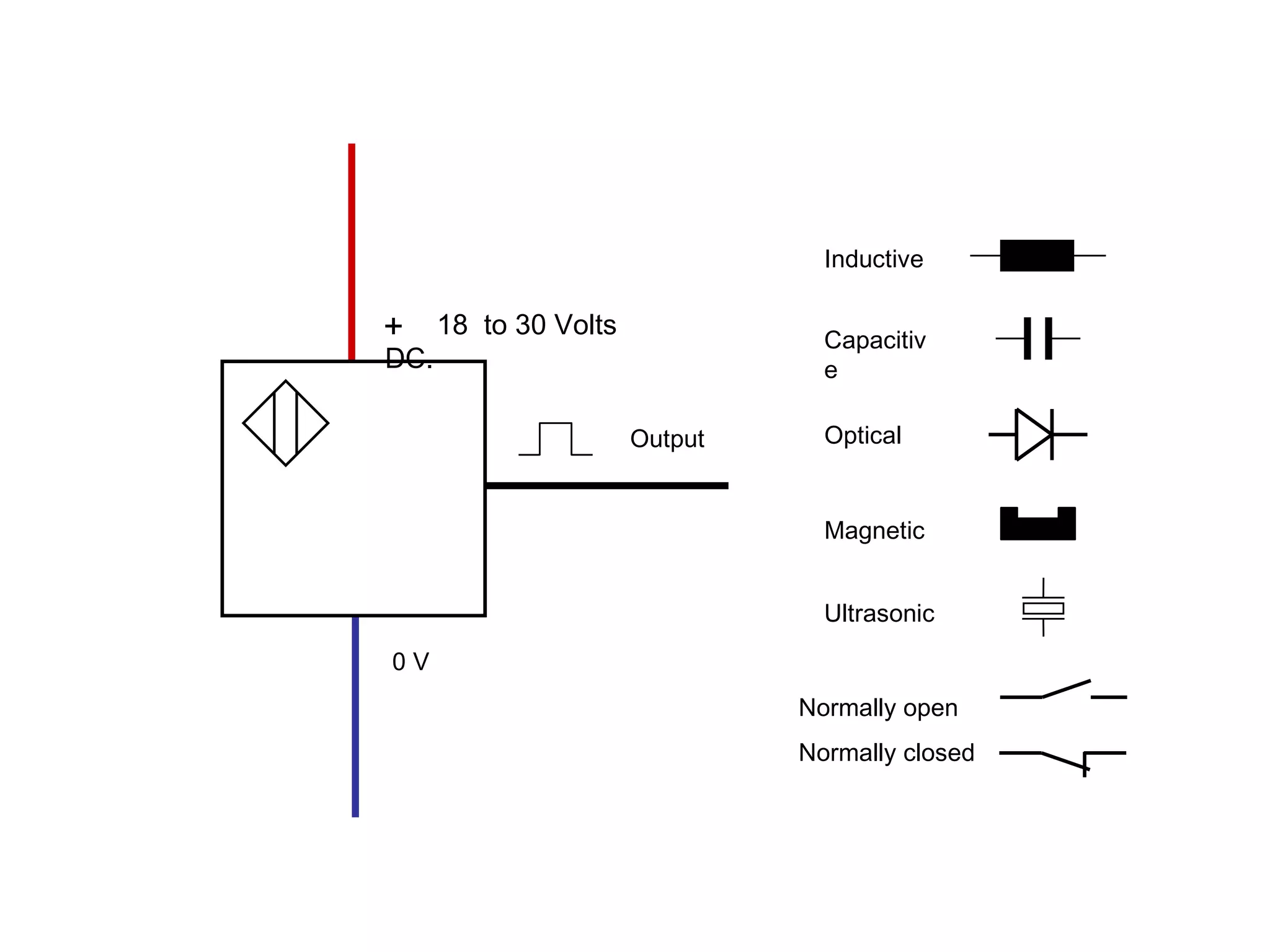
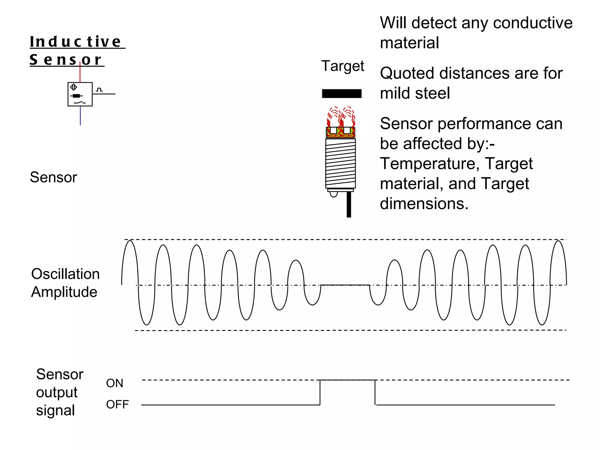
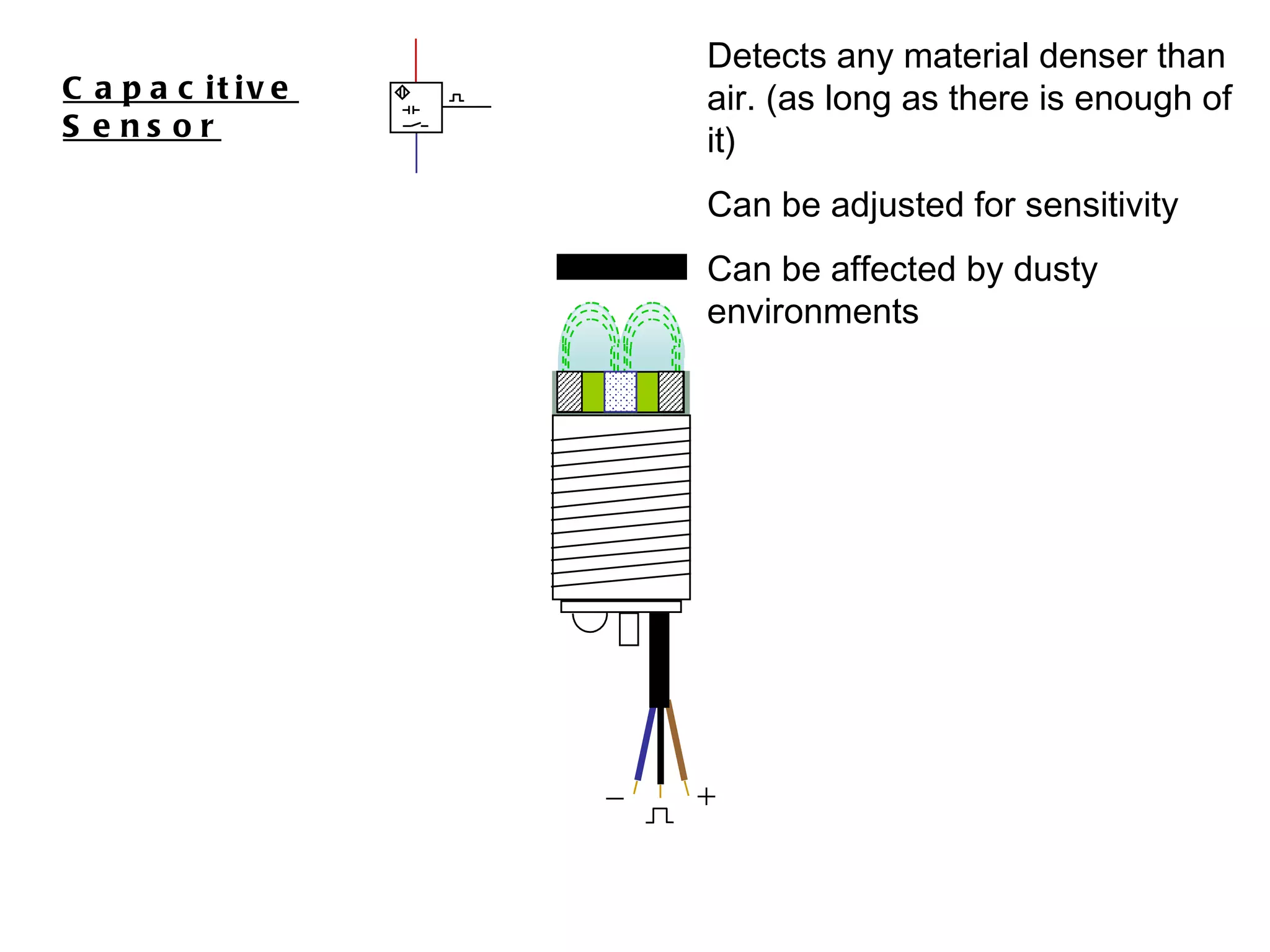
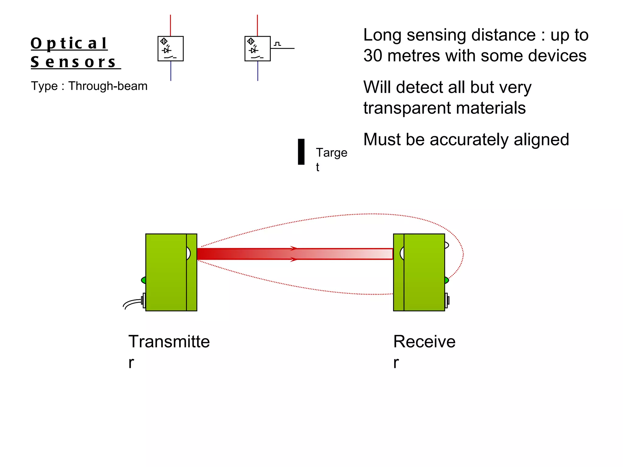
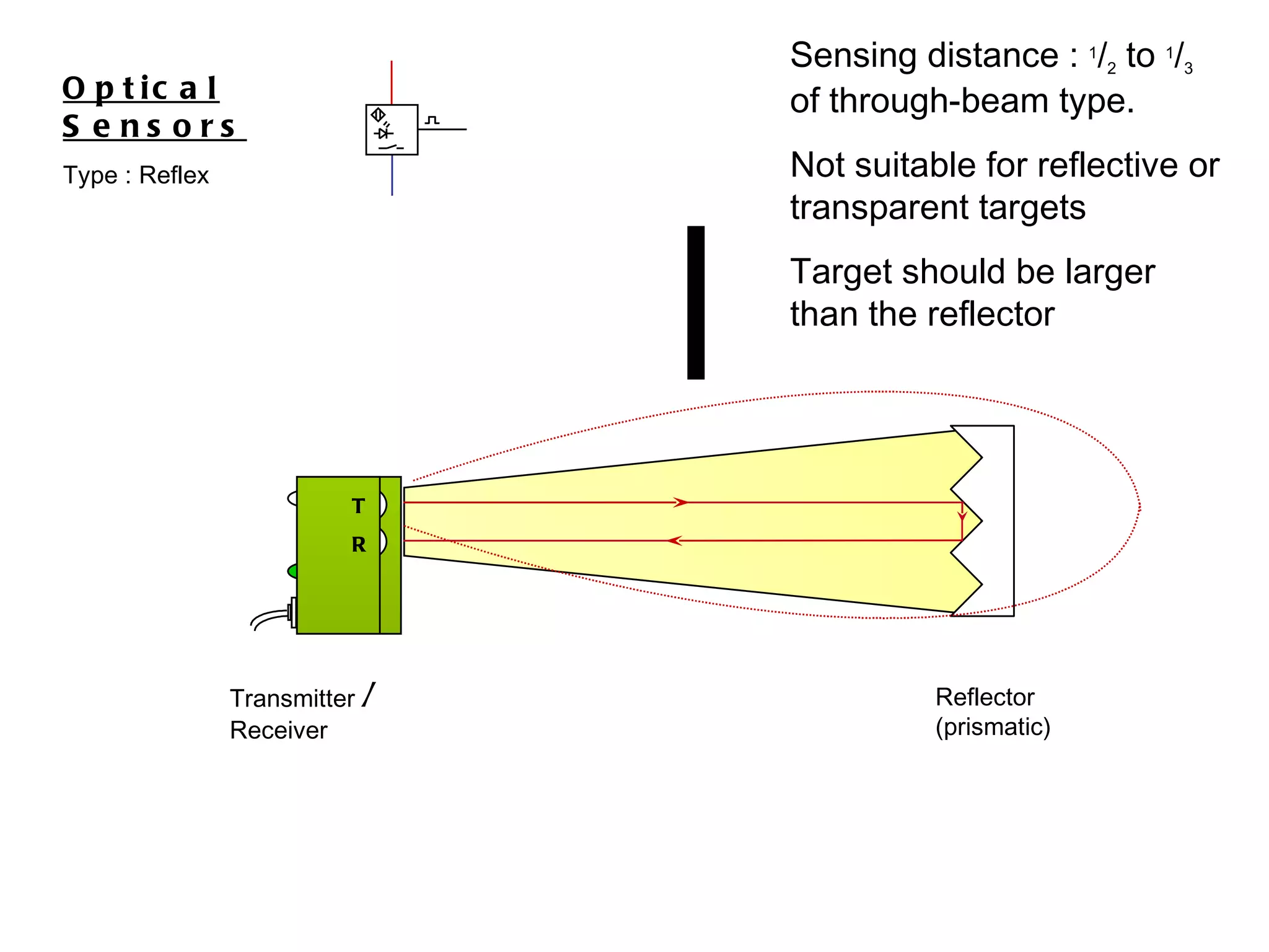
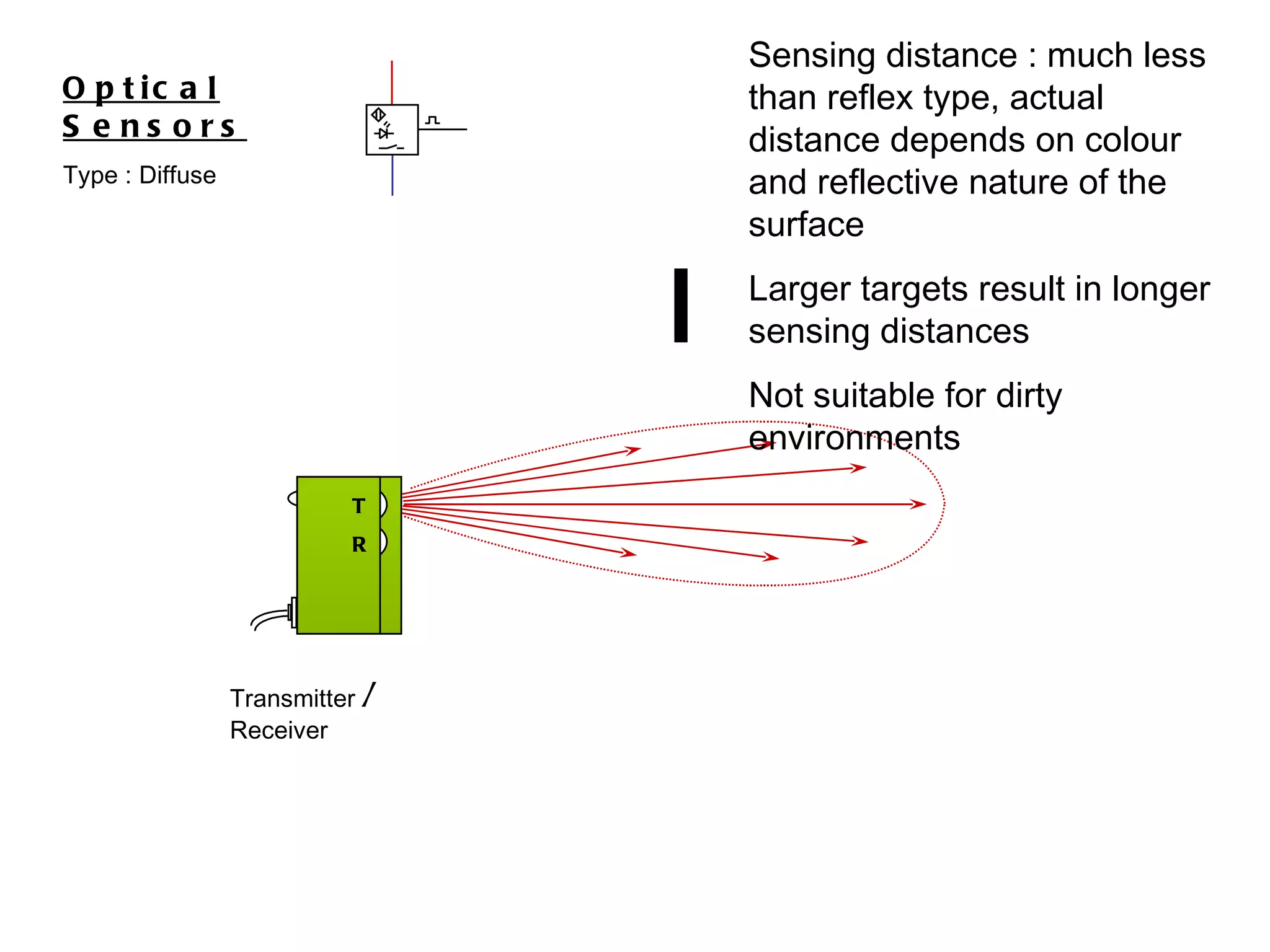
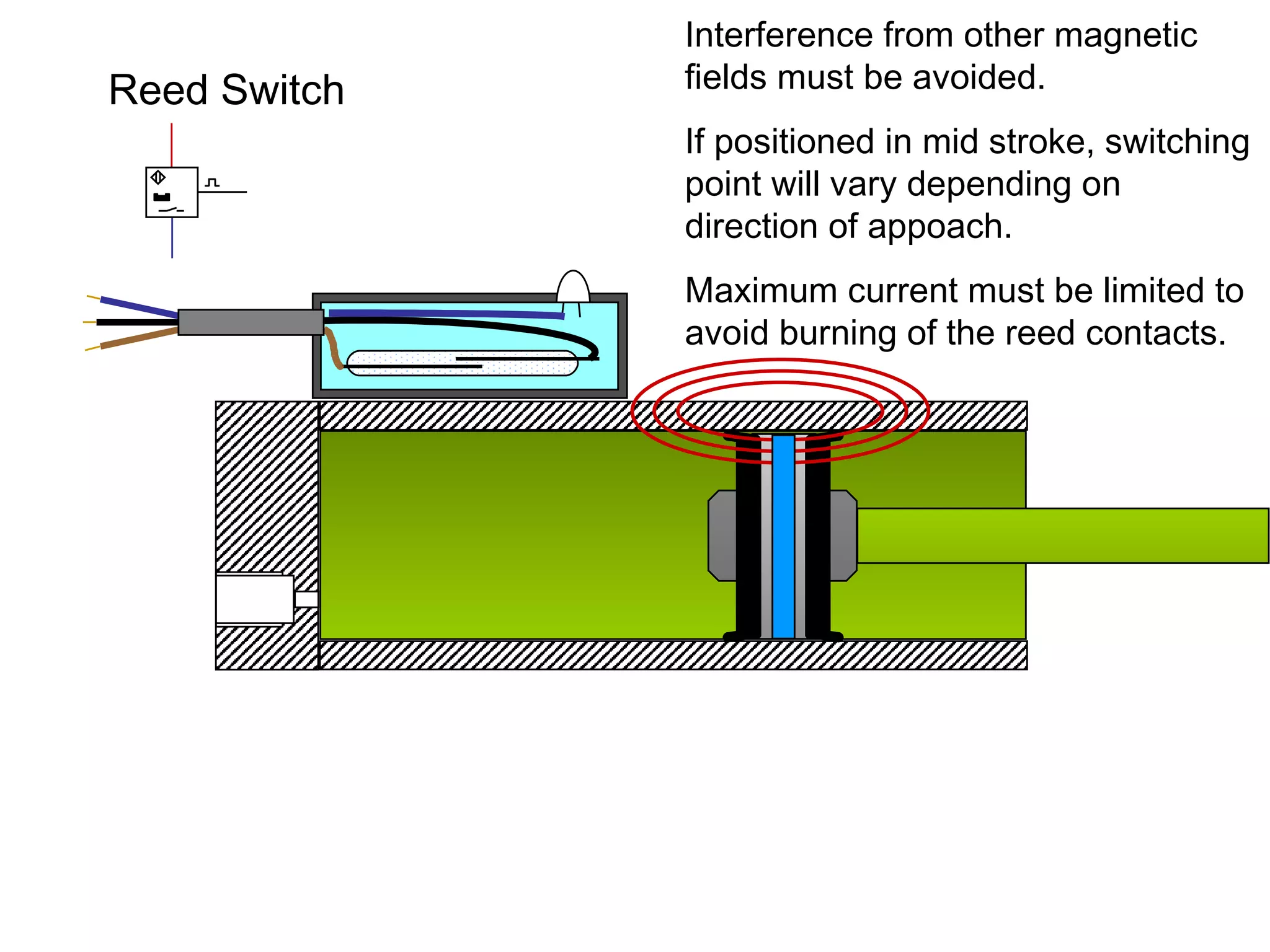
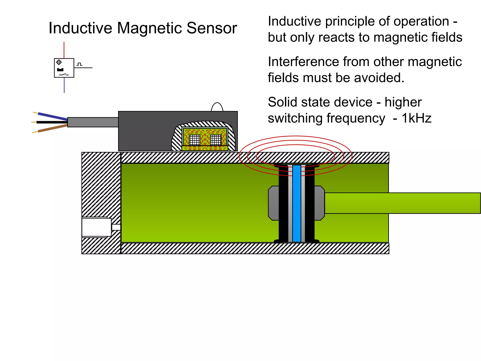
SENSORS
2 Classification of Sensor based on Output Discrete  (sometimes called  digital ,  logic , or  bang-bang )  - sensors provide a single logical output (a zero or one) Proportional  (sometimes called  analog ) - provide an analog output. The output may be a voltage, current, resistance, or even a digital word containing a discrete value.
For discrete sensors, there are two types of outputs the  NPN  or  sinking  output,  the  PNP  or  sourcing  output
+  18  to 30 Volts DC. 0 V Output 24v  DC 0v PNP  Type   Output  is Positive Positive switching
+  18  to 30 Volts DC. 0 V Output 24v  DC 0v NPN  Type   Output  switches through to 0v Negative switching
Proximity Sensors Optical Inductive Reed Switch Inductive Magnetic Capacitive Symbols Connection
Optical Sensors Type : Through-beam
Electronic Sensors : Capacitive Proximity Sensor G 1. Oscillator 2. Demodulator 3. Triggering Stage 4. Switching status LED indicator 5. Output Stage with protective Circuit 6. External Voltage 7. Internal Stabilized Voltage 8. Active Switching Zone (Condenser) 9. Switching Output 1 2 3 4 5 9 7 6 8
Target Optical Sensors Type : Through-beam Transmitter Receiver
Optical Sensors Type : Through-beam Transmitter Receiver
Optical Sensors Type : Retro reflective
Optical Sensors Type : Retro reflective Reflector (prismatic) Transmitter  /  Receiver T R
Transmitter  /  Receiver Reflector (prismatic) T R Optical Sensors Type : Retro reflective
Optical Sensors Type : Diffuse
Optical Sensors Type : Diffuse Target Transmitter  /  Receiver T R
Transmitter  /  Receiver Optical Sensors Type : Diffuse T R
Transmitter  /  Receiver Optical Sensors Type : Diffuse Sensing distance : much less than reflex type, actual distance depends on colour and reflective nature of the surface Larger targets result in longer sensing distances  Not suitable for dirty environments T R
Inductive Sensor
Electronic Sensors : Inductive Proximity   Sensor G 1. Oscillator 2. Demodulator 3. Triggering Stage 4. Switching status LED indicator 5. Output Stage with protective Circuit 6. External Voltage 7. Internal Stabilized Voltage 8. Active Switching Zone (Coil) 9. Switching Output 1 2 3 4 5 9 7 6 8
Connection cable LED indicator Resonant circuit coil Active surface High Frequency magnetic field (300 to 800 kHz)  Inductive Sensor
Sensor Oscillation Amplitude Sensor output signal ON OFF Target Inductive Sensor
Oscillation Amplitude Sensor output signal ON OFF Sensor Target Inductive Sensor
Oscillation Amplitude Sensor output signal ON OFF Sensor Will detect any conductive material Quoted distances are for mild steel Sensor performance can be affected by:-  Temperature, Target material, and Target dimensions. Target Inductive Sensor
Reed Switch
Glass Tube filled with nitrogen Reed contacts LED indicator
Reed Switch 24v
Interference from other magnetic fields must be avoided. If positioned in mid stroke, switching point will vary depending on direction of appoach. Maximum current must be limited to avoid burning of the reed contacts. Reed Switch
Inductive Magnetic Sensor
Connection cable LED Indicator Resonant circuit coil High Frequency magnetic field Inductive Magnetic Sensor
Inductive  Magnetic  Sensor
Inductive principle of operation - but only reacts to magnetic fields Interference from other magnetic fields must be avoided. Solid state device - higher switching frequency  - 1kHz Inductive Magnetic Sensor
Capacitive Sensor
Electronic Sensors : Capacitive Proximity   Sensor G 1. Oscillator 2. Demodulator 3. Triggering Stage 4. Switching status LED indicator 5. Output Stage with protective Circuit 6. External Voltage 7. Internal Stabilized Voltage 8. Active Switching Zone (Condenser) 9. Switching Output 1 2 3 4 5 9 7 6 8
Connection cable Adjusting screw LED indicator Active surface Active electrode Earth electrode Electrostatic field Sensor is looking for a change in capacitance in the active field Capacitive Sensor
Capacitive Sensor
Capacitive Sensor Detects any material denser than air. (as long as there is enough of it)  Can be adjusted for sensitivity Can be affected by dusty environments
Capacitive Sensor As the level rises the fluid affects the sensor field.
Sensor Symbols
+  18  to 30 Volts DC. 0 V Output Inductive Capacitive Optical Magnetic Ultrasonic Normally open Normally closed
 
Oscillation Amplitude Sensor output signal ON OFF Sensor Will detect any conductive material Quoted distances are for mild steel Sensor performance can be affected by:-  Temperature, Target material, and Target dimensions. Target Inductive Sensor
Capacitive Sensor Detects any material denser than air. (as long as there is enough of it)  Can be adjusted for sensitivity Can be affected by dusty environments
Target Optical Sensors Type : Through-beam Long sensing distance : up to 30 metres with some devices Will detect all but very transparent materials Must be accurately aligned Transmitter Receiver
Transmitter  /  Receiver Optical Sensors Type : Reflex Reflector (prismatic) Sensing distance :  1 / 2  to  1 / 3  of through-beam type. Not suitable for reflective or transparent targets Target should be larger than the reflector T R
Transmitter  /  Receiver Optical Sensors Type : Diffuse Sensing distance : much less than reflex type, actual distance depends on colour and reflective nature of the surface Larger targets result in longer sensing distances  Not suitable for dirty environments T R
Interference from other magnetic fields must be avoided. If positioned in mid stroke, switching point will vary depending on direction of appoach. Maximum current must be limited to avoid burning of the reed contacts. Reed Switch
Inductive principle of operation - but only reacts to magnetic fields Interference from other magnetic fields must be avoided. Solid state device - higher switching frequency  - 1kHz Inductive Magnetic Sensor

Sensors

  • 1.
  • 2.
    2 Classification ofSensor based on Output Discrete (sometimes called digital , logic , or bang-bang ) - sensors provide a single logical output (a zero or one) Proportional (sometimes called analog ) - provide an analog output. The output may be a voltage, current, resistance, or even a digital word containing a discrete value.
  • 3.
    For discrete sensors,there are two types of outputs the NPN or sinking output, the PNP or sourcing output
  • 4.
    + 18 to 30 Volts DC. 0 V Output 24v DC 0v PNP Type Output is Positive Positive switching
  • 5.
    + 18 to 30 Volts DC. 0 V Output 24v DC 0v NPN Type Output switches through to 0v Negative switching
  • 6.
    Proximity Sensors OpticalInductive Reed Switch Inductive Magnetic Capacitive Symbols Connection
  • 7.
    Optical Sensors Type: Through-beam
  • 8.
    Electronic Sensors :Capacitive Proximity Sensor G 1. Oscillator 2. Demodulator 3. Triggering Stage 4. Switching status LED indicator 5. Output Stage with protective Circuit 6. External Voltage 7. Internal Stabilized Voltage 8. Active Switching Zone (Condenser) 9. Switching Output 1 2 3 4 5 9 7 6 8
  • 9.
    Target Optical SensorsType : Through-beam Transmitter Receiver
  • 10.
    Optical Sensors Type: Through-beam Transmitter Receiver
  • 11.
    Optical Sensors Type: Retro reflective
  • 12.
    Optical Sensors Type: Retro reflective Reflector (prismatic) Transmitter / Receiver T R
  • 13.
    Transmitter / Receiver Reflector (prismatic) T R Optical Sensors Type : Retro reflective
  • 14.
    Transmitter / Receiver Reflector (prismatic) T R Optical Sensors Type : Retro reflective
  • 15.
  • 16.
    Optical Sensors Type: Diffuse Target Transmitter / Receiver T R
  • 17.
    Transmitter / Receiver Optical Sensors Type : Diffuse T R
  • 18.
    Transmitter / Receiver Optical Sensors Type : Diffuse Sensing distance : much less than reflex type, actual distance depends on colour and reflective nature of the surface Larger targets result in longer sensing distances Not suitable for dirty environments T R
  • 19.
  • 20.
    Electronic Sensors :Inductive Proximity Sensor G 1. Oscillator 2. Demodulator 3. Triggering Stage 4. Switching status LED indicator 5. Output Stage with protective Circuit 6. External Voltage 7. Internal Stabilized Voltage 8. Active Switching Zone (Coil) 9. Switching Output 1 2 3 4 5 9 7 6 8
  • 21.
    Connection cable LEDindicator Resonant circuit coil Active surface High Frequency magnetic field (300 to 800 kHz) Inductive Sensor
  • 22.
    Sensor Oscillation AmplitudeSensor output signal ON OFF Target Inductive Sensor
  • 23.
    Oscillation Amplitude Sensoroutput signal ON OFF Sensor Target Inductive Sensor
  • 24.
    Oscillation Amplitude Sensoroutput signal ON OFF Sensor Will detect any conductive material Quoted distances are for mild steel Sensor performance can be affected by:- Temperature, Target material, and Target dimensions. Target Inductive Sensor
  • 25.
  • 26.
    Glass Tube filledwith nitrogen Reed contacts LED indicator
  • 27.
  • 28.
    Interference from othermagnetic fields must be avoided. If positioned in mid stroke, switching point will vary depending on direction of appoach. Maximum current must be limited to avoid burning of the reed contacts. Reed Switch
  • 29.
  • 30.
    Connection cable LEDIndicator Resonant circuit coil High Frequency magnetic field Inductive Magnetic Sensor
  • 31.
  • 32.
    Inductive principle ofoperation - but only reacts to magnetic fields Interference from other magnetic fields must be avoided. Solid state device - higher switching frequency - 1kHz Inductive Magnetic Sensor
  • 33.
  • 34.
    Electronic Sensors :Capacitive Proximity Sensor G 1. Oscillator 2. Demodulator 3. Triggering Stage 4. Switching status LED indicator 5. Output Stage with protective Circuit 6. External Voltage 7. Internal Stabilized Voltage 8. Active Switching Zone (Condenser) 9. Switching Output 1 2 3 4 5 9 7 6 8
  • 35.
    Connection cable Adjustingscrew LED indicator Active surface Active electrode Earth electrode Electrostatic field Sensor is looking for a change in capacitance in the active field Capacitive Sensor
  • 36.
  • 37.
    Capacitive Sensor Detectsany material denser than air. (as long as there is enough of it) Can be adjusted for sensitivity Can be affected by dusty environments
  • 38.
    Capacitive Sensor Asthe level rises the fluid affects the sensor field.
  • 39.
  • 40.
    + 18 to 30 Volts DC. 0 V Output Inductive Capacitive Optical Magnetic Ultrasonic Normally open Normally closed
  • 41.
  • 42.
    Oscillation Amplitude Sensoroutput signal ON OFF Sensor Will detect any conductive material Quoted distances are for mild steel Sensor performance can be affected by:- Temperature, Target material, and Target dimensions. Target Inductive Sensor
  • 43.
    Capacitive Sensor Detectsany material denser than air. (as long as there is enough of it) Can be adjusted for sensitivity Can be affected by dusty environments
  • 44.
    Target Optical SensorsType : Through-beam Long sensing distance : up to 30 metres with some devices Will detect all but very transparent materials Must be accurately aligned Transmitter Receiver
  • 45.
    Transmitter / Receiver Optical Sensors Type : Reflex Reflector (prismatic) Sensing distance : 1 / 2 to 1 / 3 of through-beam type. Not suitable for reflective or transparent targets Target should be larger than the reflector T R
  • 46.
    Transmitter / Receiver Optical Sensors Type : Diffuse Sensing distance : much less than reflex type, actual distance depends on colour and reflective nature of the surface Larger targets result in longer sensing distances Not suitable for dirty environments T R
  • 47.
    Interference from othermagnetic fields must be avoided. If positioned in mid stroke, switching point will vary depending on direction of appoach. Maximum current must be limited to avoid burning of the reed contacts. Reed Switch
  • 48.
    Inductive principle ofoperation - but only reacts to magnetic fields Interference from other magnetic fields must be avoided. Solid state device - higher switching frequency - 1kHz Inductive Magnetic Sensor