Downloaded 246 times


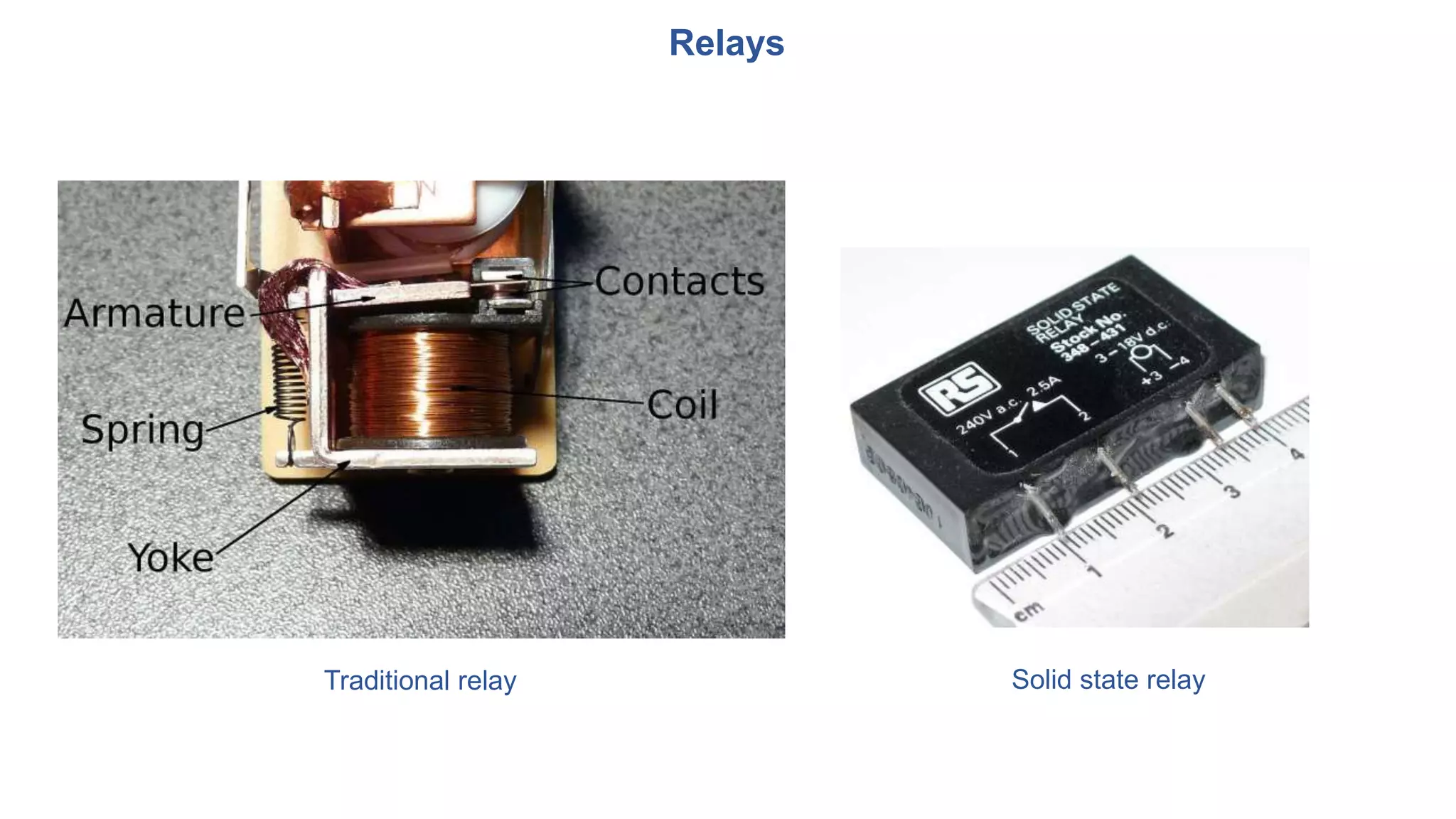


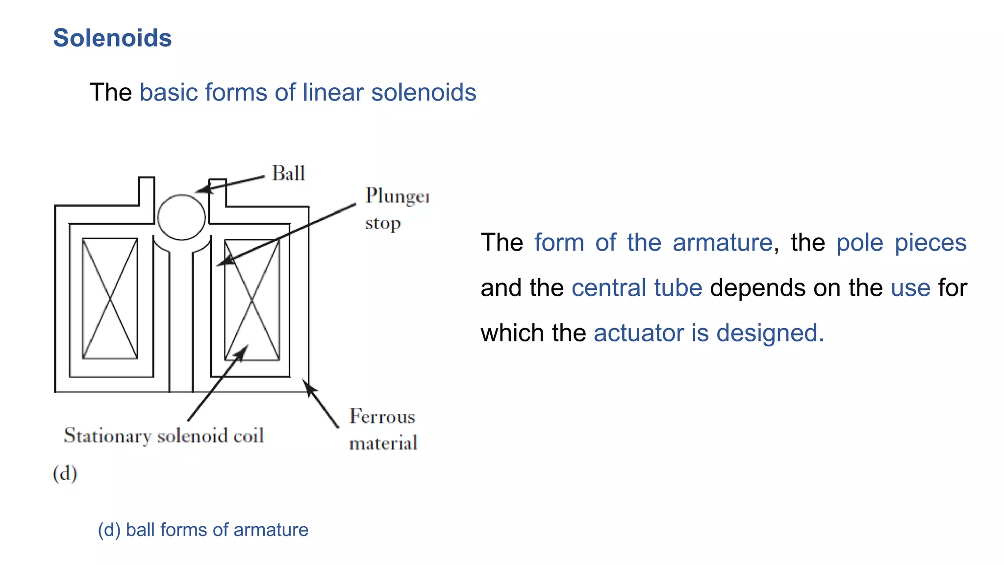

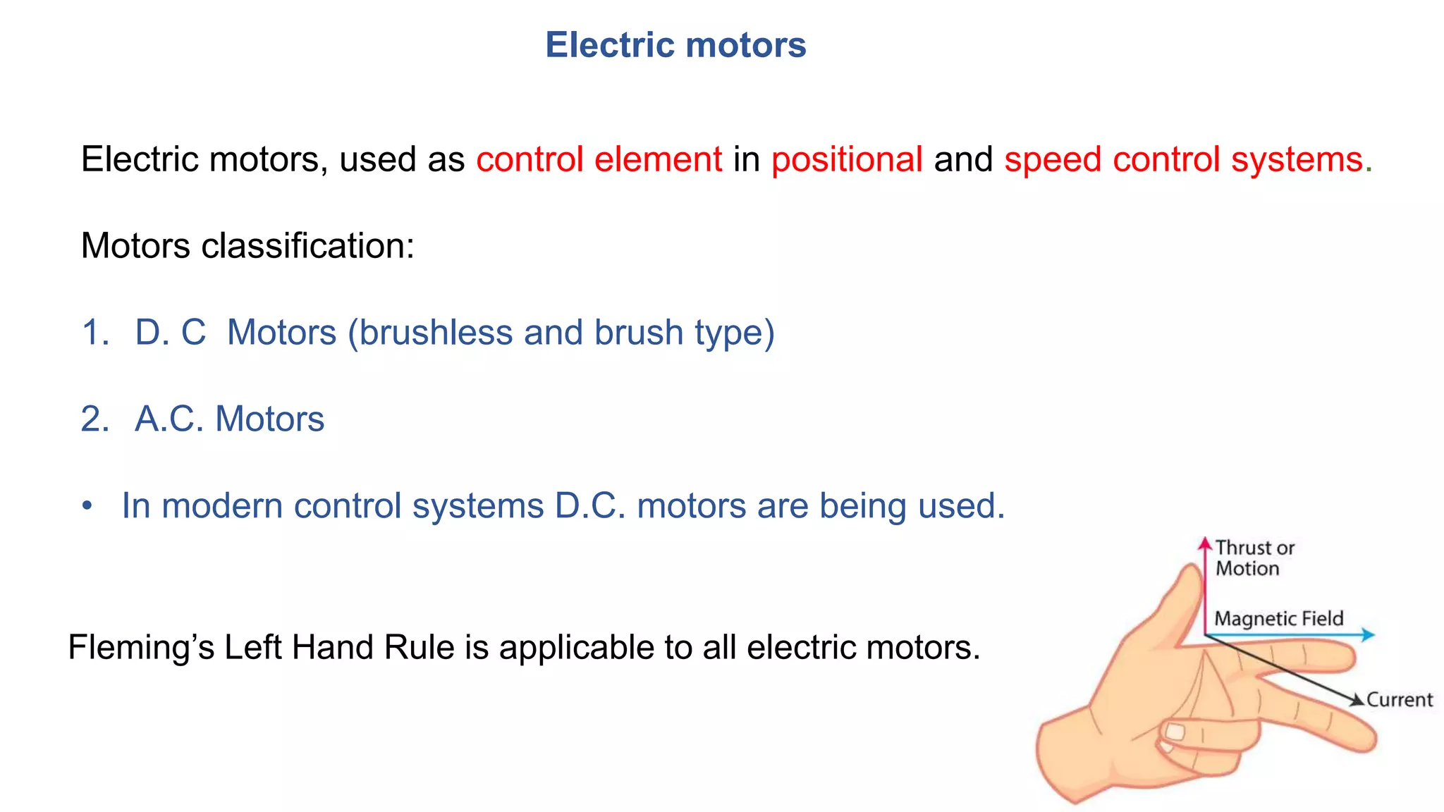


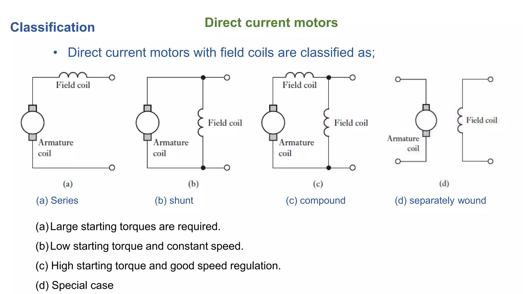
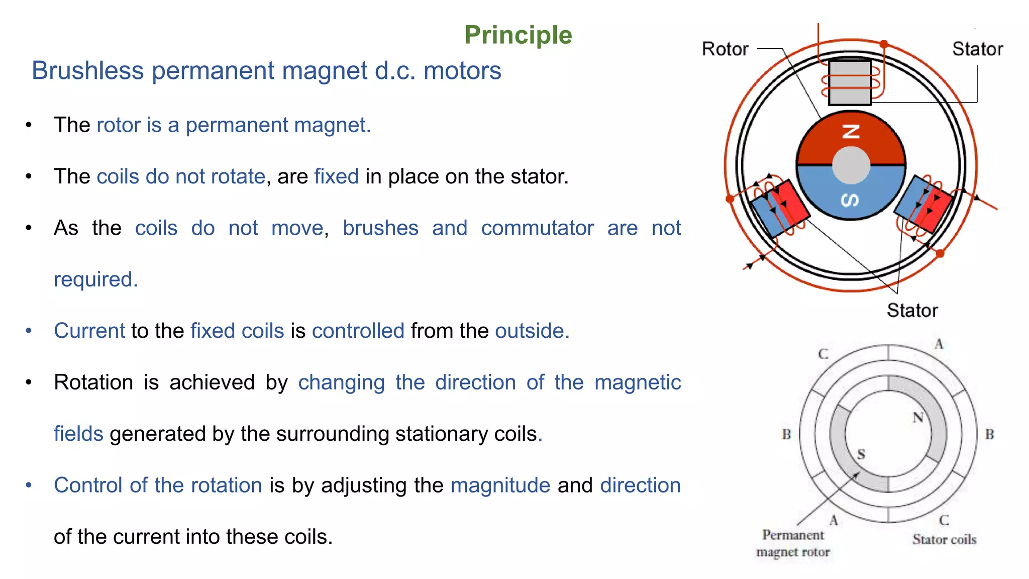

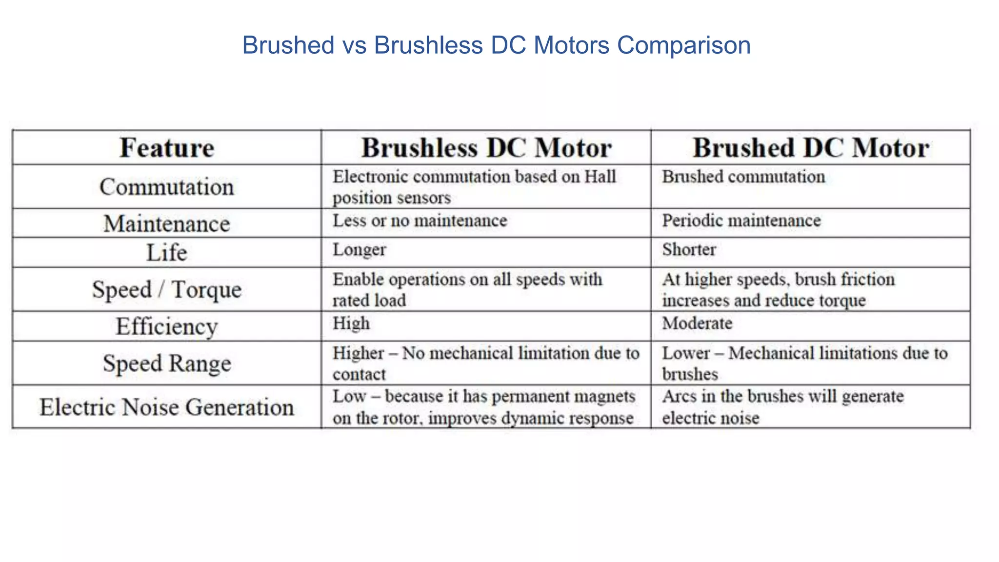
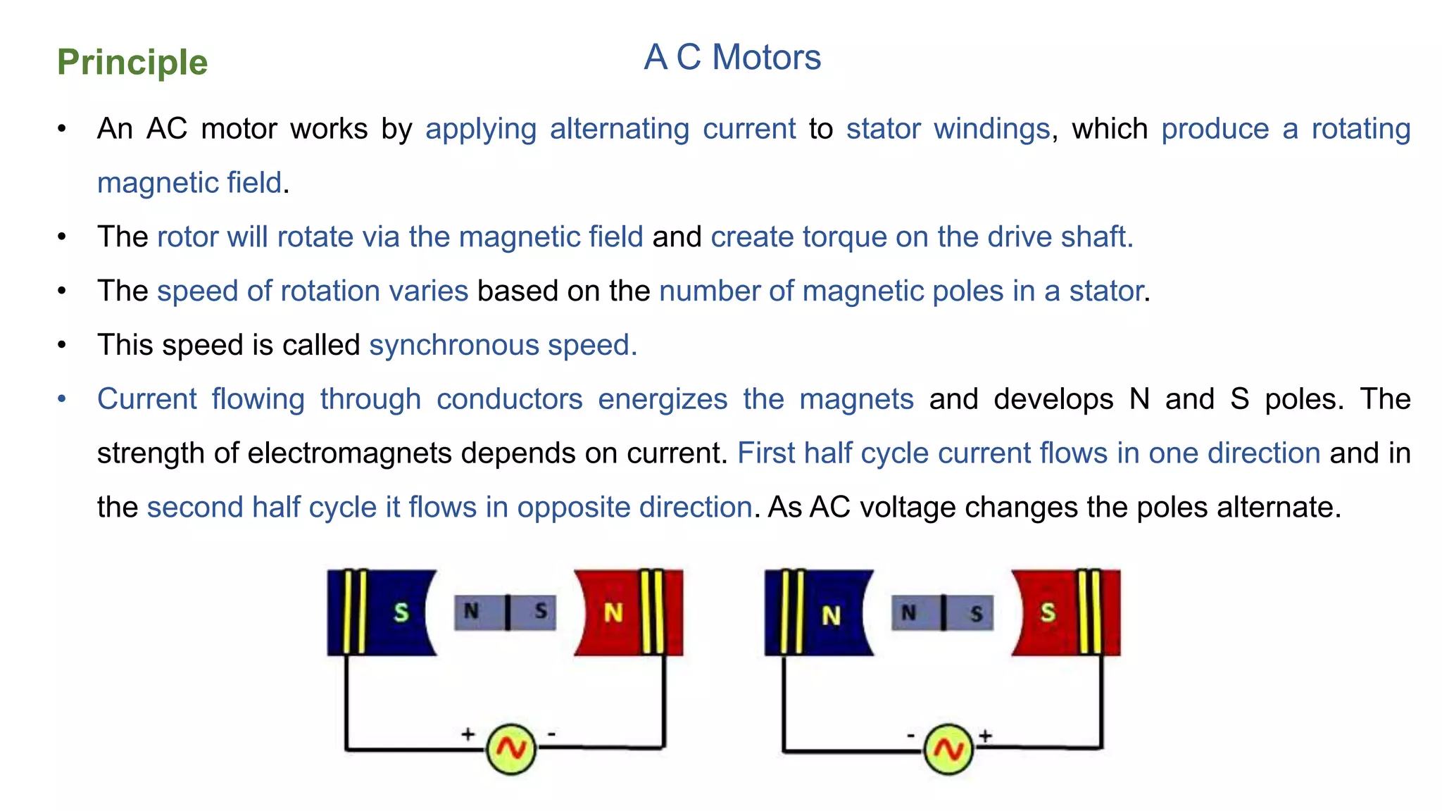


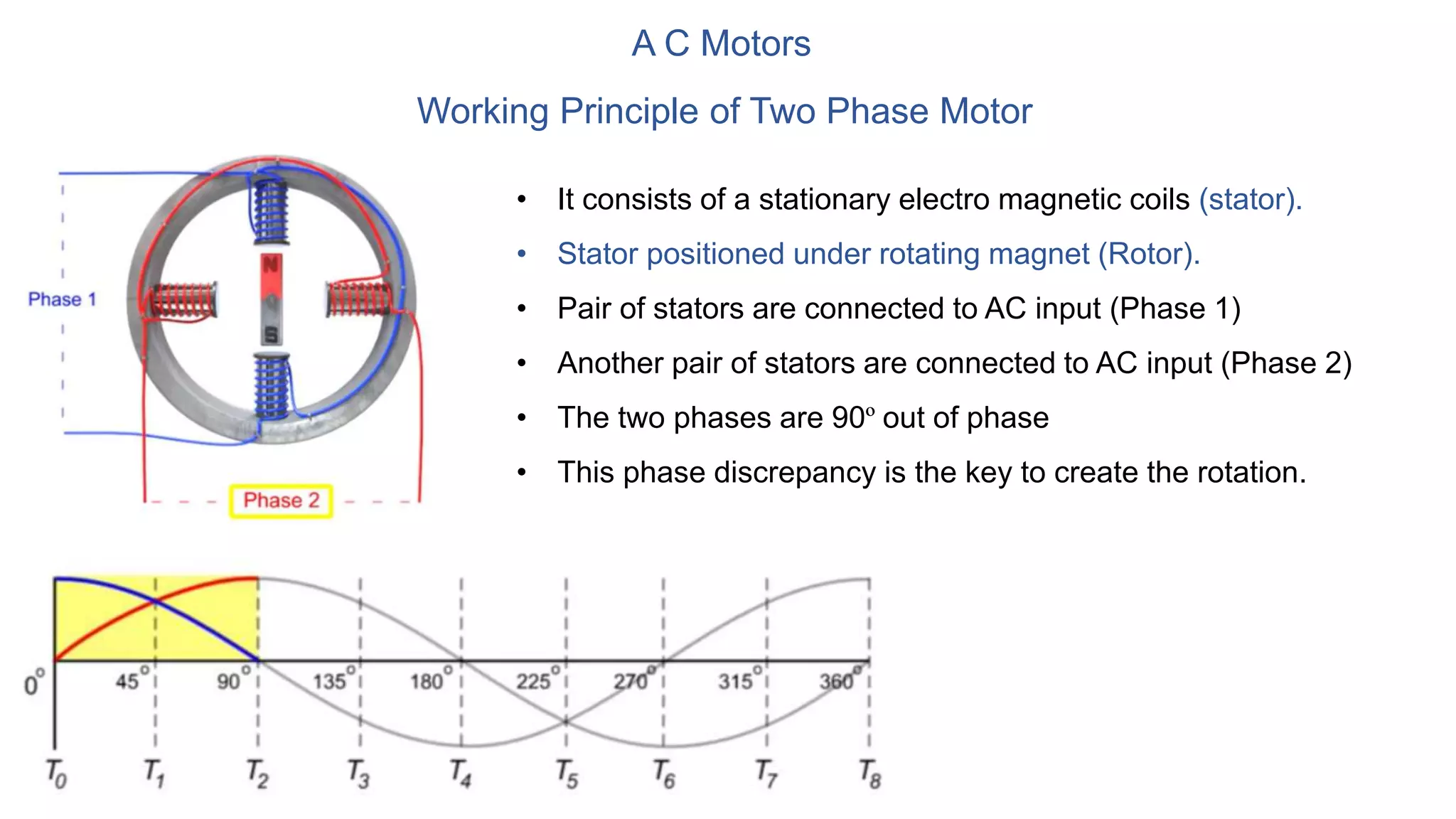
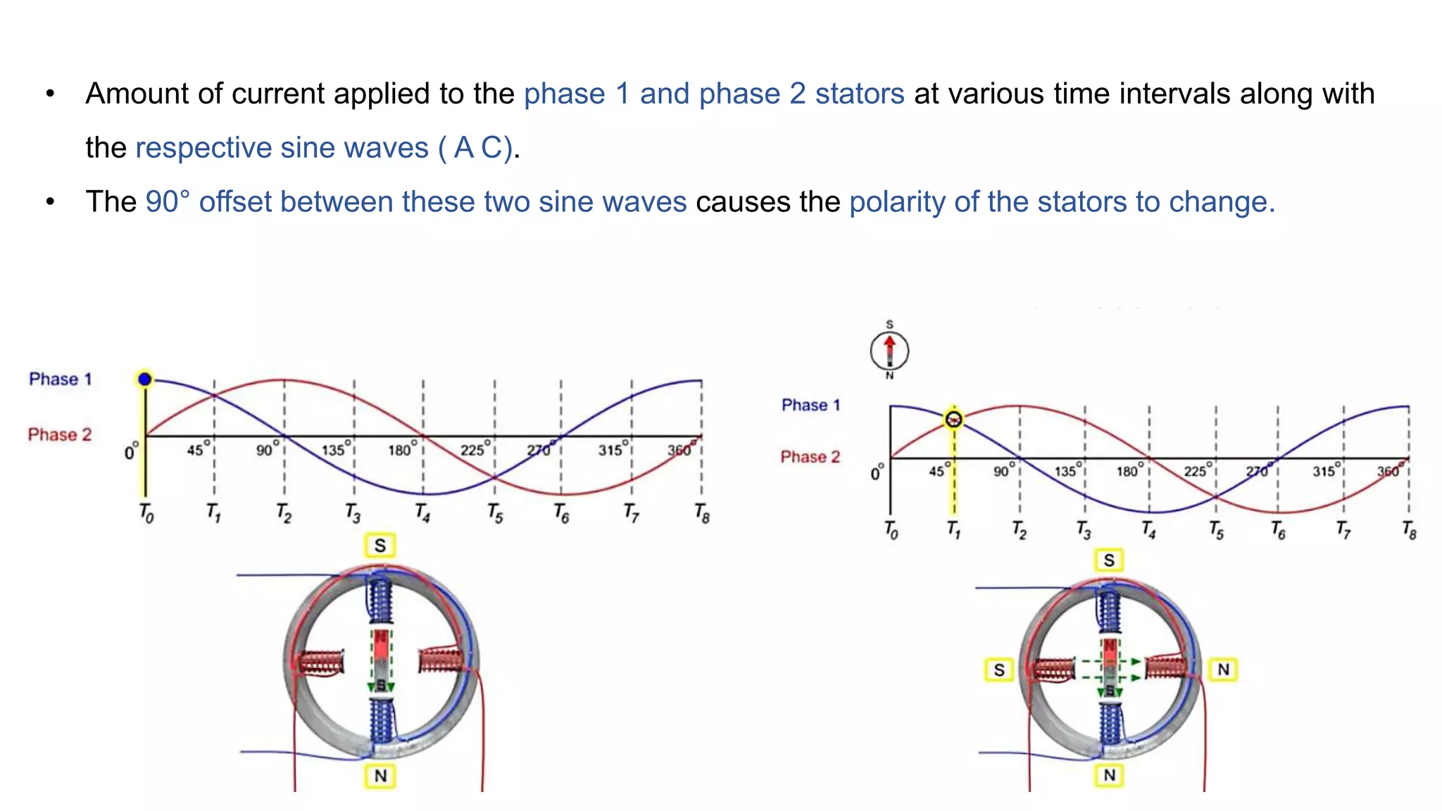

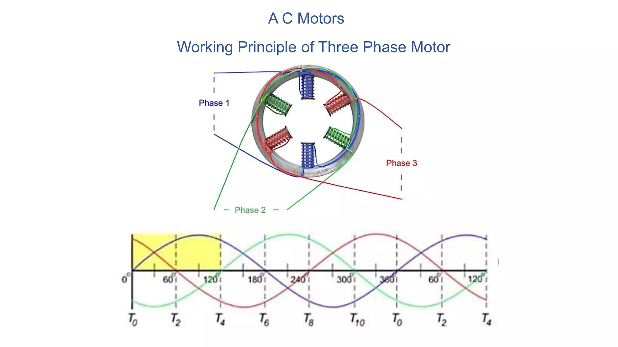


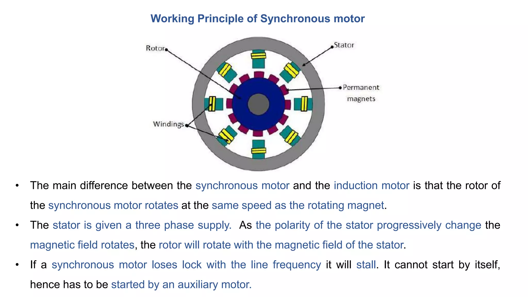
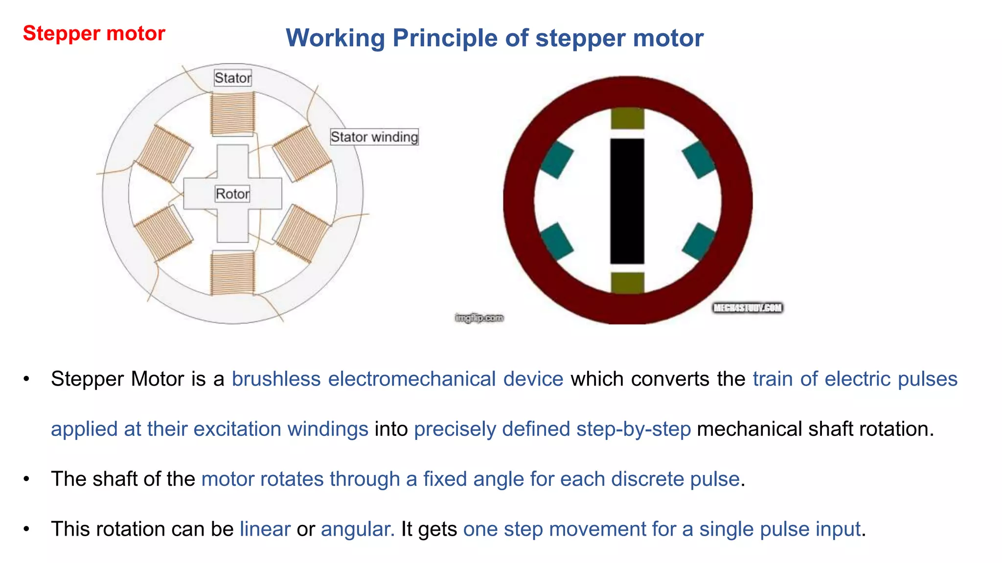


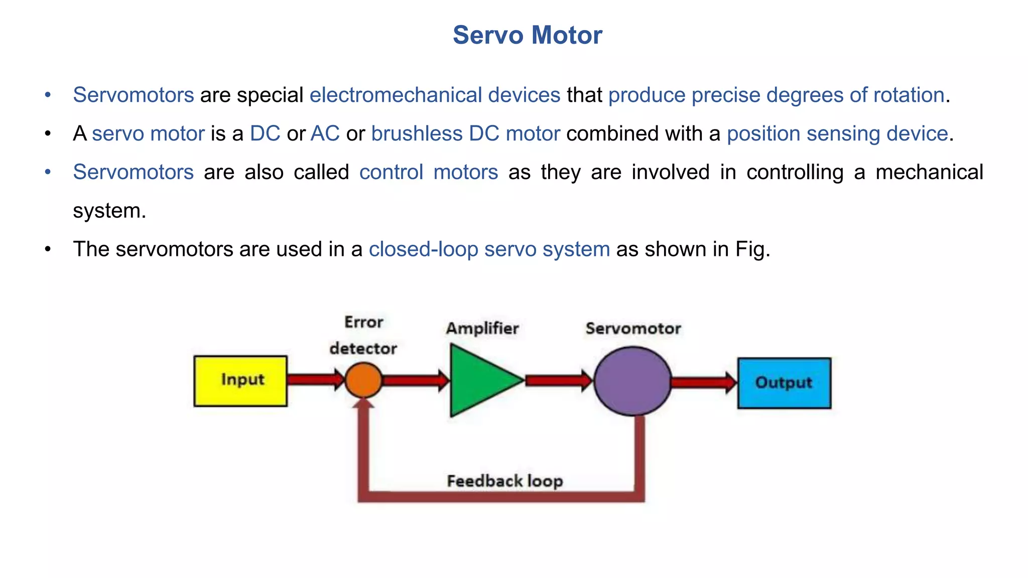


The document provides an overview of various electrical actuation systems used in mechatronics including relays, solenoids, DC motors, AC motors, stepper motors, and servomotors. It describes the basic operational principles, components, types, and applications of each system. Relays use electromagnets to open and close contacts and switch circuits. Solenoids convert electrical signals into linear or rotary motion using coils and armatures. DC and AC motors produce rotation using magnetic fields and current flow according to Fleming's left hand rule. Stepper motors move in discrete steps with each pulse, while servomotors provide precise rotation for control applications.