Downloaded 52 times
![IJSRD - International Journal for Scientific Research & Development| Vol. 2, Issue 07, 2014 | ISSN (online): 2321-0613
All rights reserved by www.ijsrd.com 479
Speed Control of BLDC Motor with Four Quadrant Operation Using
dsPIC
Savitri L. Medegar1
M. S. Aspalli2
1
M.Tech student 2
Assistant Professor
1,2
Department of Electrical & Electronics Engineering
1,2
PDA College of Engineering, Gulbarga, Karnataka, India
Abstract— Brushless DC (BLDC) motor drives are
becoming more popular in industrial and traction
applications. Hence the control of BLDC motor in four
quadrants is very vital. The flexibility of the drive system is
increased using digital controller. In this paper the PWM
signals for driving the power inverter bridge for BLDC
motor have been successfully implemented using a dsPIC
controller and the motor can be controlled in all the four
quadrants without any loss of power .Energy is conserved
during regenerative braking period. The digital controller
dsPIC, is advantageous over other controller, as it combines
the calculation capability of digital signal processor and
controlling capability of PIC microcontroller to achieve a
precise control. Simulation of the proposed model is done
by using MATLAB/Simulink.
Key words: BLDC motor, dsPIC, Regenerative braking, four
quadrant
I. INTRODUCTION
In conventional DC motors with brushes, the field winding
is on the stator and armature winding is on the rotor. The
motor is expensive and needs maintenance because of the
brushes, the accumulation of the brush debris and dust, and
commutator surface wear. Moreover, in certain hazardous
locations, the application of DC brushed motors is limited
because of the arcing. This could be solved by replacing the
mechanical switching components (commutator and
brushes) with electronic semiconductor switches. Brushless
DC (BLDC) motor has a permanent magnet rotor and a
wound field stator connected to a power electronic
switching circuit. BLDC motor drives have high efficiency,
low maintenance and long life, low noise, control simplicity,
low weight, and compact construction [1].
The Brushless DC motor is driven by rectangular
or trapezoidal voltage strokes coupled with the given rotor
position. The voltage strokes must be properly aligned
between the phases, so that the angle between the stator flux
and the rotor flux is kept close to 90 to get the maximum
developed torque BLDC motors often incorporate either
internal or external position sensors to sense the actual rotor
position or its position can also be detected without sensors
[2].
BLDC motors are used in Automotive, Aerospace,
Consumer, Medical, Industrial Automation equipments and
instrumentation. In addition, the ratio of torque delivered to
the size of the motor is higher, making it useful in
applications where space and weight are critical factors.
BLDC motor requires an inverter and position sensors that
exposes rotor position for appropriate alternation of current
[2]. To switch the motor stator coils in the correct sequence
and at the correct time, the position of the rotor field
magnets must be known. The exact location of the rotor
field magnets can be detected by Hall Effect sensors or by
an encoder. In this paper, the position information fed to the
controller will be implemented using Hall Effect sensors.
Fig. 1:BLDC motor
The braking of BLDC motors is quite easier as
these machines employ a permanent magnet as its rotor. The
braking methods of a BLDC motor are similar to that of a
direct current machine they are plugging, dynamic and
regenerative[3]. This paper deals with regenerative braking
and simulation results are presented. The braking energy can
be given back to the power source. But it increases the
complexity of the circuit. To overcome this problem an
additional arrangement is used in this paper, it consists of
rectifier, relay and battery. During motoring the relay
contact is opened but when break is applied the relay contact
gets closed. The generated energy is converted into DC by
using rectifier and stored in battery.
Design of robust controllers for a new generation
of full variable-speed control of brushless motor types that
have lower manufacturing cost and higher reliability, saving
up to 25% of the energy used by fixed-speed controllers,
reduced manufacturing and maintenance costs, more
efficient and quieter operation due to less generation of
torque ripple, resulting in less loss of power, lower
vibration, and longer life [6]. In this paper the dsPIC
controllers aredesigned to meet the needs of control-based
applications.
Fig. 2: IGBT inverter
II. BLDC MOTOR AND CONTROLLERS
BLDC motors are a type of synchronous motor as shown in
fig 1. This means the magnetic field generated by the stator
and Brushless DC Motors are driven by DC voltage the](https://image.slidesharecdn.com/ijsrdv2i7194-150921123633-lva1-app6891/75/Speed-Control-of-BLDC-Motor-with-Four-Quadrant-Operation-Using-dsPIC-1-2048.jpg)
![Speed Control of BLDC Motor with Four Quadrant Operation Using dsPIC
(IJSRD/Vol. 2/Issue 07/2014/106)
All rights reserved by www.ijsrd.com 481
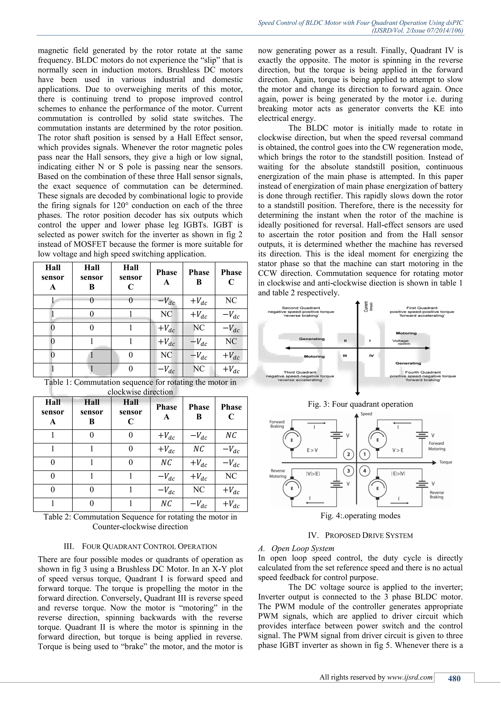
reversal of direction of rotation it implies there is a change
in the quadrant. When the motor is operating in the motoring
mode, in the clockwise direction, the relay contacts are
normally open. But when braking is applied or when a speed
reversal command is received, the relay contacts are closed.
The kinetic energy which will be wasted as heat energy is
now converted into electric energy which is rectified and
stored in a chargeable battery.
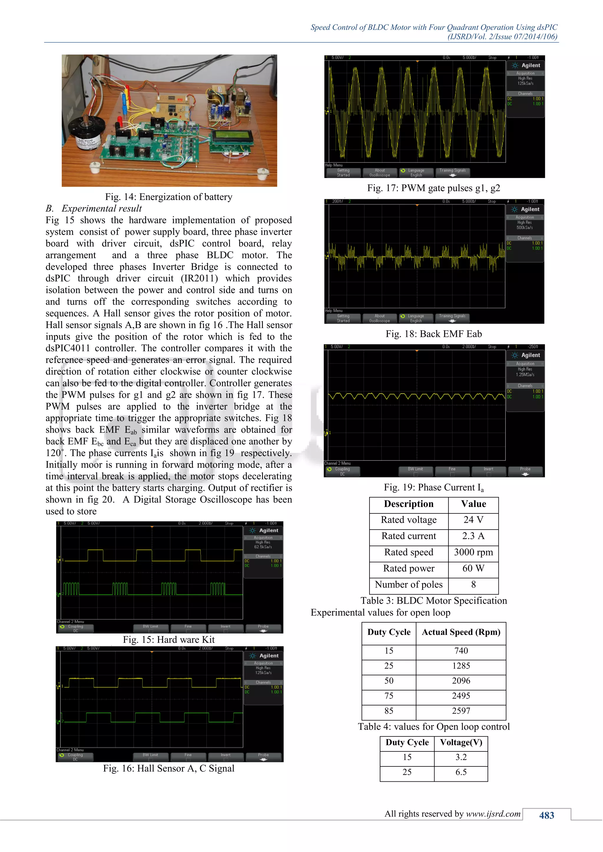
Fig. 5: block diagram of open loop
B. Closed Loop System
The DC voltage source is applied to the inverter; Inverter
output is connected to the 3 phase BLDC motor. The Hall
sensors give the position of the rotor which is fed to the
controller. The controller compares actual speed with the
reference speed and generates an error signal. Depending on
the error signal the PWM module of the controller generates
appropriate PWM signals, and applied to driver circuit
which provides interface between power switch and the
control signal. The PWM signal from driver circuit is given
to three phase IGBT inverter as shown in fig 6.
The position signals obtained from the Hall sensors
of the motor are read by the I/O lines of the dsPIC
controller. Whenever there is a reversal of direction of
rotation it implies there is a change in the quadrant. When
the motor is operating in the motoring mode, in the
clockwise direction, the relay contacts are normally open.
But when braking is applied or when a speed reversal
command is received, the relay contacts are closed. The
kinetic energy which will be wasted as heat energy is now
converted into electric energy which is rectified and stored
in a chargeable battery. The frequent reversal of direction of
rotation will result in the continuous charging of the battery.
The energy thus stored can be used to run the same motor
when there is an interruption of power supply.
Fig. 6: block diagram of closed loop
C. dsPIC Controller
The digital pulse width modulation control of BLDC motor
will be efficient and cost effective. Different types of dsPIC
controllers available like dsPIC30F2011,
dsPIC30F4011/4012. In this paper the digital control of the
four quadrant operation of the three phase BLDC motor is
achieved with dsPIC30F4011. This digital controller
combines the Digital Signal Processor features and
microcontroller features, making it versatile. The
dsPIC30F4011 device contains extensive Digital Signal
Processor (DSP) functionality within high performance 16-
bit microcontroller (MCU) architecture. The PWM module
generates multiple synchronized Pulse width modulation
(PWM) outputs. It has six PWM I/O pins with three duty
cycle generators. The three PWM duty cycle registers are
double buffered to allow updates of PWM outputs. For each
duty cycle, there is a duty cycle register that will be
accessible by the user while the second duty cycle registers
holds the actual compared value used in the present PWM
period. The output compare module generates an interrupt to
trigger the relay circuit during regenerative mode. The
device is programmed in open loop and closed loop using
MPLAB Integrated Development Environment (IDE) tool.
For execution of C-code, MPLAB compiler is used.
D. Relay
The relay circuit is shown in fig 7 whenever there is a
reversal of direction of rotation it implies there is a change
in the quadrant. When the motor is operating in the motoring
mode, in the clockwise direction, the relay contacts are
normally open. But when braking is applied or when a speed
reversal command is received from dsPIC, the relay contacts
are get closed. The K.E which is wasted as heat is rectified
and stored in battery. This energy can be used further when
there is an interruption of power supply.
Fig. 7: Relay
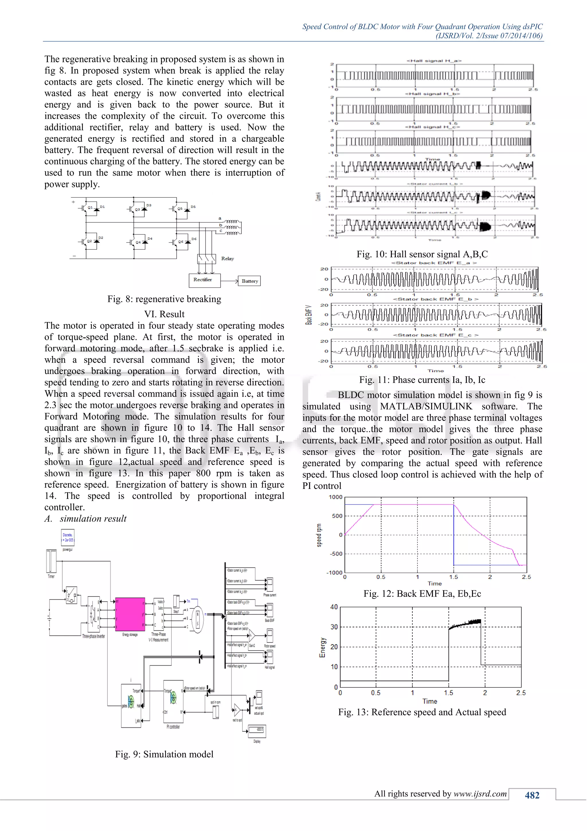
V. REGENERATIVE BRAKING
In locomotives, precise control over stopping of machine is
important along with start. In such a case to stop the
machine quickly and accurately, braking methods are useful.
Braking is nothing but stopping the machine at a desired
position. Braking of locomotive can be done as electric
braking or mechanical braking. In mechanical braking the
motion is restricted by the friction applied by mechanical
brakes which is preferred during low speeds. In electric
braking the motor works as a generator developing a
negative torque which restricts the motion. The purpose of
electrical braking is to restrict the motion of the machine as
quick as possible. In regenerative braking, instead of
wasting the power in external resistance the power
generated during retardation is fed back towards the source
i.e., the motor works as a generator developing a negative
torque which opposes the motion and the generated energy
is supplied to the source. For the generated energy to be
supplied to the source two conditions should be satisfied [4].
(1) Back emf should be greater than supply voltage (E
> V) for all speeds.
(2) Current has to reverse its direction.](https://image.slidesharecdn.com/ijsrdv2i7194-150921123633-lva1-app6891/75/Speed-Control-of-BLDC-Motor-with-Four-Quadrant-Operation-Using-dsPIC-3-2048.jpg)
![Speed Control of BLDC Motor with Four Quadrant Operation Using dsPIC
(IJSRD/Vol. 2/Issue 07/2014/106)
All rights reserved by www.ijsrd.com 484
50 11.8
75 20
Table 5: Generated Voltage during Regenerative Braking
Experimental values for closed loop
Set Speed
(Rpm)
Actual Speed
(Rpm)
300 295
1000 1004
1500 1497
2000 2003
2500 2497
Table 6: Speed Values For Closed Loop
Speed (rpm) Voltage (V)
300 1.8
1000 7.2
1500 11.4
2000 16.7
Table 7: Generated Voltage during Regenerative Braking
VI. CONCLUSION
In this paper a control scheme is proposed for BLDC motor
to change the direction from CW to CCW and the speed
control is achieved. A dsPIC4011 controller is used to
control the speed of the BLDC motor. Speed control is done
in open loop and closed loop by a IGBTs inverter. The
generated voltage during the regenerative mode is stored in
battery which will result in considerable saving of power.
The generated energy can be used to run the motor
whenever there is a power supply failure. This concept may
well be utilized in the rotation of spindles, embroidery
machines, washing machine, fans insmall power application.
In large power application like in industry, electric
locomotive and in satellite where there is frequent reversal
of direction of rotation of the motor taking place.
Advantages of this proposed method are: simple
hardware circuit, excellent speed control, smooth transition
between the quadrants and efficient conservation of energy
during regenerative breaking.
REFERENCES
[1] Wael A. SALAH, Dahaman ISHAK, Khaleel J.
HAMMADI, Soib TAIB “Development of a BLDC
motor drive with improved output
Characteristics”PRZEGLĄD
ELEKTROTECHNICZNY (Electrical Review), ISSN
0033-2097, R. 87 NR 3/2011
[2] Ms. Snehalata Y. Dhenge, Prof. V.S. Nandanwar “To
Study Speed Control and Four Quadrant Operation of
BLDC Motor” International Journal of Engineering
Research and Applications (IJERA) Vol. 3, Issue 2,
March -April 2013, pp.733-737
[3] M.Rakesh, P.V.R.L. Narasimham Department of EEE
“ Different Braking Techniques Employed to a
Brushless DC Motor Drive used in Locomotives”
International Electrical Engineering Journal (IEEJ)
Vol. 3 (2012) No. 2, pp. 784-790 ISSN 2078-2365
[4] Santosh Verma, C. Khare, Sanjay Verma “Modeling
and Simulation of Four Quadrant Operation of
ThreePhase Brushless DC Motor With Hysteresis
Current Controller”International Journal of Advanced
Research in Electrical, Electronics and
Instrumentation Engineering Vol. 2, Issue 6, June
2013
[5] VandanaGovindan T.K, Anish Gopinath TVM
S.Thomas George “DSP based Speed Control of
Permanent Magnet Brushless DC Motor” IJCA Special
Issue on “Computational Science - New Dimensions &
Perspectives”NCCSE, 2011
[6] Vinatha U, Research Scholar, SwethaPola, Asst.
Software Engg., TCS, Dr K.P.Vittal, National Inst. of
Technology “Simulation of Four Quadrant Operation
& Speed Control of BLDC Motor on MATLAB /
SIMULINK” International Journal of Recent Trends
in Engineering, Vol 2, No. 6, November 2009
[7] PadmarajaYedamale, “Brushless DC (BLDC) Motor
Fundamentals”,AN885, Microchip Technology Inc.,
2003.
[8] Anand Sathyan, Mahesh Krishnamurthy, Nikola
Milivojevic& Ali Emadi ”A Low-Cost Digital Control
Scheme for Brushless DC Motor Drives in Domestic
Applications” ,IEEE, 2009](https://image.slidesharecdn.com/ijsrdv2i7194-150921123633-lva1-app6891/75/Speed-Control-of-BLDC-Motor-with-Four-Quadrant-Operation-Using-dsPIC-6-2048.jpg)

The document presents a study on controlling brushless DC (BLDC) motors using a DSPIC controller for four-quadrant operation, focusing on regenerative braking and motor efficiency. It highlights the advantages of BLDC motors over traditional brushed motors, such as higher efficiency and lower maintenance, and describes a system using digital signal processing for precise control. The proposed designs, including simulation and experimental results, demonstrate effective energy conservation and flexibility in motor operation with the ability to store energy during braking.