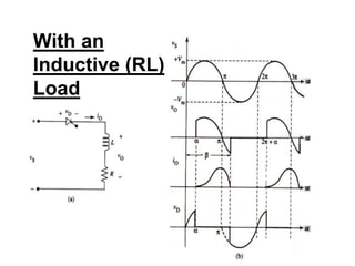
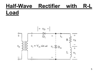
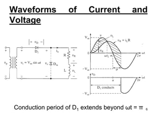
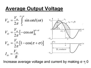
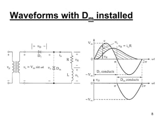
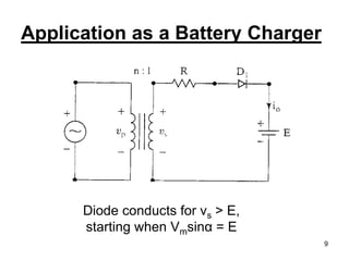
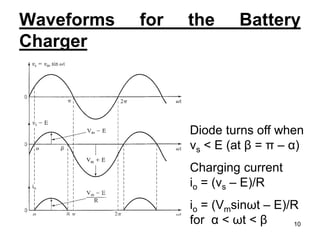
Name :- Smit Shah -140410109096
T.Y Electrical 2 Sem 5
Subject:-Power Electronics-1
Topic :-Half wave control rectifier with RL
load 1
Introduction
 Diodes of rectifier circuits are replaced by thyristors.
 In thyristor based rectifiers, output voltage can be controlled.
So they are termed as controlled rectifiers.
 Controlled rectifiers produce variable DC output, whose
magnitude is varied by Phase control.
Phase Control
DC output from rectifier is controlled by controlling duration of
the conduction period by varying the point at which gate signal
is applied to SCR.
 Main drawback of phase control is Radio Frequency
Interference (RFI)
2
 Controlled rectifiers are of two types,
1- Fully Controlled rectifiers
DC current is unidirectional, but DC voltage has either
polarity. With one polarity, flow of power is from AC
source to DC load---Rectification.
With the reversal of DC voltage by the load, flow of
power is from DC load to AC source---Inversion.
2- Half controlled rectifiers
Half of SCRs are replaced by diodes.
DC output current and voltage are unidirectional. i.e.,
flow of power is from AC source to DC load.
3
With an
Inductive (RL)
Load
4
Half-Wave Rectifier with R-L
Load
5
Waveforms of Current and
Voltage
Conduction period of D1 extends beyond ωt = π 6
Average Output Voltage
 
 
0
0
sin ( )
2
cos
2
1 cos( )
2
m
dc
m
dc
m
dc
dc
dc
V
V td t
V
V t
V
V
V
I
R
 
 
 



 




 
  


Increase average voltage and current by making σ = 07
Waveforms with Dm installed
8
Application as a Battery Charger
Diode conducts for vs > E,
starting when Vmsinα = E
9
Waveforms for the Battery
Charger
Diode turns off when
vs < E (at β = π – α)
Charging current
io = (vs – E)/R
io = (Vmsinωt – E)/R
for α < ωt < β 10
11

Half wave control rectifier with RL load

  • 1.
    Name :- SmitShah -140410109096 T.Y Electrical 2 Sem 5 Subject:-Power Electronics-1 Topic :-Half wave control rectifier with RL load 1
  • 2.
    Introduction  Diodes ofrectifier circuits are replaced by thyristors.  In thyristor based rectifiers, output voltage can be controlled. So they are termed as controlled rectifiers.  Controlled rectifiers produce variable DC output, whose magnitude is varied by Phase control. Phase Control DC output from rectifier is controlled by controlling duration of the conduction period by varying the point at which gate signal is applied to SCR.  Main drawback of phase control is Radio Frequency Interference (RFI) 2
  • 3.
     Controlled rectifiersare of two types, 1- Fully Controlled rectifiers DC current is unidirectional, but DC voltage has either polarity. With one polarity, flow of power is from AC source to DC load---Rectification. With the reversal of DC voltage by the load, flow of power is from DC load to AC source---Inversion. 2- Half controlled rectifiers Half of SCRs are replaced by diodes. DC output current and voltage are unidirectional. i.e., flow of power is from AC source to DC load. 3
  • 4.
  • 5.
  • 6.
    Waveforms of Currentand Voltage Conduction period of D1 extends beyond ωt = π 6
  • 7.
    Average Output Voltage    0 0 sin ( ) 2 cos 2 1 cos( ) 2 m dc m dc m dc dc dc V V td t V V t V V V I R                       Increase average voltage and current by making σ = 07
  • 8.
    Waveforms with Dminstalled 8
  • 9.
    Application as aBattery Charger Diode conducts for vs > E, starting when Vmsinα = E 9
  • 10.
    Waveforms for theBattery Charger Diode turns off when vs < E (at β = π – α) Charging current io = (vs – E)/R io = (Vmsinωt – E)/R for α < ωt < β 10
  • 11.