This document provides an overview of brushless DC motors. It discusses their structure, drive circuits, equivalent circuit model, and performance characteristics. Brushless DC motors have a rotor with permanent magnets and stator windings similar to AC motors. They use electronic commutation instead of brushes and commutators, making them maintenance-free. The document covers various drive circuit topologies including unipolar and bipolar drives. It also presents the dynamic and steady-state equivalent circuits and performance equations of brushless DC motors.
![Chapter 12. Brushless DC Motors
Topics to cover:
1. Structures and Drive Circuits
2. Equivalent Circuit
3. Performance
4. Applications
Introduction
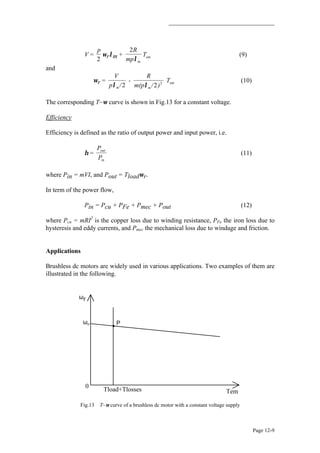
Conventional dc motors are highly efficient and their characteristics make them suitable
for use as servomotors. However, their only drawback is that they need a commutator
and brushes which are subject to wear and require maintenance. When the functions of
commutator and brushes were implemented by solid-state switches, maintenance-free
motors were realised. These motors are now known as brushless dc motors.
In this chapter, the basic structures, drive circuits, fundamental principles, steady state
characteristics, and applications of brushless dc motors will be discussed.
Structures and Drive Circuits
Basic structures
The construction of modern brushless motors is very similar to the ac motor, known as
the permanent magnet synchronous motor. Fig.1 illustrates the structure of a typical
three-phase brushless dc motor. The stator windings are similar to those in a polyphase
ac motor, and the rotor is composed of one or more permanent magnets. Brushless dc
motors are different from ac synchronous motors in that the former incorporates some
means to detect the rotor position (or magnetic poles) to produce signals to control the
electronic switches as shown in Fig.2. The most common position/pole sensor is the
Hall element, but some motors use optical sensors.
Fig.1 Disassembled view of a brushless dc motor (from Ref.[1] p58 Fig.4.1)](https://image.slidesharecdn.com/2-150820050610-lva1-app6891/85/2-brushless-dc-motors-1-320.jpg)
![48531 EMS – Chapter 12. Brushless DC Motors
Page 12-2
Logic
Circuit
DC
Supply
PM ac
Motor
Position
Sensor
Electronic Commutator
Fig.2 Brushless dc motor = Permanent magnet ac motor + Electronic commutator
Although the most orthodox and efficient motors are three-phase, two-phase brushless
dc motors are also very commonly used for the simple construction and drive circuits.
Fig.3 shows the cross section of a two-phase motor having auxiliary salient poles.
Comparison of conventional and brushless dc motors
Although it is said that brushless dc motors and conventional
dc motors are similar in their static characteristics, they
actually have remarkable differences in some aspects. When
we compare both motors in terms of present-day technology,
a discussion of their differences rather than their similarities
can be more helpful in understanding their proper
applications. Table 1 compares the advantages and
disadvantages of these two types of motors. When we
discuss the functions of electrical motors, we should not
forget the significance of windings and commutation.
Commutation refers to the process which converts the input direct current to alternating
current and properly distributes it to each winding in the armature. In a conventional dc
motor, commutation is undertaken by brushes and commutator; in contrast, in a
brushless dc motor it is done by using semiconductor devices such as transistors.
Fig.3 Two-phase motor
having auxiliary salient poles
(from Ref.[1] p95 Fig.5.22)](https://image.slidesharecdn.com/2-150820050610-lva1-app6891/85/2-brushless-dc-motors-2-320.jpg)
![48531 EMS – Chapter 12. Brushless DC Motors
Page 12-3
Drive circuits
(1) Unipolar drive
Fig.4 illustrates a simple three-phase unipolar-operated motor that uses optical sensors
(phototransistors) as position detectors. Three phototransistors PT1, PT2, and PT3 are
placed on the end-plate at 120
o
intervals, and are exposed to light in sequence through a
revolving shutter coupled to the motor shaft.
As shown in Fig.4, the north pole of the rotor now faces the salient pole P2 of the stator,
and the phototransistor PT1 detects the light and turns transistor Tr1 on. In this state, the
south pole which is created at the salient pole P1 by the electrical current flowing
through the winding W1 is attracting the north pole of the rotor to move it in the
direction of the arrow. When the north pole comes to the position to face the salient pole
P1, the shutter, which is coupled to the shaft, will shade PT1, and PT2 will be exposed
to the light and a current will flow through the transistor Tr2. When a current flows
through the winding W2, and creates a south pole on salient pole P2, then the north pole
in the rotor will revolve in the direction of the arrow and face the salient pole P2. At this
moment, the shutter shades PT2, and the phototransistor PT3 is exposed to the light.
These actions steer the current from the winding W2 to W3. Thus salient pole P2 is de-
energized, while the salient pole P3 is energized and creates the south pole. Hence the
north pole on the rotor further travels from P2 to P3 without stopping. By repeating such
a switching action in sequence given in Fig.5, the permanent magnet rotor revolves
continuously.
Fig.4 Three-phase unipolar-driven brushless dc motor
(from Ref.[1] p59 Fig.4.2 with winding directions swapped)](https://image.slidesharecdn.com/2-150820050610-lva1-app6891/85/2-brushless-dc-motors-3-320.jpg)
![48531 EMS – Chapter 12. Brushless DC Motors
Page 12-4
Fig.5 Switching sequence and rotation of stator's magnetic field
(from Ref.[1] p60 Fig.4.3)
(2) Bipolar drive
When a three-phase (brushless) motor is driven by a three-phase bridge circuit, the
efficiency, which is the ratio of the mechanical output power to the electrical input
power, is the highest, since in this drive an alternating current flows through each
winding as an ac motor. This drive is often referred to as 'bipolar drive'. Here, 'bipolar'
means that a winding is alternatively energised in the south and north poles.
We shall now survey the principle of the three-phase bridge circuit of Fig.6. Here too,
we use the optical method for detecting the rotor position; six phototransistors are
placed on the end-plate at equal intervals. Since a shutter is coupled to the shaft, these
photo elements are exposed in sequence to the light emitted from a lamp placed in the
left of the figure. Now the problem is the relation between the ON/OFF state of the
transistors and the light detecting phototransistors. The simplest relation is set when the
logic sequencer is arranged in such a way that when a phototransistor marked with a
certain number is exposed to light, the transistor of the same number turns ON. Fig.6
shows that electrical currents flow through Tr1, Tr4, and Tr5, and terminals U and W
have the battery voltage, while terminal V has zero potential. In this state, a current will
flow from terminal U to V, and another current from W to V as illustrated in Fig.7. We
may assume that the solid arrows in this figure indicate the directions of the magnetic
fields generated by the currents in each phase. The fat arrow in the centre is the resultant
magnetic field in the stator.](https://image.slidesharecdn.com/2-150820050610-lva1-app6891/85/2-brushless-dc-motors-4-320.jpg)
![48531 EMS – Chapter 12. Brushless DC Motors
Page 12-5
Fig.6 Three phase bipolar-driven brushless motor (from Ref.[1] p61, Fig.4.4)
The rotor is placed in such a position that the field flux will have a 90
o
angle with
respect to the stator's magnetic field as shown in Fig.7. In such a state a clockwise
torque will be produced on the rotor. After it revolves through about 30o
, PT5 is turned
OFF and PT6 ON which makes the stator's magnetic pole revolve 60
o
clockwise. Thus
when the rotor's south pole gets near, the stator's south pole goes away further to create a
continuous clockwise rotation. The ON-OFF sequence and the rotation of the transistor
are shown in Fig.8.
Fig.7 Stator's magnetic field in the shutter state of Fig.6, and the direction
of torque (from Ref.[1] p62, Fig.4.5)
Fig.8 Clockwise revolutions of the stator's magnetic field and rotor
(from Ref.[1] p63 Fig.4.6)](https://image.slidesharecdn.com/2-150820050610-lva1-app6891/85/2-brushless-dc-motors-5-320.jpg)
![48531 EMS – Chapter 12. Brushless DC Motors
Page 12-6
The rotational direction may be reversed by arranging the logic sequencer in such a way
that when a photodetector marked with a certain number is exposed to light, the
transistor of the same number is turned OFF. On the other hand, when a phototransistor
is not exposed to light, the transistor of the same number is turned ON.
In the positional state of Fig.6, Tr2, 3, and 6 are ON, and the battery voltage E appears at
terminal V, while U and W have zero electric potential. Then, as shown in Fig.9(a), the
magnetic field in the stator is reversed, and the rotor's torque is counter-clockwise. After
the motor revolves about 30
o
, Tr2 turns OFF and Tr1 ON. At this point, the field has
revolved 60
o
and becomes as shown in (b). As the rotor produces another counter-
clockwise torque, the counter-clockwise motion continues and the field becomes as
shown in (c). This action is replaced in the sequence of (a)→(b)→(c)→(d)...... to
produce a continuous counter-clockwise motion.
Fig.9 Counter-clockwise revolutions of the stator's magnetic field and rotor (from Ref.[1] p63 Fig.4.7)
The motor discussed above has ∆-connected windings, but it may also have Y-
connected windings. Fig.10(a) shows a practical circuit which is used in a laser-beam
printer or a hard-disc drive. As shown in Fig.10(b), three Hall elements are placed at
intervals of 60
o
for detection of the rotor's magnetic poles. Because this motor has four
magnetic poles, a mechanical angle of 60
o
corresponds to an electrical angle of 120
o
.
Equivalent Circuit and General Equations
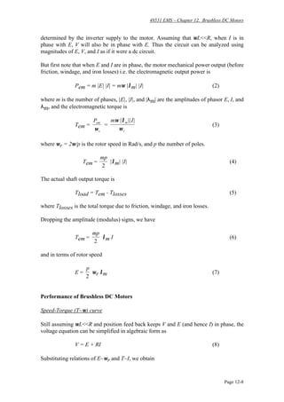
The per phase equivalent circuit is shown in Fig.11 as following, where λm is the flux
linkage of stator winding per phase due to the permanent magnet.
For steady state conditions, assuming v and e are sinusoidal at frequency ω, the
equivalent circuit becomes the one shown in Fig.12, where X=ωL, and V, I, E, and λm
are phasors with rms amplitudes. The steady state circuit equation can be written as
V = E + ( R + jωL ) I (1)](https://image.slidesharecdn.com/2-150820050610-lva1-app6891/85/2-brushless-dc-motors-6-320.jpg)
![48531 EMS – Chapter 12. Brushless DC Motors
Page 12-7
Fig.10 Practical circuit for a three-phase bipolar-driven motor, and
arrangement of Hall elements (from Ref.[1] p80 Fig.5.1)
e =
dλ
dt
m
v
i
L R
Fig.11 Dynamic per phase equivalent circuit of brushless dc motors
V
I
RX = ωL
E = jωλ m
Fig.12 Steady state per phase equivalent circuit of brushless dc motors
For a maximum mechanical power at a given speed, I and E are in phase. This also gives
maximum torque/ampere (minimum current/Nm). A brushless dc motor has position
feedback from the rotor via Hall devices, optical devices, encoder etc. to keep a
particular angle between V and E, since E is in phase with rotor position, and V is](https://image.slidesharecdn.com/2-150820050610-lva1-app6891/85/2-brushless-dc-motors-7-320.jpg)
![48531 EMS – Chapter 12. Brushless DC Motors
Page 12-10
Laser printer
In a laser printer, a polygon mirror is coupled directly to the motor shaft and its speed is
controlled very accurately in the range from 5000 to 40,000 rpm. When an intensity-
modulated laser beam strikes the revolving polygon mirror, the reflected beam travels in
different direction according to the position of the rotor at that moment. Therefore, this
reflected beam can be used for scanning as shown in Fig.14. How an image is produced
is explained, using Fig.15 and the following statements:
(1) The drum has a photoconductive layer (e.g. Cds) on its surface, with photosensitivity
of the layer being tuned to the wavelength of the laser. The latent image of the
information to be printed formed on the drum surface by the laser and then developed by
the attracted toner.
(2) The developed image is then transferred to normal paper and fixed using heat and
pressure.
(3) The latent image is eliminated.
A recent brushless dc motor designed for a laser printer is shown in Fig.16, and its
characteristic data are given in Table 2.
Fig.14 Role of motors for laser printers; (right) a brushless dc motor driving a polygon mirror, and
(above) how to scan laser beams (from Ref.[1] p82 Fig.5.3)](https://image.slidesharecdn.com/2-150820050610-lva1-app6891/85/2-brushless-dc-motors-10-320.jpg)
![48531 EMS – Chapter 12. Brushless DC Motors
Page 12-11
Fig.15 Principles of laser printers (from Ref.[1] p82 Fig.5.4)
Fig.16 Brushless dc motor for a laser printer (from Ref.[1] p83 Fig.5.5
Table 2 Characteristics of three-phase bipolar type brushless motors
* A non-inertial load is a load applied by using a pulley and a weight](https://image.slidesharecdn.com/2-150820050610-lva1-app6891/85/2-brushless-dc-motors-11-320.jpg)
![48531 EMS – Chapter 12. Brushless DC Motors
Page 12-12
Hard disk drive
As the main secondary memory device of the computer, hard disks provide a far greater
information storage capacity and shorter access time than either a magnetic tape or
floppy disk. Formerly, ac synchronous motors were used as the spindle motor in floppy
or hard disk drives. However, brushless dc motors which are smaller and more efficient
have been developed for this application and have contributed to miniaturization and
increase in memory capacity in computer systems. Table 3 compares a typical ac
synchronous motor with a brushless dc motor when they are used as the spindle motor in
an 8-inch hard disk drive. As is obvious from the table, the brushless dc motor is far
superior to the ac synchronous motor. Although the brushless dc motor is a little
complicated structurally because of the Hall elements or ICs mounted on the stator, and
its circuit costs, the merits of the brushless dc motor far outweigh the drawbacks.
Table 3 Comparison of an ac synchronous motor and a brushless dc motor for an 8-inch hard disk drive
Fig.17 An example of hard disk drive (single disk type) (from Ref.[1] p86 Fig.5.9)](https://image.slidesharecdn.com/2-150820050610-lva1-app6891/85/2-brushless-dc-motors-12-320.jpg)
![48531 EMS – Chapter 12. Brushless DC Motors
Page 12-13
The hard disk drive works as follows (see Fig.17): The surface of the aluminium disk is
coated with a film of magnetic material. Data is read/written by a magnetic head floating
at a distance of about 0.5 µm from the disk surface due to the airflow caused by the
rotating disk, and this maintains a constant gap. Therefore, when the disk is stopped or
slowed down, the head may touch the disk and cause damage to the magnetic film. To
prevent this, this spindle motor must satisfy strict conditions when starting the stopping.
Table 4 lists the basic characteristic data of brushless dc motors used in 8-inch hard disk
drives (Fig.18).
Table 4 Characteristics of a three-phase unipolar motor designed for the spindle drive in
a hard disk drive (from Ref.[1] p87 Table 5.3)
Fig.18 A brushless dc motor used for 8-inch hard disk drives (from Ref.[1] p87 Fig.5.10)
REFERENCES
[1] T. Kenjo, "Permanent magnet and brushless dc motors", Oxford, 1985
[2] T.J.E. Miller, "Brushless permanent magnet and reluctance motor drive", Oxford, 1989](https://image.slidesharecdn.com/2-150820050610-lva1-app6891/85/2-brushless-dc-motors-13-320.jpg)