Outline
Machine Locationand Addresses
Memory Operations
Instructions and Instruction
Sequencing
Addressing Modes
Assembly Language
Basic Input and Output Operations
3.
Memory Locations andAddresses
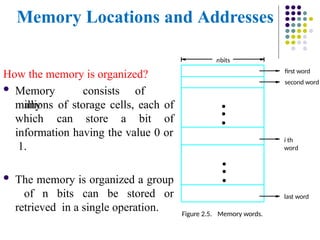
How the memory is organized?
Memory consists of
many
millions of storage cells, each of
which can store a bit of
information having the value 0 or
1.
The memory is organized a group
of n bits can be stored or
retrieved in a single operation.
first word
second word
Figure 2.5. Memory words.
nbits
last word
i th
word
•
•
•
•
•
•
4.
Memory Locations andAddresses
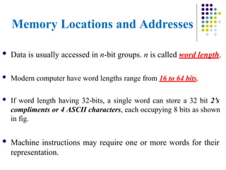
Data is usually accessed in n-bit groups. n is called word length.
Modern computer have word lengths range from 16 to 64 bits.
If word length having 32-bits, a single word can store a 32 bit 2’s
compliments or 4 ASCII characters, each occupying 8 bits as shown
in fig.
Machine instructions may require one or more words for their
representation.
5.
Memory Locations andAddresses
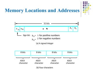
(b) Four characters
ASCII
character
ASCII
character
ASCII
character
ASCII
character
(a) A signed integer
Sign bit: 1 for positive numbers
2 for negative numbers
32 bits
8 bits 8 bits 8 bits 8 bits
b31=
b31=
•
b 31
b30
•
•
b1 b0
6.
Memory Locations andAddresses
To retrieve information from memory, either for one word or one byte
(8-bit), addresses for each location are needed.
A k-bit address memory has 2k memory locations using numbers from
0 – 2k-1 as the addresses of successive locations in the memory.
2k addresses constitute the address space of the computer and
the
memory can have up to 2k addressable locations.
For Ex:
24-bit memory: 224 = 16,777,216 = 16M (1M=220)
32-bit memory: 232 = 4G (1G=230)
1K(kilo)=210 and 1T(tera)=240
7.
Memory Locations andAddresses
Byte Addressability
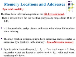
The three basic information quantities are bit, byte and word.
Byte is always 8 bits but the word length typically ranges from 16 to 64
bits.
It is impractical to assign distinct addresses to individual bit locations
in the memory.
The most practical assignment is to have successive addresses refer to
successive byte locations in the memory – byte-addressable memory.
Byte locations have addresses 0, 1, 2, … If the word length is 32 bits,
successive words are located at addresses 0, 4, 8,… with each word
consisting of 4 bytes.
8.
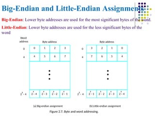
Big-Endian and Little-EndianAssignments
0 1 2 3
4 5 6 7
•
•
•
k
2 - 4
k
2 - 3
k
2 - 2
k
2 - 1
k
2 - 4
k
2 - 4
0
0
4
3 2 1 0
7 6 5 4
•
•
•
k
2 - 1
k
2 - 2
k
2 - 3
k
2 - 4
Byte address
Byte address
(a) Big-endian assignment (b) Little-endian assignment
Figure 2.7. Byte and word addressing.
4
Word
address
Big-Endian: Lower byte addresses are used for the most significant bytes of the word.
Little-Endian: Lower byte addresses are used for the less significant bytes of the
word
9.
Big-Endian and Little-EndianAssignments
The words More significant and Less significant are used in relation to
the weights(power of 2) assigned to bits when the word represents a
number.
10.
Memory Locations andAddresses
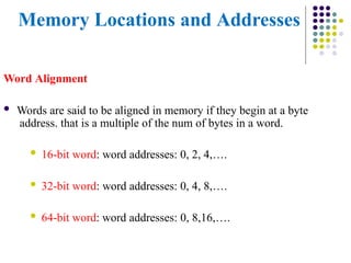
Word Alignment
Words are said to be aligned in memory if they begin at a byte
address. that is a multiple of the num of bytes in a word.
16-bit word: word addresses: 0, 2, 4,….
32-bit word: word addresses: 0, 4, 8,….
64-bit word: word addresses: 0, 8,16,….
11.
Memory Locations andAddresses
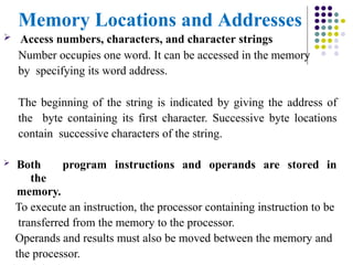
Access numbers, characters, and character strings
Number occupies one word. It can be accessed in the memory
by specifying its word address.
The beginning of the string is indicated by giving the address of
the byte containing its first character. Successive byte locations
contain successive characters of the string.
Both program instructions and operands are stored in
the
memory.
To execute an instruction, the processor containing instruction to be
transferred from the memory to the processor.
Operands and results must also be moved between the memory and
the processor.
12.
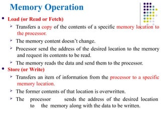
Memory Operation
Load(or Read or Fetch)
Transfers a copy of the contents of a specific memory location to
the processor.
The memory content doesn’t change.
Processor send the address of the desired location to the memory
and request its contents to be read.
The memory reads the data and send them to the processor.
Store (or Write)
Transfers an item of information from the processor to a specific
memory location.
The former contents of that location is overwritten.
The processor sends the address of the desired location
to the memory along with the data to be written.
13.
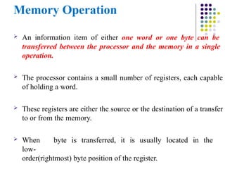
Memory Operation
Aninformation item of either one word or one byte can be
transferred between the processor and the memory in a single
operation.
The processor contains a small number of registers, each capable
of holding a word.
These registers are either the source or the destination of a transfer
to or from the memory.
When byte is transferred, it is usually located in the
low-
order(rightmost) byte position of the register.
14.
Instruction and InstructionSequencing
“Must-Perform” Operations
4 types of operations.
Data transfers between the memory
and the processor registers.
Arithmetic and logic operations on data.
Program sequencing and control.
I/O transfers.
15.
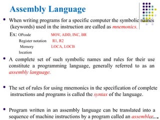
Assembly Language
Whenwriting programs for a specific computer the symbolic names
(keywords) used in the instruction are called as mnemonics.
Ex: OPcode
Register notation
Memory
location
MOV, ADD, INC, BR
R1, R2
LOCA, LOCB
A complete set of such symbolic names and rules for their use
constitute a programming language, generally referred to as an
assembly language.
The set of rules for using mnemonics in the specification of complete
instructions and programs is called the syntax of the language.
Program written in an assembly language can be translated into a
sequence of machine instructions by a program called an assembler.
16.
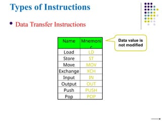
Types of Instructions
Data Transfer Instructions
Name Mnemoni
c
Load LD
Store ST
Move MOV
Exchange XCH
Input IN
Output OUT
Push PUSH
Pop POP
Data value is
not modified
17.
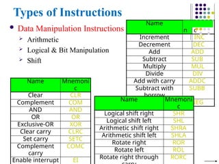
Name M
n
emoni
c
Increment INC
DecrementDEC
Add ADD
Subtract SUB
Multiply MUL
Divide DIV
Add with carry ADDC
Subtract with
borrow
SUBB
Negate NEG
Types of Instructions
Data Manipulation Instructions
Arithmetic
Logical & Bit Manipulation
Shift
Name Mnemoni
c
Clear CLR
Complement COM
AND AND
OR OR
Exclusive-OR XOR
Clear carry CLRC
Set carry SETC
Complement
carry
COMC
Enable interrupt EI
Name Mnemoni
c
Logical shift right SHR
Logical shift left SHL
Arithmetic shift right SHRA
Arithmetic shift left SHLA
Rotate right ROR
Rotate left ROL
Rotate right through RORC
18.
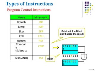
Types of Instructions
ProgramControl Instructions
Name Mnemonic
Branch BR
Jump JMP
Skip SKP
Call CALL
Return RET
Compar
e
(Subtract
)
CMP
Test (AND) TST
Subtract A – B but
don’t store the result
1 0 1 1 0 0 0
1
0 0 0 0 1 0 0 0
0 0 0 0 0 0 0
0
Mask
19.
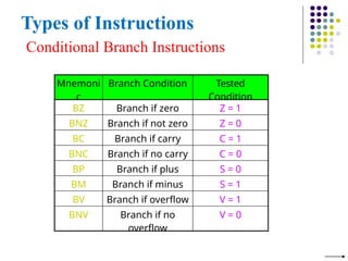
Types of Instructions
ConditionalBranch Instructions
Mnemoni
c
Branch Condition Tested
Condition
BZ Branch if zero Z = 1
BNZ Branch if not zero Z = 0
BC Branch if carry C = 1
BNC Branch if no carry C = 0
BP Branch if plus S = 0
BM Branch if minus S = 1
BV Branch if overflow V = 1
BNV Branch if no
overflow
V = 0
20.
Register Transfer Notation
Identify a location by a symbolic name standing for its
hardware binary address
Ex: For address of memory location: LOC,PLACE,A,VAR2
For processor registers: R0,R1
For I/O registers: DATAIN, OUTSTATUS
Contents of a location are denoted by placing square brackets around
the name of the location
Ex: R1←[LOC] ----The contents of memory location LOC are
transferred into processor register R1
R3 ←[R1]+[R2]
This type of notation is known as Register Transfer Notation (RTN)
21.
Assembly Language Notation
To represent machine instructions and programs.
Ex: Move LOC, R1 ;R1←[LOC] Add R1,
R2, R3 ;R3 ←[R1]+[R2]
Basic Instruction Types
Example:Evaluate E=(A+B) (C+D)
One-Address
LOAD
A
; AC ← M[A]
; AC ← AC + M[B]
; R1 ← AC
; AC ← M[C]
; AC ← AC + M[D]
; AC ← AC R1
; M[E] ← AC
ADD B
STORE R1
LOAD C
ADD D
MUL R1
STORE E
27.
Using Registers
Registersare faster
Shorter instructions
Potential speedup
Minimize the frequency with which data is moved back
and forth between the memory and processor registers.
28.
Using Registers
Itis necessary to transfer data between different locations. This is
achieved with the instruction
Move Source, Destination
Which places a copy of the contents of Source into Destination.
The Move instruction can be used rather than Load or Store
instructions because the order of the Source and Destination operands
determines which operation is intended. Thus
Move A, Ri
Is the same as
Load A, Ri
And
Move Ri, A
Is the same as
Store Ri, A
29.
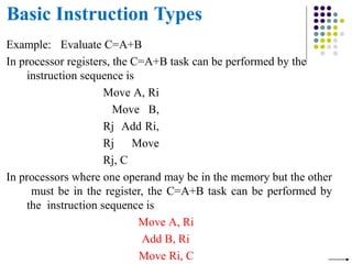
Basic Instruction Types
Example:Evaluate C=A+B
In processor registers, the C=A+B task can be performed by the
instruction sequence is
Move A, Ri
Move B,
Rj Add Ri,
Rj Move
Rj, C
In processors where one operand may be in the memory but the other
must be in the register, the C=A+B task can be performed by
the instruction sequence is
Move A, Ri
Add B, Ri
Move Ri, C
30.
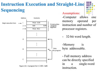
Instruction Execution andStraight-Line
Sequencing
Move A,R0
Add B,R0
Move R0,C
i
i + 4
i + 8
Begin execution here
Contents
Address
C
B
A
the program
Data
for
3-instruction
program
segment
Figure 2.8. A program for C +
Assumptions:
memory operand
-Computer allows one
per
instruction and number of
processor registers.
- 32-bit word length.
-Memory is
byte addressable.
- Full memory address
can be directly specified
in a single-word
instruction.
31.
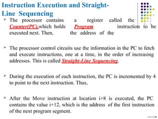
Instruction Execution andStraight-
Line Sequencing
The processor contains
Counter(PC),which holds
executed next. Then,
a register called the
Program
the address of the
instruction to be
The processor control circuits use the information in the PC to fetch
and execute instructions, one at a time, in the order of increasing
addresses. This is called Straight-Line Sequencing.
During the execution of each instruction, the PC is incremented by 4
to point to the next instruction. Thus,
After the Move instruction at location i+8 is executed, the PC
contains the value i+12, which is the address of the first instruction
of the next program segment.
32.
Instruction Execution andStraight-
Line Sequencing
Straight line sequencing is Two-phase procedure
- Instruction fetch
and
- Instruction execute
33.
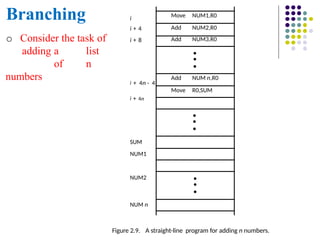
Branching
NUM n
Figure 2.9.A straight-line program for adding n numbers.
SUM
NUM1
NUM2
Move NUM1,R0
Add NUM2,R0
Add NUM3,R0
•
•
•
Add NUM n,R0
Move R0,SUM
•
•
•
•
•
•
i
i + 4
i + 8
i + 4n - 4
i + 4n
o Consider the task of
adding a list
of n
numbers
34.
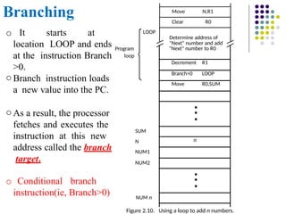
Branching N,R1
Move
NUM n
NUM2
NUM1
Figure2.10. Using a loop to add n numbers.
LOOP
Program
loop
Clear R0
Determine address of
"Next" number and add
"Next" number to R0
Decrement R1
Branch>0 LOOP
Move R0,SUM
•
•
•
n
•
•
•
N
SUM
o It starts at
location LOOP and ends
at the instruction Branch
>0.
o Branch instruction loads
a new value into the PC.
o As a result, the processor
fetches and executes the
instruction at this new
address called the branch
target.
o Conditional branch
instruction(ie, Branch>0)
35.
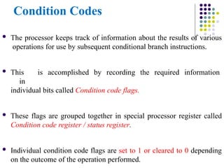
Condition Codes
Theprocessor keeps track of information about the results of various
operations for use by subsequent conditional branch instructions.
This is accomplished by recording the required information
in
individual bits called Condition code flags.
These flags are grouped together in special processor register called
Condition code register / status register.
Individual condition code flags are set to 1 or cleared to 0 depending
on the outcome of the operation performed.
36.
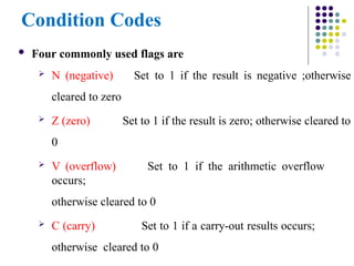
Condition Codes
Fourcommonly used flags are
N (negative)
cleared to zero
Z (zero)
0
Set to 1 if the result is negative ;otherwise
Set to 1 if the result is zero; otherwise cleared to
V (overflow) Set to 1 if the arithmetic overflow
occurs;
otherwise cleared to 0
C (carry) Set to 1 if a carry-out results occurs;
otherwise cleared to 0
37.
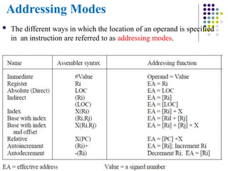
Addressing Modes
Thedifferent ways in which the location of an operand is specified
in an instruction are referred to as addressing modes.
38.
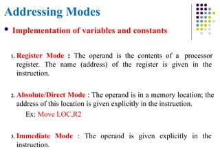
Addressing Modes
Implementationof variables and constants
1. Register Mode : The operand is the contents of a processor
register. The name (address) of the register is given in the
instruction.
2. Absolute/Direct Mode : The operand is in a memory location; the
address of this location is given explicitly in the instruction.
Ex: Move LOC,R2
3. Immediate Mode : The operand is given explicitly in the
instruction.
39.
Addressing Modes
Ex: Move200immediate ,R0 [or] Move
#200,R0 Place the value 200 in register R0.
The Immediate mode is only used to specify the value of a source
operand.
Constant values are used in HLL programs.
Ex: A=B+6
Assuming that A & B have been declared as variables and may be
accessed using the absolute mode. This statement may be compiled
as follows.
Move B,R1
Add #6,R1
Move R1,A
40.
Addressing Modes
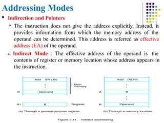
Indirectionand Pointers
The instruction does not give the address explicitly. Instead, it
provides information from which the memory address of the
operand can be determined. This address is referred as effective
address (EA) of the operand.
4. Indirect Mode : The effective address of the operand is the
contents of register or memory location whose address appears in
the instruction.
41.
Addressing Modes
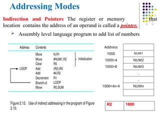
Indirection andPointers The register or memory
location contains the address of an operand is called a pointer.
Assembly level language program to add list of numbers
that
Address
1000 NUM1
1000+4 NUM2
1000+8 NUM3
.
.
1000+4n-4 NUMn
R2 1000
42.
Addressing Modes
Indexingand Arrays
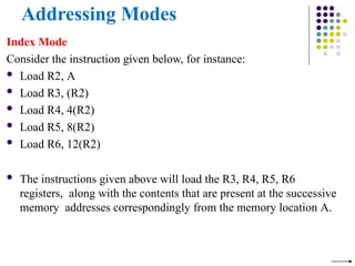
5. Index Mode : The EA of the operand
is generated by adding a constant value to the
contents of a register (index register).
The register may be either a special or
may be any one of general purpose registers in a
processor.
Ex: X(Ri) ; where X=constant value contained in the instruction.
Ri=name of the register involved.
The EA of the operand is given by EA = [Ri] + X
The contents of the index register is not changed in the process of
generating the effective address.
43.
Addressing Modes
Index Mode
Considerthe instruction given below, for instance:
Load R2, A
Load R3, (R2)
Load R4, 4(R2)
Load R5, 8(R2)
Load R6, 12(R2)
The instructions given above will load the R3, R4, R5, R6
registers, along with the contents that are present at the successive
memory addresses correspondingly from the memory location A.
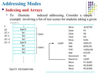
Addressing Modes
Indexingand Arrays
To illustrate indexed addressing, Consider a simple
example involving a list of test scores for students taking a given
course.
46.
Addressing Modes
Indexingand Arrays
6. Base with Index : The effective address is the sum of the contents
of registers Ri and Rj. The second register is usually called as base
register.
Ex: (Ri,Rj) ;EA = [Ri] + [Rj]
7. Base with index and Offset : The effective address is the sum of
the constant X and the contents of registers Ri and Rj.
Ex: X(Ri,Rj) ;EA = [Ri] + [Rj] + X
47.
Addressing Modes
RelativeAddressing
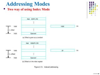
8. Relative mode: The EA is determined by the index mode
using
the PC in place of the general purpose register Ri.
Ex: X(PC) ;EA= [PC] + X
This mode can be used to access data operands.
Commonly used to specify target address in branch instruction.
Branch>0 LOOP
This location is computed by specifying it as an offset from the
current value of PC.
Branch target may be either before or after the branch instruction,
the offset is given as a singed num.
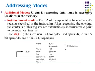
48.
Addressing Modes
AdditionalModes: Useful for accessing data items in successive
locations in the memory.
9. Autoincrement mode – The EA of the operand is the contents of a
register specified in the instruction. After accessing the operand,
the contents of this register are automatically incremented to point
to the next item in a list.
Ex: (Ri)+ ;The increment is 1 for byte-sized operands, 2 for 16-
bit operands, and 4 for 32-bit operands.
N,R1
#NUM1,R2
R0
(R2)+,R0
R1
LOOP
R0,SUM
Move
Move
Clear
Add
Decrement
Branch>0
Move
Initialization
LOOP
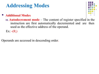
49.
Addressing Modes
AdditionalModes
10. Autodecrement mode – The content of register specified in the
instruction are first automatically decremented and are then
used as the effective address of the operand.
Ex: -(Ri)
Operands are accessed in descending order.
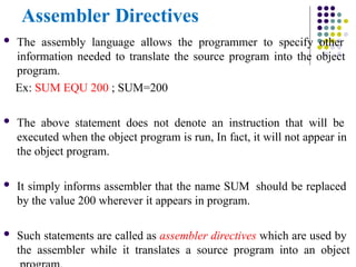
50.
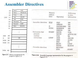
Assembler Directives
Theassembly language allows the programmer to specify other
information needed to translate the source program into the object
program.
Ex: SUM EQU 200 ; SUM=200
The above statement does not denote an instruction that will be
executed when the object program is run, In fact, it will not appear in
the object program.
It simply informs assembler that the name SUM should be replaced
by the value 200 wherever it appears in program.
Such statements are called as assembler directives which are used by
the assembler while it translates a source program into an object
Assembler Directives
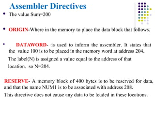
Thevalue Sum=200
ORIGIN-Where in the memory to place the data block that follows.
DATAWORD- is used to inform the assembler. It states that
the value 100 is to be placed in the memory word at address 204.
The label(N) is assigned a value equal to the address of that
location. so N=204.
RESERVE- A memory block of 400 bytes is to be reserved for data,
and that the name NUM1 is to be associated with address 208.
This directive does not cause any data to be loaded in these locations.
53.
Assembler Directives
Second ORIGIN-The instruction of the object program are to
be loaded in the memory starting at address 100.
END- End of source program text.
And it is followed by the text START. Which is the address of
the location at which execution of the program is to begin.
54.
Assembler Directives
Ina source program to be written in the
formLabel Operation Operand(s) Comment
Label – is optional name associated with the memory address where the
machine language instruction produced from the statement will be
loaded.
Ex- SUM, N, NUM1, START, and LOOP
Operation– Contains the OP-Code mnemonic of the desired instruction
or assembler directive.
Operand- Contains address information for accessing one or
more operands depending on the type of information.
55.
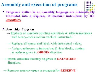
Assembly and executionof programs
Programs written in an assembly language are automatically
translated into a sequence of machine instructions by the
Assembler.
Assembler Program
→ Replaces all symbols denoting operations & addressing-modes
with binary-codes used in machine instructions.
→ Replaces all names and labels with their actual values.
→ Assigns addresses to instructions & data blocks, starting
at address given in ORIGIN directive.
→ Inserts constants that may be given in DATAWORD
directives.
→ Reserves memory-space as requested by RESERVE
Program-Controlled I/O
Example: Considerthe task that reads the character input from the
keyboard and produces the character output on the display
screen.
A simple way of performing such I/O tasks is to use a method known
as program-controlled I/O.
Problem: Rate of data transfer varies. (keyboard, display, processor)
Difference in speed between processor and
I/O device creates the need for mechanisms to synchronize the
transfer of data.
58.
Program-Controlled I/O
Asolution: On output, the processor sends the first character and then
waits for a signal from the display that the character has been
received. It then sends the second character.
Input is sent from the keyboard in a similar way.
The processor waits for a signal indicating that a character key has
been struck and that its code is available in some buffer register
associated with the keyboard.
Then the processor proceeds to read that code.
59.
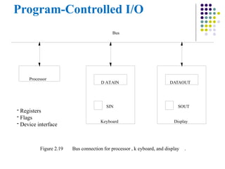
Program-Controlled I/O
- Registers
-Flags
- Device interface
D ATAIN DATAOUT
SIN
Keyboard
SOUT
Display
Bus
Figure 2.19 Bus connection for processor , k eyboard, and display .
Processor
60.
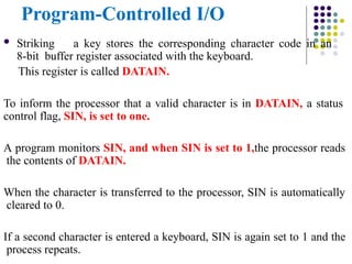
Program-Controlled I/O
Strikinga key stores the corresponding character code in an
8-bit buffer register associated with the keyboard.
This register is called DATAIN.
To inform the processor that a valid character is in DATAIN, a status
control flag, SIN, is set to one.
A program monitors SIN, and when SIN is set to 1,the processor reads
the contents of DATAIN.
When the character is transferred to the processor, SIN is automatically
cleared to 0.
If a second character is entered a keyboard, SIN is again set to 1 and the
process repeats.
61.
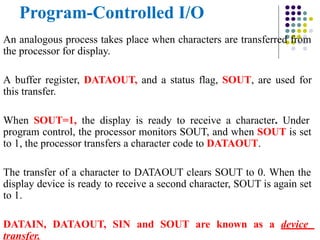
Program-Controlled I/O
An analogousprocess takes place when characters are transferred from
the processor for display.
A buffer register, DATAOUT, and a status flag, SOUT, are used for
this transfer.
When SOUT=1, the display is ready to receive a character. Under
program control, the processor monitors SOUT, and when SOUT is set
to 1, the processor transfers a character code to DATAOUT.
The transfer of a character to DATAOUT clears SOUT to 0. When the
display device is ready to receive a second character, SOUT is again set
to 1.
DATAIN, DATAOUT, SIN and SOUT are known as a device
transfer.
62.
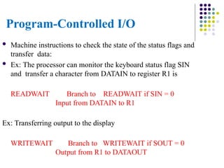
Program-Controlled I/O
Machineinstructions to check the state of the status flags and
transfer data:
Ex: The processor can monitor the keyboard status flag SIN
and transfer a character from DATAIN to register R1 is
READWAIT Branch to READWAIT if SIN = 0
Input from DATAIN to R1
Ex: Transferring output to the display
WRITEWAIT Branch to WRITEWAIT if SOUT = 0
Output from R1 to DATAOUT
63.
Memory-Mapped I/O
Manycomputers use the arrangement called Memory-Mapped I/O in
which some memory address values are used to refer to peripheral
device buffer registers, such as DATAIN and DATAOUT.
No special instructions are needed to access the contents of
these registers.
READWAIT Testbit #3, INSTATUS
Branch=0
READWAIT MoveByte
DATAIN, R1
64.
Model Questions
1. Whatis performance measurement? explain the overall SPEC rating
for the computer in a program suite.
2. Mention four types of operations to be performed by instructions in
a computer. Explain with basic types of instruction formats to carry
out C = [A]+[B].
3. Define an addressing mode. Explain the different addressing modes
with example.
4. Explain the connection between processor and memory.
5. A program contain 1000 instructions. Out of that 25% instructions
require 4 clock cycles, 40% instructions require 5 cock cycles and
remaining requires 3 clock cycles for execution. Find the total time
required to execute the program running in a 1 GHz machine.
65.
Model Questions
6. Drawthe arrangement of a single bus structure and brief
about memory mapped IO.
7. With a neat block diagram, describe the IO operations.
8. Derive the basic performance equation.
9. Registers R1 and R2 of a computer contain the decimal values 1200
and 4600. what is EA of the memory opened in each of the
following instructions?
I) Load 20(R1),R5 II) Move #3000,R5 III) Store R5,
30(R1,R2) IV) Add -(R2) R5 V) Subtract (R1)+ , R5


![Register Transfer Notation
Identify a location by a symbolic name standing for its
hardware binary address
Ex: For address of memory location: LOC,PLACE,A,VAR2
For processor registers: R0,R1
For I/O registers: DATAIN, OUTSTATUS
Contents of a location are denoted by placing square brackets around
the name of the location
Ex: R1←[LOC] ----The contents of memory location LOC are
transferred into processor register R1
R3 ←[R1]+[R2]
This type of notation is known as Register Transfer Notation (RTN)](https://image.slidesharecdn.com/module-3-co-instructionsandprograms-250525092253-46c781c8/85/MODULE-3-CO-Instructions-and-Programs-pptx-20-320.jpg)
![Assembly Language Notation
To represent machine instructions and programs.
Ex: Move LOC, R1 ;R1←[LOC] Add R1,
R2, R3 ;R3 ←[R1]+[R2]](https://image.slidesharecdn.com/module-3-co-instructionsandprograms-250525092253-46c781c8/85/MODULE-3-CO-Instructions-and-Programs-pptx-21-320.jpg)
![Basic Instruction Types
Three-Address Instructions
ADD R1, R2, R3 ;R3 ← R1 + R2
Two-Address Instructions
ADD R1, R2 ;R2 ← R1 + R2
One-Address Instructions
ADD A ;AC ← AC + M[A]
Opcode Operand(s) or Address(es)](https://image.slidesharecdn.com/module-3-co-instructionsandprograms-250525092253-46c781c8/85/MODULE-3-CO-Instructions-and-Programs-pptx-22-320.jpg)
![Basic Instruction Types
Example: Evaluate
C=A+B
Three-Address ADD A, B, C
Two-Address ADD A,B
MOVE B,C
[OR] MOVE A,R1
ADD B,R1
MOVE R1,C
One-Address LOAD A
ADD B
STORE C](https://image.slidesharecdn.com/module-3-co-instructionsandprograms-250525092253-46c781c8/85/MODULE-3-CO-Instructions-and-Programs-pptx-23-320.jpg)
![Basic Instruction Types
Example: Evaluate E=(A+B) (C+D)
Three-Address
ADD A, B, R1
ADD C, D, R2
MUL R1, R2, E
; R1 ← M[A] + M[B]
; R2 ← M[C] + M[D]
; M[E] ← R1 R2](https://image.slidesharecdn.com/module-3-co-instructionsandprograms-250525092253-46c781c8/85/MODULE-3-CO-Instructions-and-Programs-pptx-24-320.jpg)
![Basic Instruction Types
Example: Evaluate E=(A+B) (C+D)
Two-Address
MOV A, R1 ; R1 ← M[A]
ADD B, R1 ; R1 ← R1 + M[B]
MOV C, R2 ; R2 ← M[C]
ADD D, R2 ; R2 ← R2 + M[D]
MUL R1,
R2
; R2 ← R1 R2
MOV R2,E ; M[E] ← R2](https://image.slidesharecdn.com/module-3-co-instructionsandprograms-250525092253-46c781c8/85/MODULE-3-CO-Instructions-and-Programs-pptx-25-320.jpg)
![Basic Instruction Types
Example: Evaluate E=(A+B) (C+D)
One-Address
LOAD
A
; AC ← M[A]
; AC ← AC + M[B]
; R1 ← AC
; AC ← M[C]
; AC ← AC + M[D]
; AC ← AC R1
; M[E] ← AC
ADD B
STORE R1
LOAD C
ADD D
MUL R1
STORE E](https://image.slidesharecdn.com/module-3-co-instructionsandprograms-250525092253-46c781c8/85/MODULE-3-CO-Instructions-and-Programs-pptx-26-320.jpg)
![Addressing Modes
Ex: Move 200immediate ,R0 [or] Move
#200,R0 Place the value 200 in register R0.
The Immediate mode is only used to specify the value of a source
operand.
Constant values are used in HLL programs.
Ex: A=B+6
Assuming that A & B have been declared as variables and may be
accessed using the absolute mode. This statement may be compiled
as follows.
Move B,R1
Add #6,R1
Move R1,A](https://image.slidesharecdn.com/module-3-co-instructionsandprograms-250525092253-46c781c8/85/MODULE-3-CO-Instructions-and-Programs-pptx-39-320.jpg)
![Addressing Modes
Indexing and Arrays
5. Index Mode : The EA of the operand
is generated by adding a constant value to the
contents of a register (index register).
The register may be either a special or
may be any one of general purpose registers in a
processor.
Ex: X(Ri) ; where X=constant value contained in the instruction.
Ri=name of the register involved.
The EA of the operand is given by EA = [Ri] + X
The contents of the index register is not changed in the process of
generating the effective address.](https://image.slidesharecdn.com/module-3-co-instructionsandprograms-250525092253-46c781c8/85/MODULE-3-CO-Instructions-and-Programs-pptx-42-320.jpg)
![Addressing Modes
Indexing and Arrays
6. Base with Index : The effective address is the sum of the contents
of registers Ri and Rj. The second register is usually called as base
register.
Ex: (Ri,Rj) ;EA = [Ri] + [Rj]
7. Base with index and Offset : The effective address is the sum of
the constant X and the contents of registers Ri and Rj.
Ex: X(Ri,Rj) ;EA = [Ri] + [Rj] + X](https://image.slidesharecdn.com/module-3-co-instructionsandprograms-250525092253-46c781c8/85/MODULE-3-CO-Instructions-and-Programs-pptx-46-320.jpg)
![Addressing Modes
Relative Addressing
8. Relative mode: The EA is determined by the index mode
using
the PC in place of the general purpose register Ri.
Ex: X(PC) ;EA= [PC] + X
This mode can be used to access data operands.
Commonly used to specify target address in branch instruction.
Branch>0 LOOP
This location is computed by specifying it as an offset from the
current value of PC.
Branch target may be either before or after the branch instruction,
the offset is given as a singed num.](https://image.slidesharecdn.com/module-3-co-instructionsandprograms-250525092253-46c781c8/85/MODULE-3-CO-Instructions-and-Programs-pptx-47-320.jpg)
![Model Questions
1. What is performance measurement? explain the overall SPEC rating
for the computer in a program suite.
2. Mention four types of operations to be performed by instructions in
a computer. Explain with basic types of instruction formats to carry
out C = [A]+[B].
3. Define an addressing mode. Explain the different addressing modes
with example.
4. Explain the connection between processor and memory.
5. A program contain 1000 instructions. Out of that 25% instructions
require 4 clock cycles, 40% instructions require 5 cock cycles and
remaining requires 3 clock cycles for execution. Find the total time
required to execute the program running in a 1 GHz machine.](https://image.slidesharecdn.com/module-3-co-instructionsandprograms-250525092253-46c781c8/85/MODULE-3-CO-Instructions-and-Programs-pptx-64-320.jpg)