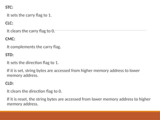
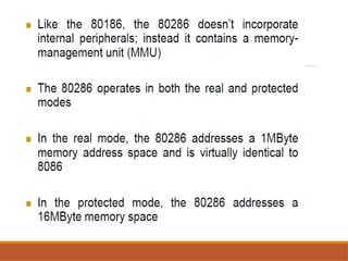
The document provides an overview of the 8086 microprocessor's instruction sets, describing the definition and structure of instructions and their associated fields. It categorizes instructions into main types, including data transfer, arithmetic, bit manipulation, and more, detailing specific instructions within these categories along with their syntax and examples. The document serves as a comprehensive guide for understanding how to utilize the 8086 instruction set effectively.
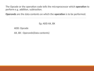
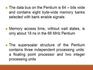
![Data transfer Instructions
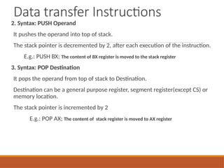
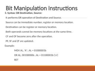
1. Syntax: MOV Destination, Source:
Source operand can be register, memory location or immediate operand.
Destination can be register or memory operand.
Both Source and Destination cannot be memory location at the same time.
Example:
MOV CX, 037A H; The data 037A H is moved to CX Register
MOV AL, BL; The data in BL register is moved to AL Register
MOV BX, [0301 H]; The data in the memory location [0301 H] is moved to BX
Register](https://image.slidesharecdn.com/instructionsetsof8086-240926081923-91b9afe3/85/instructionsetsofjdtufgmictfgfjh8086-pptx-8-320.jpg)
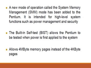
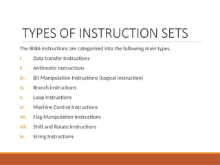
![Data transfer Instructions
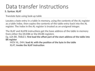
4. Syntax: XCHG Destination, Source:
This instruction exchange the contents of the specified source and destination
operands
It cannot exchange two memory locations directly.
E.g.
XCHG DX, AX; The content in AX and DX register is exchanged.
If AX contains 0234 H and DX contains 45AD H after execution AX contains 45AD H and
DX contains 0234 H
XCHG [5000H], AX;](https://image.slidesharecdn.com/instructionsetsof8086-240926081923-91b9afe3/85/instructionsetsofjdtufgmictfgfjh8086-pptx-10-320.jpg)
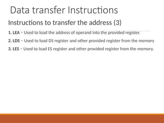
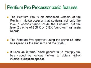
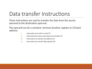
![Data transfer Instructions
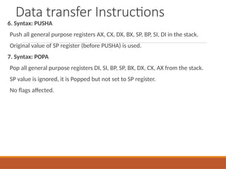
1. Syntax: LEA Register, Source
Load effective address
It loads a 16-bit register with the offset address of the data specified by the
Source.
E.g.: MOV BX, 35h
MOV DI, 12h
LEA SI, [BX+DI] ; SI = 35h + 12h = 47h](https://image.slidesharecdn.com/instructionsetsof8086-240926081923-91b9afe3/85/instructionsetsofjdtufgmictfgfjh8086-pptx-15-320.jpg)
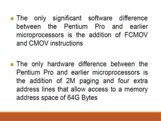
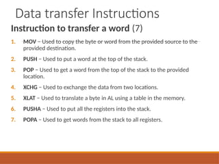
![Data transfer Instructions
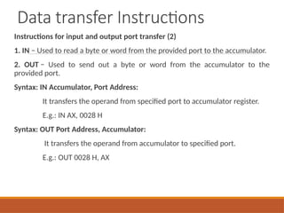
2. Syntax: LDS Destination, Source:
It loads 32-bit pointer from memory source to destination register and DS.
The offset is placed in the destination register and the segment is placed in DS.
To use this instruction the word at the lower memory address must contain
the offset and the word at the higher address must contain the segment.
E.g.: LDS BX, [0301 H]](https://image.slidesharecdn.com/instructionsetsof8086-240926081923-91b9afe3/85/instructionsetsofjdtufgmictfgfjh8086-pptx-16-320.jpg)
![Data transfer Instructions
3. Syntax: LES Destination, Source:
It loads 32-bit pointer from memory source to destination register and ES.
The offset is placed in the destination register and the segment is placed in ES.
This instruction is very similar to LDS except that it initializes ES instead of DS.
E.g.: LES BX, [0301 H]](https://image.slidesharecdn.com/instructionsetsof8086-240926081923-91b9afe3/85/instructionsetsofjdtufgmictfgfjh8086-pptx-17-320.jpg)
![Arithmetic Instructions
These instructions are used to perform arithmetic operations like addition,
subtraction, multiplication, division, etc.
1. Syntax: ADD Destination, Source
It adds a byte to byte or a word to word.
It affects AF, CF, OF, PF, SF, ZF flags.
E.g.:
ADD AL, 74H
ADD DX, AX
ADD AX, [BX]](https://image.slidesharecdn.com/instructionsetsof8086-240926081923-91b9afe3/85/instructionsetsofjdtufgmictfgfjh8086-pptx-19-320.jpg)
![Arithmetic Instructions
2. Syntax: ADC Destination, Source
It adds the two operands with CF.
It affects AF, CF, OF, PF, SF, ZF flags.
E.g.:
ADC AL, 74H;
ADC DX, AX;
ADC AX, [BX];](https://image.slidesharecdn.com/instructionsetsof8086-240926081923-91b9afe3/85/instructionsetsofjdtufgmictfgfjh8086-pptx-20-320.jpg)
![Arithmetic Instructions
3. Syntax: SUB Destination, Source:
It subtracts a byte from byte or a word from word.
It affects AF, CF, OF, PF, SF, ZF flags.
For subtraction, CF acts as borrow flag.
E.g.:
SUB AL, 74H;
SUB DX, AX;
SUB AX, [BX];](https://image.slidesharecdn.com/instructionsetsof8086-240926081923-91b9afe3/85/instructionsetsofjdtufgmictfgfjh8086-pptx-21-320.jpg)
![Arithmetic Instructions
4. Syntax: SBB Destination, Source:
It subtracts the two operands and also the borrow from the result.
It affects AF, CF, OF, PF, SF, ZF flags.
E.g.:
SBB AL, 74H;
SBB DX, AX;
SBB AX, [BX];](https://image.slidesharecdn.com/instructionsetsof8086-240926081923-91b9afe3/85/instructionsetsofjdtufgmictfgfjh8086-pptx-22-320.jpg)

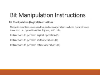
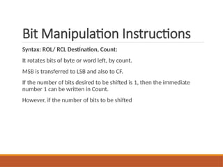
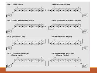
![Bit Manipulation Instructions
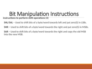
Instructions to perform Rotate operations (4)
1. ROL − Used to rotate bits of byte/word towards the left, i.e. MSB to LSB and
to Carry Flag [CF].
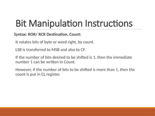
2. ROR − Used to rotate bits of byte/word towards the right, i.e. LSB to MSB
and to Carry Flag [CF].
3. RCR − Used to rotate bits of byte/word towards the right, i.e. LSB to CF and
CF to MSB.
4. RCL − Used to rotate bits of byte/word towards the left, i.e. MSB to CF and CF
to LSB.](https://image.slidesharecdn.com/instructionsetsof8086-240926081923-91b9afe3/85/instructionsetsofjdtufgmictfgfjh8086-pptx-44-320.jpg)