This document provides important safety information and references for Logix5000 controllers. It describes required safety practices for installation, configuration, operation and maintenance. The document notes that all activities must be carried out by suitably trained personnel according to applicable codes and standards. Rockwell Automation takes no responsibility for improper use or indirect/consequential damages resulting from use of this equipment.


![Rockwell Automation Publication 1756-RM003P-EN-P - December 2014 75
FactoryTalk Alarmsand Events Logix-based Instructions (ALMD, ALMA) Chapter 1
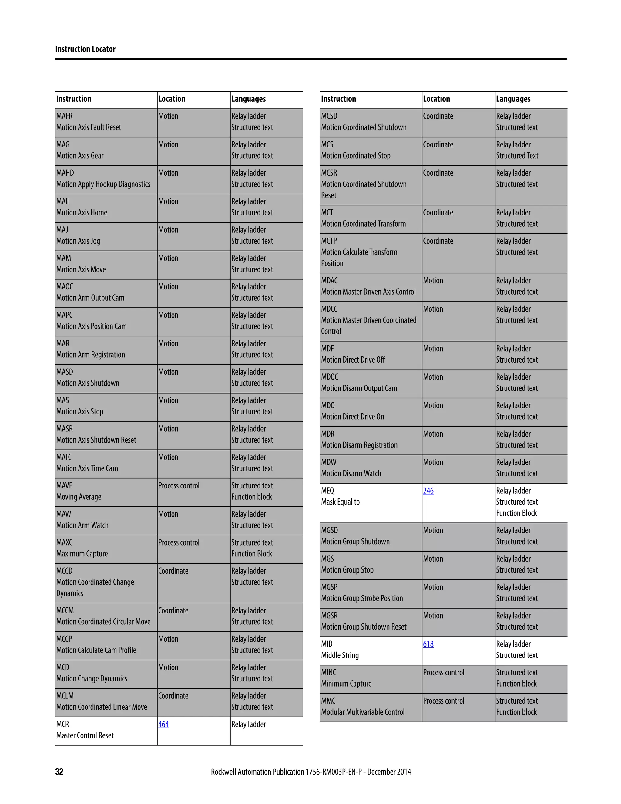
Message String Variables
The code varies depending on the type of tag you select, how many digits or
characters are in a tag value, and whether you want to left fill the empty bits with
spaces or zeroes. See the following example.
All of this variable information is included with the alarm data, viewable by the
operator, and entered in the history log, regardless of whether you embed the
information in the message text.
Variable Embeds in the message string Default code added to message string
Alarm name Thenameofthealarm,whichconsistsofthecontrollername,program
name, and tag name. For example,
[Zone1Controller]Program:Main.MyAlarmTagName.
/*S:0 %AlarmName*/
Condition name The condition that triggers the alarm:
• Digital alarm displays the trip.
• Analog alarm displays HiHi, Hi, Lo, LoLo, ROC_POS, or ROC_NEG.
/*S:0 %ConditionName*/
Input value The input value to the alarm:
• Digital alarm displays 0 or 1.
• Analog alarm displays the value of the input variable being
monitored by the alarm.
/*N:5 %InputValue NOFILL DP:0*/
Limit value The threshold of the alarm:
• Digital alarm displays 0 or 1.
• Analog alarm displays the actual configured range check for the
analog alarm condition.
/*N:5 %LimitValue NOFILL DP:0*/
Severity The configured severity of the alarm condition. /*N:5 %Severity NOFILL DP:0*/
Values of associated tags The value of a tag configured to be included with the alarm event. /*N:5 %Tag1 NOFILL DP:0*/
Tag Code
BOOL value /*N:1 %Tag1 NOFILL DP:0*/
DINT value, 9 digits, space left fill /*N:9 %Tag2 SPACEFILL DP:0*/
REALinputvalue,9digits(includesdecimal),3 digitsafterdecimal,zeroleft
fill
/*N:9 %InputValue NOFILL DP:3*/
REAL value, 8 digits (includes decimal), 4 digits after decimal, zero left fill /*N:8 %Tag3 ZEROFILL DP:4*/
String value, no fixed width /*S:0 %Tag4*/
String value, 26 characters, fixed width /*S:26 %Tag4*/](https://image.slidesharecdn.com/1756-rm003-en-p-150617024022-lva1-app6892/75/1756-rm003-en-p-75-2048.jpg)


![88 Rockwell Automation Publication 1756-RM003P-EN-P - December 2014
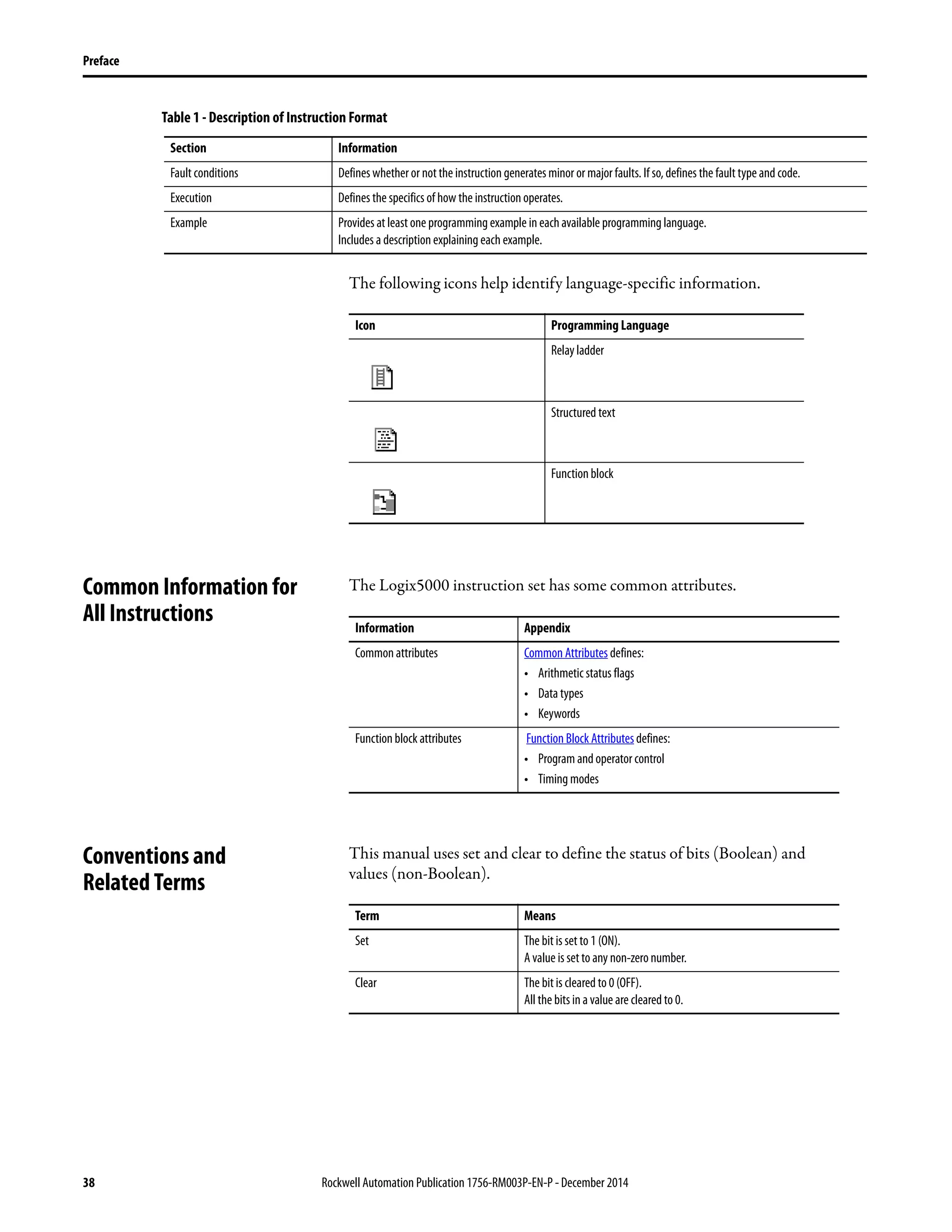
Chapter 2 Bit Instructions (XIC, XIO, OTE, OTL, OTU, ONS, OSR, OSF, OSRI, OSFI)
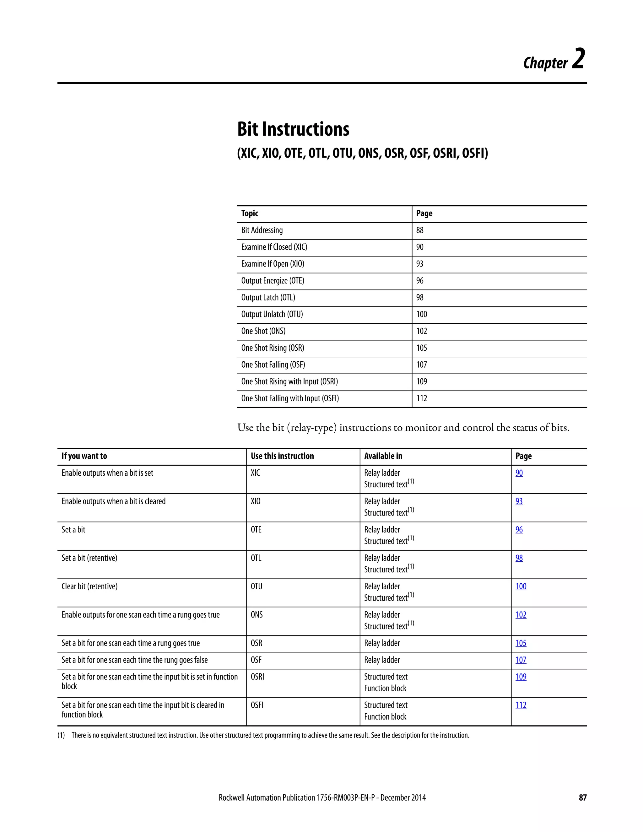
Bit Addressing Bits in a Logix controller exist in one of several forms:
• BOOL tag
• BOOL array
• Bits within an integer (SINT, INT, or DINT) tag
• Bits within an integer array
Any of the above constructs may also exist as members of a structure, whether it’s
a system defined data type (SDT) or user-defined data type (UDT).
Bits defined as BOOLs are referenced simply by name. For example, XIC
myBool.
Bits within BOOL arrays are referenced by a subscript appended to the array
name. Subscripts can be a literal value (for example, XIC boolArray[31]), a tag
(for example, XIC boolArray[index]), or an expression (for example, XIC
boolArray[index+1]).
Bits within an integer tag or integer array may be addressed similarly. This is what
Logix often refers to as bit addressing mode for integers. IEC 61131-3 might
refer to it as ‘partial access of ANY_BIT variables’. Bit addressing for integers is
programmed by adding a dot (or period) to the integer indicating subelement
processing followed by a subscript (for example, myInteger[3].11 addresses bit
11, subelement [3]of the myInteger array). There is a shorthand form for literal
subscripts in this case, which is simply a dot followed by the literal value (for
example, myInteger.3, meaning bit 3 of myInteger). Similar to subscripts for
BOOL arrays above, one can specify a tag or expression for the subscript.
Integer arrays are dealt with similarly except that you must specify a member of
the array from which indexing begins. For example, XIC
myIntArray[4].[index+1] says to start at the 5th element of myIntArray and
access bit ‘index+1.’ Bounds checking is performed on all subscripts to make sure
the reference does not go beyond the boundary of the data object specified.
Literals are checked for conformance during verification.](https://image.slidesharecdn.com/1756-rm003-en-p-150617024022-lva1-app6892/75/1756-rm003-en-p-88-2048.jpg)
![Rockwell Automation Publication 1756-RM003P-EN-P - December 2014 89
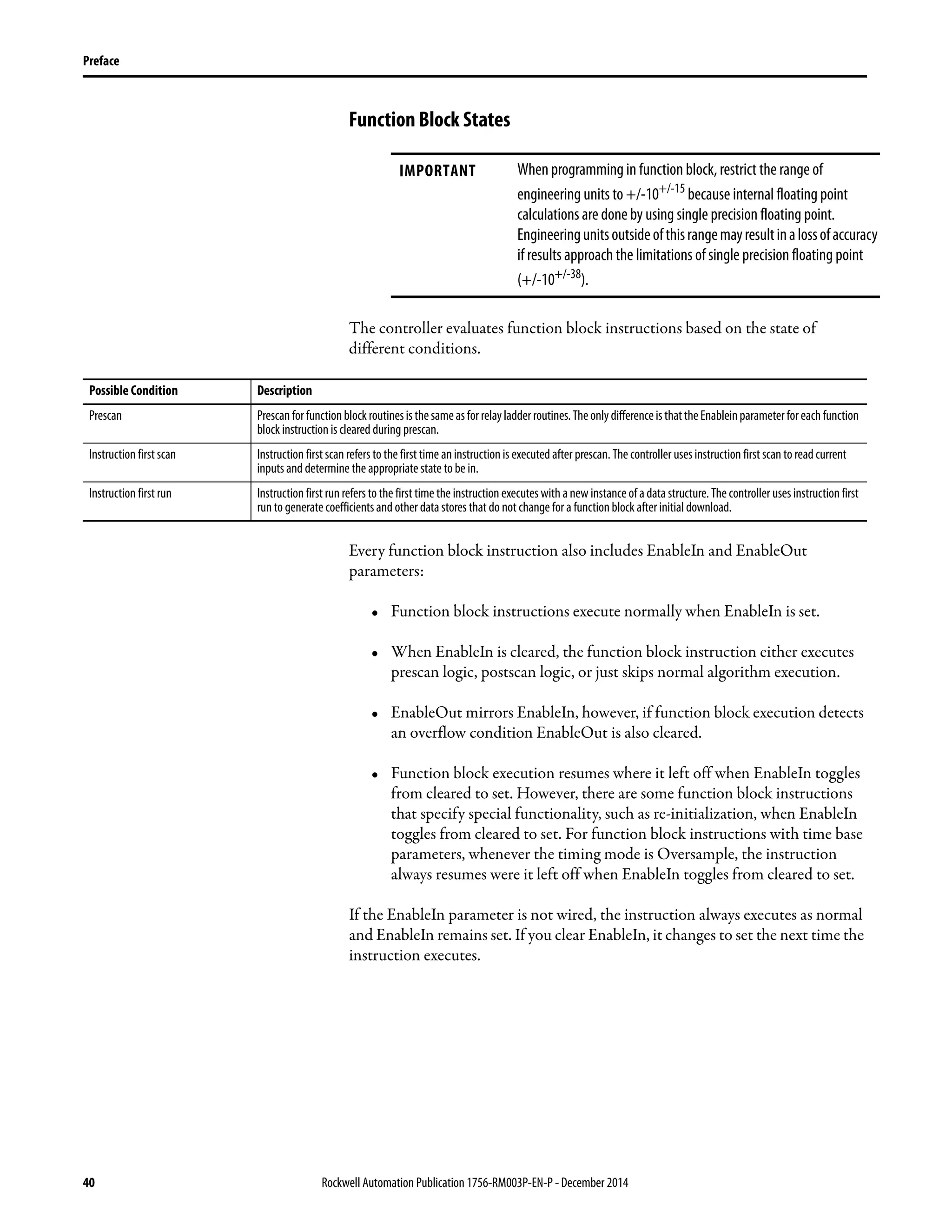
Bit Instructions (XIC, XIO, OTE, OTL, OTU, ONS, OSR, OSF, OSRI, OSFI) Chapter 2
Example: Indirect Serial Bit Reference in a DINT array
Tag
MyBits : DINT[10]
BitRef : DINT
EndTag
MOV(34,BitRef)
XIC(MyBits[(BitRef AND NOT 31)/32].[BitRef AND 31])
Explanation
(BitRef AND NOT 31)/32=Calculates the element in the DINT
.[BitRef AND 31]=Calculates the bit within the element
If the tag MyBits is defined as an INT or SINT, the mask value would be 15 or 7,
respectively. Both the Diagnostic Detect (DDT) and File Bit Compare (FBC)
instructions provide a bit number as a result of their operation. These
instructions are limited to DINT arrays, and so the indirect addressing example
can be used to programmatically locate the bit number returned from these
instructions.](https://image.slidesharecdn.com/1756-rm003-en-p-150617024022-lva1-app6892/75/1756-rm003-en-p-89-2048.jpg)


![96 Rockwell Automation Publication 1756-RM003P-EN-P - December 2014
Chapter 2 Bit Instructions (XIC, XIO, OTE, OTL, OTU, ONS, OSR, OSF, OSRI, OSFI)
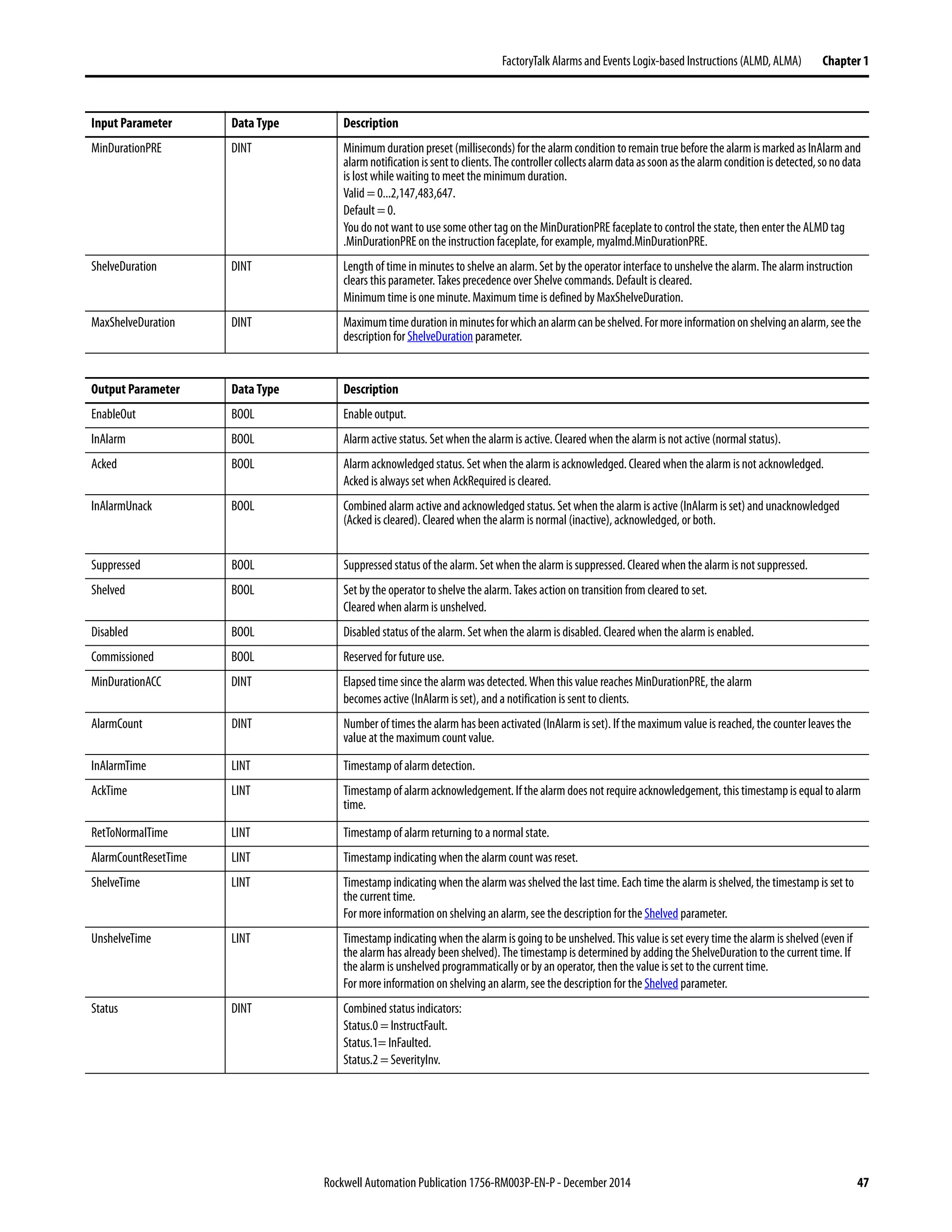
Output Energize (OTE) The OTE instruction sets or clears the data bit.
Operands:
Relay Ladder
Structured Text
Structured text does not have an OTE instruction, but you can achieve the same
results by using a non-retentive assignment.
data_bit [:=] BOOL_expression;
See Function Block Attributes for information on the syntax of assignments and
expressions within structured text.
Description: When the OTE instruction is enabled, the controller sets the data bit. When the
OTE instruction is disabled, the controller clears the data bit.
Arithmetic Status Flags: Not affected
Fault Conditions: None
Execution:
Operand Type Format Description
Data bit BOOL Tag Bit to be set or cleared
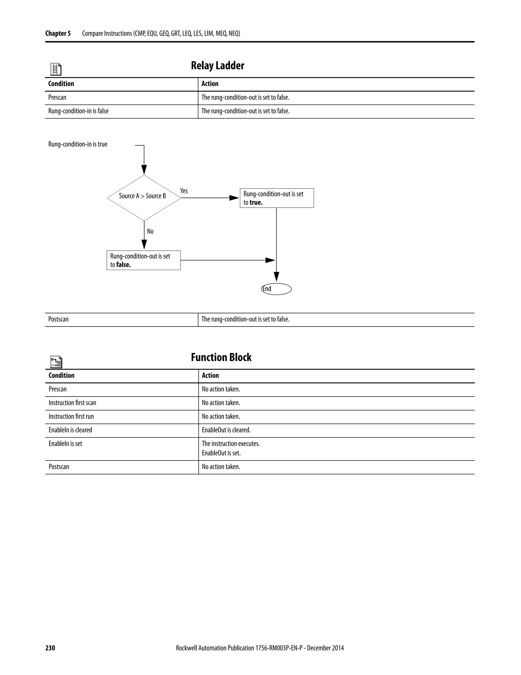
Condition Relay Ladder Action
Prescan The data bit is cleared.
The rung-condition-out is set to false.
Rung-condition-in is false The data bit is cleared.
The rung-condition-out is set to false.
Rung-condition-in is true The data bit is set.
The rung-condition-out is set to true.
Postscan The data bit is cleared.
The rung-condition-out is set to false.](https://image.slidesharecdn.com/1756-rm003-en-p-150617024022-lva1-app6892/75/1756-rm003-en-p-96-2048.jpg)
![Rockwell Automation Publication 1756-RM003P-EN-P - December 2014 97
Bit Instructions (XIC, XIO, OTE, OTL, OTU, ONS, OSR, OSF, OSRI, OSFI) Chapter 2
Example: When switch is set, the OTE instruction sets (turns on) light_1. When switch is
cleared, the OTE instruction clears (turns off) light_1.
Relay Ladder
Structured Text
light_1 [:=] switch;](https://image.slidesharecdn.com/1756-rm003-en-p-150617024022-lva1-app6892/75/1756-rm003-en-p-97-2048.jpg)


![156 Rockwell Automation Publication 1756-RM003P-EN-P - December 2014
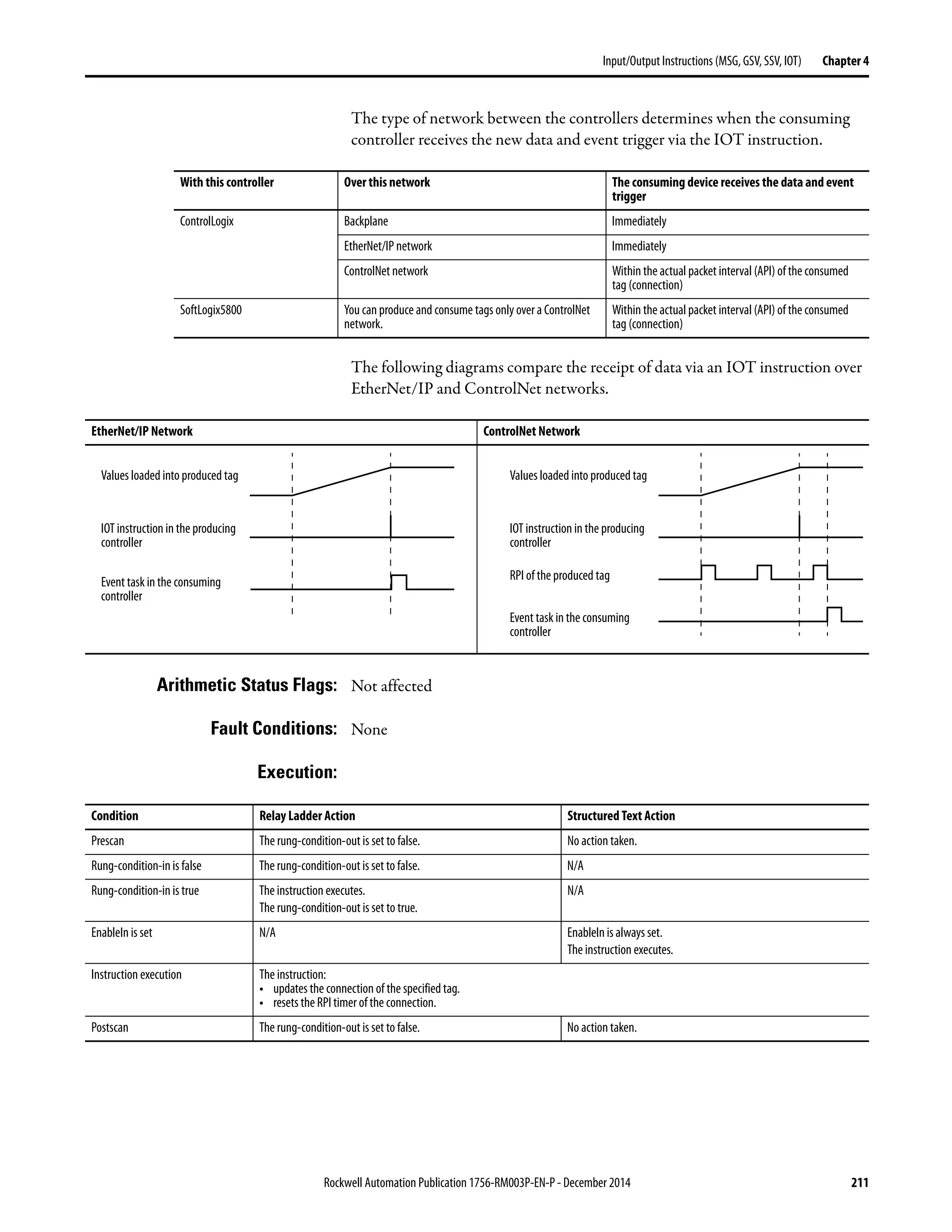
Chapter 4 Input/Output Instructions (MSG, GSV, SSV, IOT)
.LocalIndex DINT Ifyouuseanasterisk[*]todesignatetheelementnumber ofthelocalarray,theLocalIndexprovidestheelementnumber.Tochange
the element number, set this member to the required value.
If the message Then the local array is
Reads data Destination element
Writes data Sourceelement
.Channel SINT To send the message out a different channel of the 1756-DHRIO module, set this member to the required value. Use either the ASCII
character A or B.
.Rack SINT To change the rack number fora block transfer message, set this member to the required rack number (octal).
.Group SINT To change the group number for a block transfer message, set this member to the required group number (octal).
.Slot SINT To change the slot number for a block transfer message, set this member to the required slot number.
Ifthemessagegoesover
this network
Then specify the slot number
Universal remote I/O Octal
ControlNet Decimal (0…15)
.Path STRING To send the message to a different controller, set this member to the new path.
• Enter the path as hexadecimal values.
• Omit commas [,]
For example, for a path of 1, 0, 2, 42, 1, 3, enter $01$00$02$2A$01$03.
To browse to a device and automatically create a portion or all of the new string, right-click a string tag and choose ‘Goto Message
PathEditor’.
.RemoteIndex DINT If you use an asterisk [*] to designate the element number of the remote array, the RemoteIndex provides the element number. To
change the element number, set this member to the required value.
If the message Then the remote array is
Reads data Source element
Writes data Destination element
.RemoteElement STRING To specify a different tag or address in the controller to which the message is sent, set this member to the required value. Enter the
tag or address as ASCII characters.
If the message Then the remote array is
Reads data Source element
Writes data Destination element
.UnconnnectedTimeout DINT Time out for an unconnected messageor for making a connection. The default value is 30 seconds.
If the message is Then
Unconnected The ER bit turns on if the controller doesn’t get a response within the UnconnectedTimeout time.
Connected The ER bit turns on if the controller doesn’t get a response for making the connection within the
UnconnectedTimeout time.
.ConnectionRate DINT Timeoutforaconnectedmessageonceithasaconnection.Thistimeoutisfortheresponsefromtheotherdeviceaboutthesending
of the data.
• This time out applies only after the connection is made.
• The time out = ConnectionRatex TimeoutMultiplier.
• The default ConnectionRate is 7.5 seconds.
• The default TimeoutMultiplier is 0 (which is a multiplication factor of 4).
• The default time out for connected messages is 30 seconds (7.5 seconds x 4 = 30 seconds).
• To change the time out, change the ConnectionRate and leave the TimeoutMultiplier at the default value.
.TimeoutMultiplier SINT
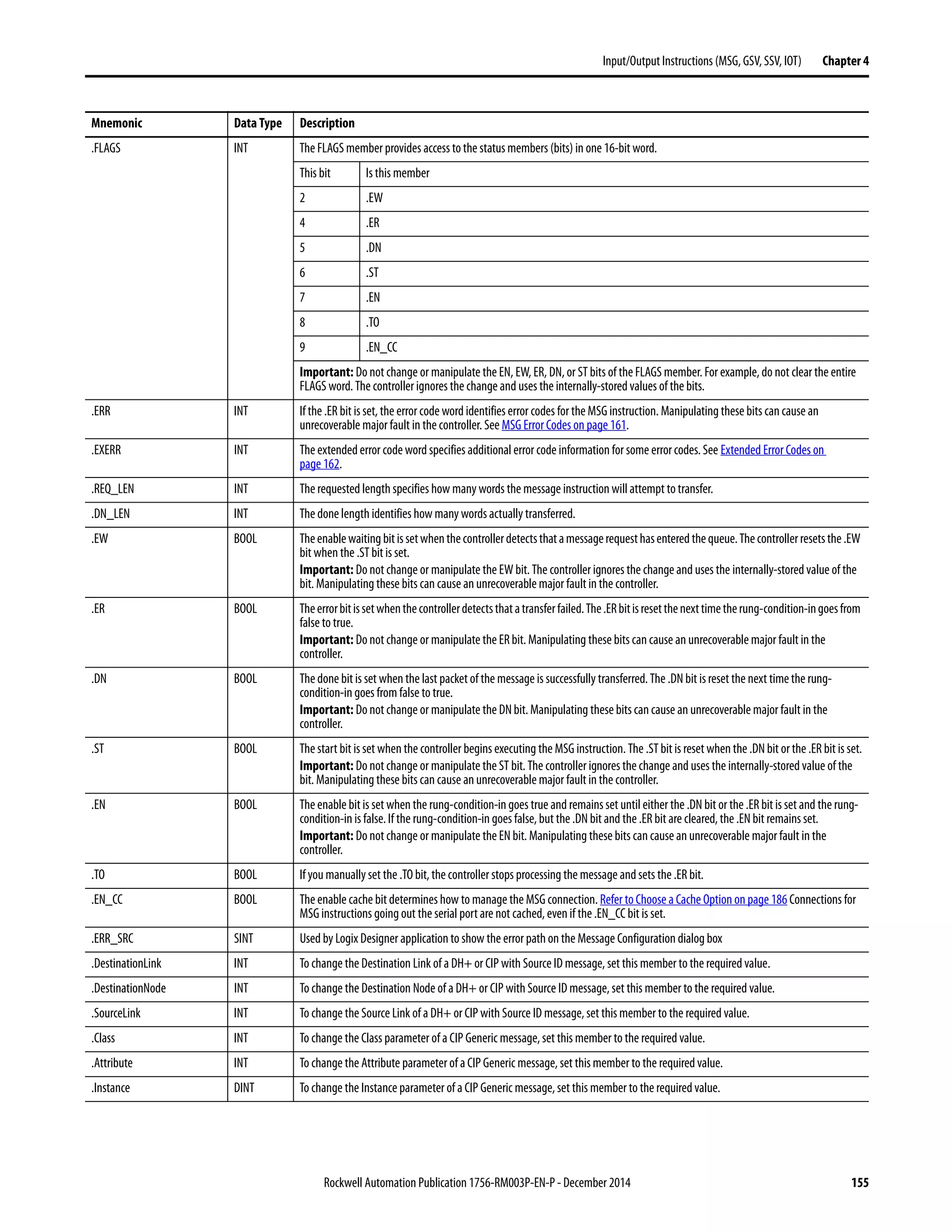
Mnemonic Data Type Description](https://image.slidesharecdn.com/1756-rm003-en-p-150617024022-lva1-app6892/75/1756-rm003-en-p-156-2048.jpg)


![170 Rockwell Automation Publication 1756-RM003P-EN-P - December 2014
Chapter 4 Input/Output Instructions (MSG, GSV, SSV, IOT)
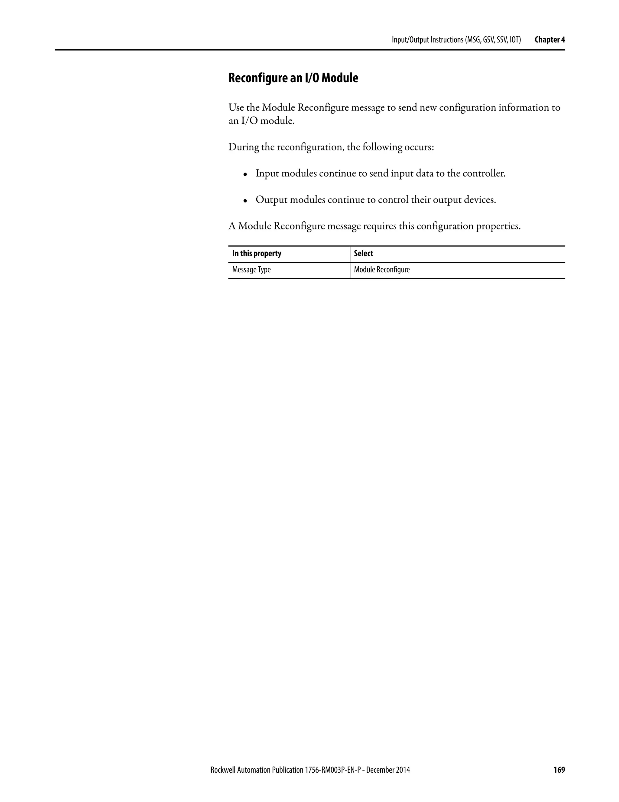
Example: Follow these steps to reconfigure an I/O module.
1. Set the required member of the configuration tag of the module to the new
value.
2. Send a Module Reconfigure message to the module.
When reconfigure[5] is set, set the high alarm to 60 for the local module in slot 4.
The Module Reconfigure message then sends the new alarm value to the module.
The one shot instruction prevents the rung from sending multiple messages to
the module while the reconfigure[5] is on.
Relay Ladder
Structured Text
IF reconfigure[5] AND NOT reconfigure[6]THEN
Local:4:C.Ch0Config.HAlarmLimit := 60;
IF NOT change_Halarm.EN THEN
MSG(change_Halarm);
END_IF;
END_IF;
reconfigure[6] := reconfigure[5];
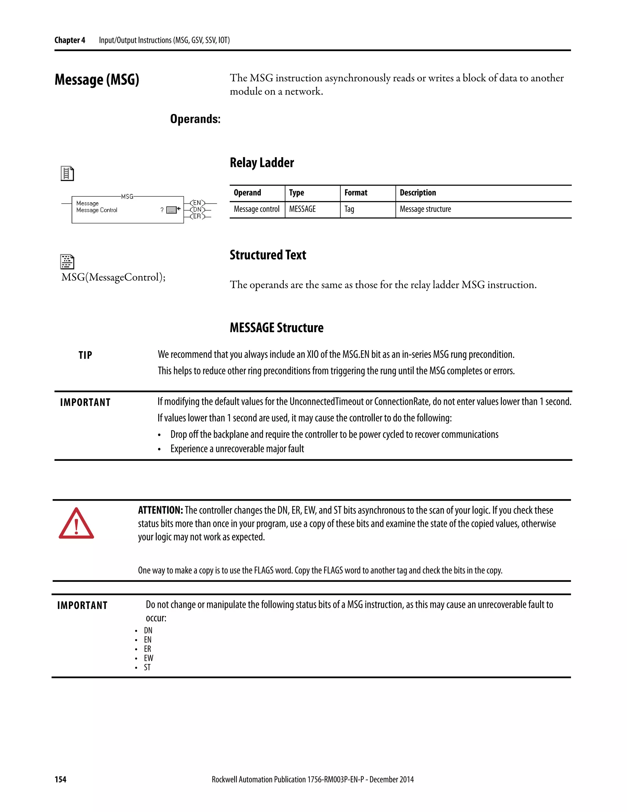
TIP We recommend that you always include an XIO of the MSG.EN bit as an in-series MSG
rung precondition.](https://image.slidesharecdn.com/1756-rm003-en-p-150617024022-lva1-app6892/75/1756-rm003-en-p-170-2048.jpg)
![Rockwell Automation Publication 1756-RM003P-EN-P - December 2014 171
Input/Output Instructions (MSG, GSV, SSV, IOT) Chapter 4
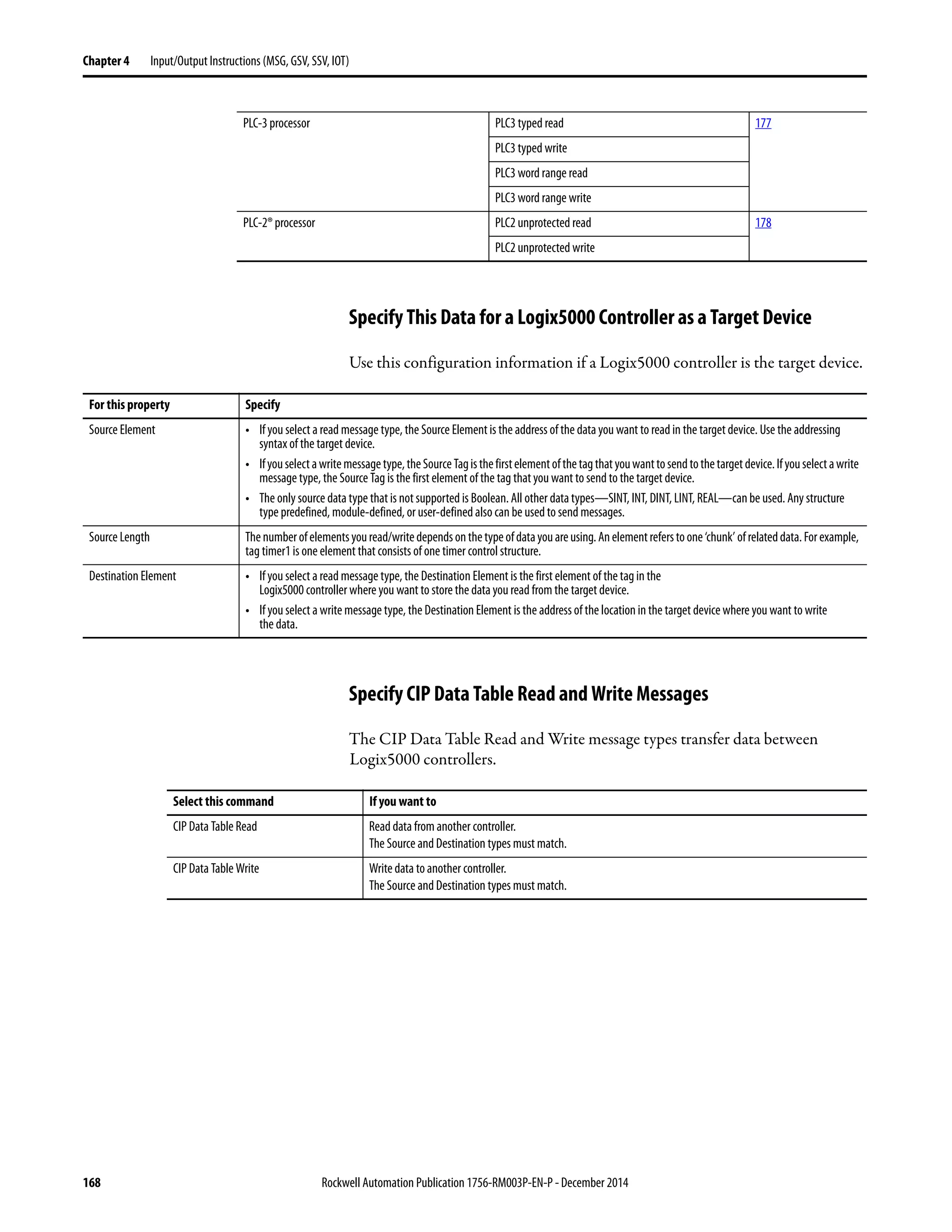
Specify CIP Generic Messages
IMPORTANT ControlLogix modules have services that can be invoked by using a MSG
instruction and choosing the CIP Generic message type.
If you want to In this property Type or select
Perform a pulse test on a digital output module Message Type CIP Generic
Service Type Pulse Test
Source tag_name of type INT [5]
This array contains Description
tag_name[0] Bit mask of points to test (test only one point at a time)
tag_name[1] Reserved, leave 0
tag_name[2] Pulse width (hundreds of μs, usually 20)
tag_name[3] Zero cross delay for ControlLogix I/O (hundreds of μs,
usually 40)
tag_name[4] Verify delay
Destination Blank
Get audit value Message Type CIP Generic
Service Type Audit Value Get
Source Element Cannot change this field, blank
Source Length Cannot change this field, set to 0 bytes
Destination Element This array contains Description
tag_name of type DINT[2] or
LINT
This tag contains the Audit Value for the controller.
IMPORTANT: We recommend using the DINT[2] data type
to avoid limitations when working with LINT data types in
Allen-Bradley® controllers.
Get controller events monitored for changes
See Table 4
Message Type CIP Generic
Service Type Changes to Detect Get
Source Element Cannot change this field, blank
Source Length Cannot change this field, set to 0 bytes
Destination Element This array contains Description
tag_name of type DINT[2] or
LINT
Thistagrepresentsabitmaskofthechangesmonitoredfor
the controller.
IMPORTANT: We recommend using the DINT[2] data type
to avoid limitations when working with LINT data types in
Allen-Bradley controllers.](https://image.slidesharecdn.com/1756-rm003-en-p-150617024022-lva1-app6892/75/1756-rm003-en-p-171-2048.jpg)
![172 Rockwell Automation Publication 1756-RM003P-EN-P - December 2014
Chapter 4 Input/Output Instructions (MSG, GSV, SSV, IOT)
Set controller events monitored for changes
See Table 4
Message Type CIP Generic
Service Type Changes to Detect Set
Source Element This array contains Description
tag_name of type DINT[2] or
LINT
Thistagrepresentsabitmaskofthechangesmonitoredfor
the controller.
IMPORTANT: We recommend using the DINT[2] data type
to avoid limitations when working with LINT data types in
Allen-Bradley controllers.
Source Length Cannot change this field, set to 8 bytes
Destination Element Cannotchange this field, blank
Reset electronic fuses on a digital output module Message Type CIP Generic
Service Type Reset Electronic Fuse
Source tag name of type DINT
This tag represents a bit mask of the points to reset fuses on.
Destination Leave blank
Reset latched diagnostics on a digital input module Message Type CIP Generic
Service Type Reset Latched Diagnostics (I)
Source tag_name of type DINT
This tag represents a bit mask of the points to reset diagnostics on.
Reset latched diagnostics on a digital output module Message Type CIP Generic
Service Type Reset Latched Diagnostics (O)
Source tag_name of type DINT
This tag represents a bit mask of the points to reset diagnostics on.
Unlatch the alarm of an analog input module Message Type CIP Generic
Service Type Select which alarm that you want to unlatch.
• Unlatch All Alarms (I)
• Unlatch Analog High Alarm (I)
• Unlatch Analog High High Alarm (I)
• Unlatch Analog Low Alarm (I)
• Unlatch Analog Low Low Alarm (I)
• Unlatch Rate Alarm (I)
Instance Channel of the alarm that you want to unlatch
Unlatch the alarm of an analog output module Message Type CIP Generic
Service Type Select which alarm that you want to unlatch.
• Unlatch All Alarms (O)
• Unlatch High Alarm (O)
• Unlatch Low Alarm (O)
• Unlatch Ramp Alarm (O)
Instance Channel of the alarm that you want to unlatch
If you want to In this property Type or select](https://image.slidesharecdn.com/1756-rm003-en-p-150617024022-lva1-app6892/75/1756-rm003-en-p-172-2048.jpg)
![Rockwell Automation Publication 1756-RM003P-EN-P - December 2014 173
Input/Output Instructions (MSG, GSV, SSV, IOT) Chapter 4
Table 4 - Get/Set Controller Events Monitored for Changes Bit Definitions
Tag Names Data Type Bit Definition
Get Controller Events Monitored for Changes
Set Controller Events Monitored for Changes
DINT[0] Bit
0
1
2
3
4
5
6
7
8
9
10
11
12
13
14
15
16
17
18
19
20
21
22
23
24
25
26
27
28
29
30
31
Meaning
Store to removable media through Logix Designer application
Online edits were accepted, tested, or assembled
Partial import online transaction completed
SFC Forces were enabled
SFC Forces were disabled
SFC Forces were removed
SFC Forces were modified
I/O Forces were enabled
I/O Forces were disabled
I/O Forces were removed
I/O Forces were changed
Firmwareupdate from unconnected source
Firmware update via removable media
Mode change via workstation
Mode change via mode switch
A major fault occurred
Major faults were cleared
Major faults were cleared via mode switch
Task properties were modified
Program properties were modified
Controller timeslice options were modified
Removable media was removed
Removable media was inserted
Safety signature created
Safety signature deleted
Safety lock
Safety unlock
Constant tag value changed
Constant tag multiple values changed
Constant tag attribute cleared
Tag set as constant
Custom log entry added
DINT[1] 32
33
34
35…63
Change that affects correlation
Helps protect signature in Run mode attribute set
Helps protect signature in Run mode attribute cleared
Unused](https://image.slidesharecdn.com/1756-rm003-en-p-150617024022-lva1-app6892/75/1756-rm003-en-p-173-2048.jpg)

![178 Rockwell Automation Publication 1756-RM003P-EN-P - December 2014
Chapter 4 Input/Output Instructions (MSG, GSV, SSV, IOT)
Specify PLC-2 Messages
The PLC-2 message types are designed for PLC-2 processors.
The message transfer uses 16-bit words, so make sure the Logix5000 tag
appropriately stores the transferred data (typically as an INTarray).
MSG Configuration Examples The following examples show source and destination tags and elements for
different controller combinations.
The table explains the path for MSG instructions originating from a Logix5000
controller and being writing to another controller.
The table explains the path for MSG instructions originating from a
Logix5000 controller and reading from another controller.
Select this command If you want to
PLC2 Unprotected Read Read 16-bit words from any area of the PLC-2 data table or the PLC-2 compatibility file of another processor.
PLC2 Unprotected Write Write 16-bit words to any area of the PLC-2 data table or the PLC-2 compatibility file of another processor.
Message Path Example Source and Destination
Logix5000 → Logix5000 Source tag array_1[0]
Destination tag array_2[0]
You can usean alias tag for the source tag (in originating Logix5000 controller).
You cannot use an alias forthe destination tag. The destination must be a base tag.
Logix5000 → PLC-5
Logix5000 → SLC
Source tag array_1[0]
Destination element N7:10
You can usean alias tag for the source tag (in originating Logix5000 controller).
Logix5000 → PLC-2 Source tag array_1[0]
Destination element 010
Message Path Example Source and Destination
Logix5000 → Logix5000 Source tag array_1[0]
Destination tag array_2[0]
You cannot use an alias tag for the source tag. The source must be a base tag.
You can use an alias tag for the destination tag (in originating Logix5000 controller).
Logix5000 → PLC-5
Logix5000 → SLC
Source element N7:10
Destination tag array_1[0]
You can use an alias tag for the destination tag (in originating Logix5000 controller).
Logix5000 → PLC-2 Source element 010
Destination tag array_1[0]](https://image.slidesharecdn.com/1756-rm003-en-p-150617024022-lva1-app6892/75/1756-rm003-en-p-178-2048.jpg)


![190 Rockwell Automation Publication 1756-RM003P-EN-P - December 2014
Chapter 4 Input/Output Instructions (MSG, GSV, SSV, IOT)
The GSV/SSV Objects section shows each object’s attributes and their associated
data types. For example, the MajorFaultRecord attribute of the Program object
needs a DINT[11] data type.
Arithmetic Status Flags: Not affected
Fault Conditions:
Execution:
A minor fault will occur if Fault type Fault code
Invalid object address 4 5
Specified an object that does not support
GSV/SSV
4 6
Invalid attribute 4 6
Did not supply enough information for an
SSV instruction
4 6
The GSV destination was not large enough to hold the requested
data
4 7
Condition Relay Ladder Action Structured Text Action
Prescan The rung-condition-out is set to false. No action taken
Rung-condition-in is false The rung-condition-out is set to false. N/A
Rung-condition-in is true The instruction executes.
The rung-condition-out is set to true.
N/A
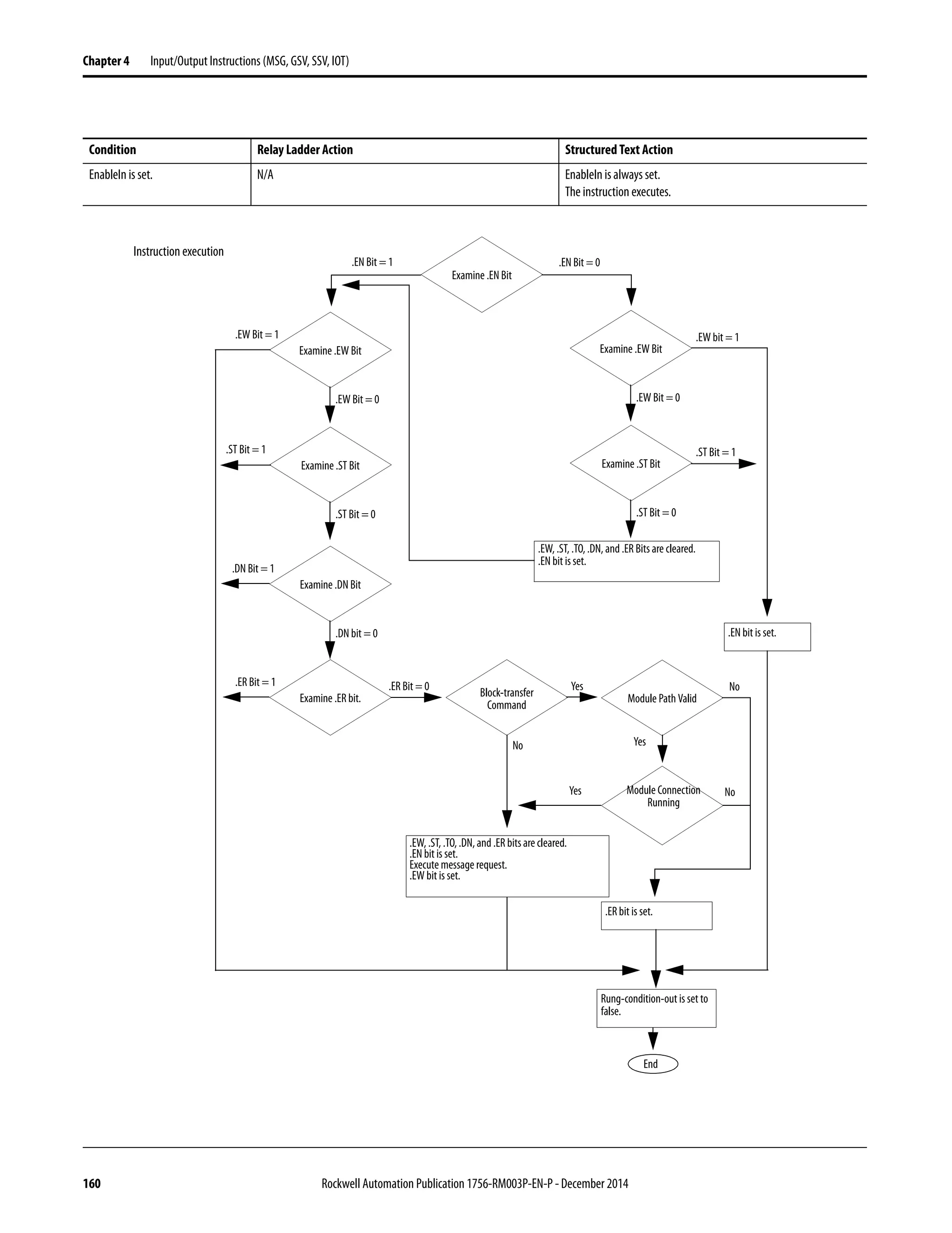
EnableIn is set N/A EnableIn is always set.
The instruction executes.
Instruction executes Get or set the specified value. Get or set the specified value.
Postscan The rung-condition-out is set to false. No action taken.](https://image.slidesharecdn.com/1756-rm003-en-p-150617024022-lva1-app6892/75/1756-rm003-en-p-190-2048.jpg)

![192 Rockwell Automation Publication 1756-RM003P-EN-P - December 2014
Chapter 4 Input/Output Instructions (MSG, GSV, SSV, IOT)
AddOnInstructionDefinition Attributes
The AddOnInstructionDefinition object lets you customize instructions for sets
of commonly-used logic, provides a common interface to this logic, and provides
documentation for the instruction.
For details, see the Logix5000 Controllers Add-On Instructions Programming
Manual, publication 1756-PM010.
Controller Attributes
The Controller object provides status information about controller execution.
Task 204
TimeSynchronization SeetheIntegratedArchitectureandCIPSyncConfiguration
Application Technique, publication IA-AT003.
WallClockTime 206
Table 6 - GSV/SSV Objects
Attribute Data Type Instruction
within
Standard Task
Instruction
within Safety
Task
Description
LastEditDate LINT GSV None Date and time stamp of thelast edit to an Add-On Instruction definition.
MajorRevision DINT GSV None Major revision number of the Add-On Instruction.
MinorRevision DINT GSV None Minor revision number of the Add-On Instruction.
Name String GSV GSV Name of the Add-On Instruction.
RevisionExtendedText String GSV None Text describing the revision of the Add-On Instruction.
SafetySignature
ID
DINT GSV None In a safety project, the ID number, date, and timestamp of an Add-On Instruction definition.
SignatureID DINT GSV None 32-bit identification number of an Add-On Instruction definition.
Vendor String GSV None Vendor that created the Add-On Instruction.
Attribute Data Type Instruction Description
Audit Value DINT[2], LINT GSV The audit value is a unique value that is generated when a project is downloaded to the controller or loaded from
removable storage. When a change is detected, this value is updated.
To specify which changes are monitored, use the ChangesToDetect attribute.
Note: We recommend using the DINT[2] data type to avoidlimitations when working with LINT data types in
Rockwell Automation controllers.
ChangesToDetect
See Table 4
DINT[2], LINT GSV, SSV Used to specify which changes are monitored. When a monitored change occurs, the Audit Value is updated.
Note: We recommend using the DINT[2] data type to avoidlimitations when working with LINT data types in
Rockwell Automation controllers.
CanUseRPIFrom
Producer
DINT GSV Identifies whether to use the RPI specified by the producer.
Value Meaning
0 Do not use the RPI specified by the producer
1 Use the RPI specified by the producer
ControllerLog
Execution
Modification
Count
DINT GSV
SSV
Number of controller log entries that originated from a program/task properties change, an online edit, or a
controller timeslice change. It can also be configured to include log entries originating from forces. The number will
be reset if RAM enters a bad state. The number is not capped at the largest DINT, and a rollover can occur.](https://image.slidesharecdn.com/1756-rm003-en-p-150617024022-lva1-app6892/75/1756-rm003-en-p-192-2048.jpg)

![194 Rockwell Automation Publication 1756-RM003P-EN-P - December 2014
Chapter 4 Input/Output Instructions (MSG, GSV, SSV, IOT)
ControllerDevice Attributes
The ControllerDevice object identifies the physical hardware of the controller.
Attribute Data Type Instruction Description
DeviceName SINT[33] GSV ASCIIstringthatidentifiesthecatalognumberofthecontrollerandmemoryboard.Thefirstbytecontainsacountof
the number of ASCII characters returned in the array string.
ProductCode INT GSV Identifies the type of controller:
Value Meaning
15 SoftLogix5800
49 PowerFlex® with DriveLogix5725
52 PowerFlex with DriveLogix5730
53 Emulator
54 1756-L61 ControlLogix
55 1756-L62 ControlLogix
56 1756-L63 ControlLogix
57 1756-L64 ControlLogix
64 1769-L31 CompactLogix
65 1769-L35E CompactLogix
67 1756-L61S GuardLogix
68 1756-L62S GuardLogix
69 1756-LSP GuardLogix
72 1768-L43 CompactLogix
74 1768-L45 CompactLogix
76 1769-L32C CompactLogix
77 1769-L32E CompactLogix
80 1769-L35CR CompactLogix
85 1756-L65 ControlLogix
86 1756-L63S GuardLogix
87 1769-L23E-QB1 CompactLogix
88 1769-L23-QBFC1 CompactLogix
89 1769-L23E-QBFC1 CompactLogix
92 1756-L71
93 1756-L72
94 1756-L73
95 1756-L74
96 1756-L75
106 1769-L30ER
107 1769-L33ER
108 1769-L36ERM
109 1769-L30ER-NSE
110 1769-L33ERM
146 1756-L7SP
147 1756-L72S
148 1756-L73S
149 1769-L24ER-QB1B
150 1769-L24ER-QBFC1B
151 1769-L27ERM-QBFC1B
153 1769-L16ER-BB1B
154 1769-L18ER-BB1B
155 1769-L18ERM-BB1B
156 1769-L30ERM
158 1756-L71S
ProductRev INT GSV Identifiesthecurrentproductrevision.Displayshouldbehexadecimal.Thelowbytecontainsthemajorrevision;the
high byte contains the minorrevision.
SerialNumber DINT GSV Serial number of the device. The serial number is assigned when the device is built.](https://image.slidesharecdn.com/1756-rm003-en-p-150617024022-lva1-app6892/75/1756-rm003-en-p-194-2048.jpg)

![196 Rockwell Automation Publication 1756-RM003P-EN-P - December 2014
Chapter 4 Input/Output Instructions (MSG, GSV, SSV, IOT)
CST Attributes
The coordinated system time (CST) object provides coordinated system time for
the devices in one chassis.
Attribute Data Type Instruction Description
CurrentStatus INT GSV Current status of the coordinated system time.
Bit Meaning
0 Timer hardware faulted: the device’s internal timer hardware is in a faulted state
1 Ramping enabled: the current value of the timer’s lower 16+ bits ramp up to
the requested value, rather than snap to the lower value.
2 System time master: the CST object is a master time source in the
ControlLogix system
3 Synchronized: the CST object’s 64-bit CurrentValue is synchronized by master
CST object via a system time update
4 Local network master: the CST object is the local network master time source
5 Relay mode: the CST object is acting in a time relay mode
6 Duplicate master detected: a duplicate local network time master was
detected.
This bit is always 0 for time-dependent nodes.
7 Unused
8 -9 00 = time dependent node
01 = time master node
10 = time relay node
11 = Unused
10-15 Unused
CurrentValue DINT[2] GSV Current value of the timer. DINT[0] contains the lower 32; DINT[1] contains the upper 32 bits. The timersource is
adjusted to match the value supplied in update services and from local communication network synchronization.
Theadjustmentis either arampingto therequestedvalueoranimmediatesetting to therequestvalue,as reported
in the CurrentStatus attribute.](https://image.slidesharecdn.com/1756-rm003-en-p-150617024022-lva1-app6892/75/1756-rm003-en-p-196-2048.jpg)
![Rockwell Automation Publication 1756-RM003P-EN-P - December 2014 197
Input/Output Instructions (MSG, GSV, SSV, IOT) Chapter 4
DF1 Attributes
The DF1 object provides an interface to the DF1 communication driver that you
can configure for the serial port.
Attribute Data Type Instruction Description
ACKTimeout DINT GSV The amount of time to wait for an acknowledgment to a message transmission (point-to-point and master only).
Valid value 0-32,767. Delay in counts of 20 msec periods. Default is 50 (1 second).
Diagnostic
Counters
INT[19] GSV Array of diagnostic counters for the DF1 communication driver.
Word offset DF1 point-to-point DF1 slaveMaster
0 Signature (0x0043) Signature (0x0042) Signature (0x0044)
1 Modem bits Modem bits Modem bits
2 Packets sent Packets sent Packets sent
3 Packets received Packets received Packets received
4 Undelivered packets Undelivered packets Undelivered packets
5 Unused Messages retried Messages retried
6 NAKsreceived NAKs received Unused
7 ENQs received Poll packets received Unused
8 Bad packets NAKed Bad packets not ACKed Bad packets not ACKed
9 No memory sent NAK No memory not ACKed Unused
10 Duplicate packets received Duplicate packets received Duplicate packets received
11 Bad characters received Unused Unused
12 DCD recoveries count DCD recoveries count DCD recoveries count
13 Lost modem count Lost modem count Lost modem count
14 Unused Unused Priority scan time maximum
15 Unused Unused Priority scan time last
16 Unused Unused Normal scan time maximum
17 Unused Unused Normal scant time last
18 ENQs sent Unused Unused
Duplicate
Detection
SINT GSV Enables duplicate message detection.
Value Meaning
0 Duplicate message detection disabled
Non zeroDuplicate message detection enabled
Embedded
ResponseEnable
SINT GSV Enables embedded response functionality (point-to-point only).
Value Meaning
0 Initiated only after one is received (default)
1 Enabledunconditionally
EnableStoreFwd SINT GSV Enables the store and forward behavior when receiving a message.
Value Meaning
0 Do not forward message
Non zero. See the store and forward table when receiving a message (default)
ENQTransmit
Limit
SINT GSV The number of inquiries (ENQs) to send after an ACK timeout (point-to-point only). Valid value 0-127. Default
setting is 3.
EOTSuppression SINT GSV Enable suppressing EOT transmissions in response to poll packets (slave only).
Value Meaning
0 EOT suppression disabled (disabled)
Non zeroEOT suppression enabled
ErrorDetection SINT GSV Specifies the error-detection scheme.
Value Meaning
0 BCC (default)
1 CRC
MasterMessageTransmit SINT GSV Current value of the master message transmission (master only).
Value Meaning
0 Between station polls (default)
1 In poll sequence (in place of master’s station number)
MaxStation
Address
SINT GSV Current value (0...31) of the maximum node address on a DH-485 network. Default is 31.
NAKReceiveLimit SINT GSV The number of NAKs received in response to a message before stopping transmission (point-to-point
communication only). Valid value 0...127. Default is 3.](https://image.slidesharecdn.com/1756-rm003-en-p-150617024022-lva1-app6892/75/1756-rm003-en-p-197-2048.jpg)

![Rockwell Automation Publication 1756-RM003P-EN-P - December 2014 199
Input/Output Instructions (MSG, GSV, SSV, IOT) Chapter 4
FaultLog Attributes
The FaultLog object provides fault information about the controller.
Message Attributes
You can access the Message object through the GSV/SSV instructions. Specify
the message tag name to determine which Message object you want. The Message
object provides an interface to setup and trigger peer-to-peer communications.
This object replaces the MG data type of the
PLC-5 processor.
PendingStation
Address
INT SSV Pending value for the StationAddress attribute.
PendingToken
HoldFactory
SINT SSV Pending value for the TokenHoldFactor attribute.
PendingTransmitRetries SINT SSV Pending value for the TransmitRetries attribute.
Attribute Data Type Instruction Description
Attribute Data Type Instruction Description
MajorEvents INT GSV
SSV
How many major faults have occurred since the last time this counter was reset.
MajorFaultBits DINT GSV
SSV
Individual bits indicate the reason for the current major fault.
Bit Meaning
1
3
4
5
6
7
8
11
Power loss
I/O
Instruction execution (program)
Fault Handler
Watchdog
Stack
Modechange
Motion
MinorEvents INT GSV
SSV
How many minor faults have occurred since the last time this counter was reset.
MinorFaultBits DINT GSV
SSV
Individual bits indicate the reason for the current minor fault.
Bit
4
6
9
10
Meaning
Instruction execution (program)
Watchdog
Serial port
Battery/Energy Storage Module (ESM)(1)
(1) Battery for 1756-L6x, 1769-L2x, and 1769-L3x controllers. ESM for 1756-L7x controllers and CompactLogix 5370 series controllers.
Attribute Data Type Instruction Description
ConnectionPath SINT[130] GSV
SSV
Data to setup the connection path. The first two bytes (low byte and high byte) arethe length in bytes of the
connection path.
ConnectionRate DINT GSV
SSV
Requested packet rate of the connection.](https://image.slidesharecdn.com/1756-rm003-en-p-150617024022-lva1-app6892/75/1756-rm003-en-p-199-2048.jpg)
![Rockwell Automation Publication 1756-RM003P-EN-P - December 2014 201
Input/Output Instructions (MSG, GSV, SSV, IOT) Chapter 4
Program Attributes
The Program object provides status information about a program. Specify the
program name to determine the Program object you want.
ForceStatus INT GSV Specifies the status of forces.
Bit Meaning
0 Forces installed (1=yes, 0-no)
1 Forces enabled (1=yes, 0=no)
Instance DINT GSV Provides the instance number of this module object.
LEDStatus INT GSV Specifies the current state of the I/O status indicator on the front of the controller.(1)
Value Meaning
0 Status indicator off: No Module objects are configured for the controller.
(There are no modules in the I/O Configuration section of the controller organizer.)
1 Flashing red: None of the Module objects are Running.
2 Flashing green: At least one Module object is not Running.
3 Solid green: All the Module objects are Running.
You do not enter an object name with this attribute because this attribute applies to the entire collection of
modules.
Mode INT GSV
SSV
Specifies the current mode of the Module object.
Bit Meaning
0 If set, causes a major fault to be generated if any of the Module object
connections fault while the controller is in Run mode.
2 If set, causes the Module object to enter Inhibited stateafter shutting
down all the connections to the module.
Path SINT
Array
GSV Specifies the path to the module being referenced. This is a new attribute starting in version 24 software.
Byte Meaning
0-1 Length of the path in bytes. If 0, length of theSINT array is insufficient to hold the returned module
path.
If SINT array length is insufficient to hold the path, the array is zeroed out, and a minor fault is logged.
(1) The 1756-L7x controllers do not have a status indicator display on the front of the controller, but do use this functionality.
Attribute Data Type Instruction Description
Attribute Data Type Instruction
within
Standard Task
Instruction
within Safety
Task
Description
DisableFlag SINT GSV
SSV
None Controls this program’s execution.
Value Meaning
0 Execution enabled
non-zero) Execution disabled
DINT GSV GSV A non-zero value will disable.
LastScanTime DINT GSV
SSV
None Time it took to execute this program the last time it was executed. Time is in microseconds.
MajorFault
Record
DINT[11] GSV
SSV
GSV
SSV
Records major faults for this program
We recommend that you create a user-defined structure to simplify access to the MajorFaultRecord attribute:
Name Data Type Style Description
TimeLow DINT Decimal Lower 32 bits of fault timestamp value
TimeHigh DINT Decimal Upper 32 bits of fault timestamp value
Type INT Decimal Fault type (program, I/O, and so forth)
Code INT Decimal Unique code for the fault (depends on fault type)
Info DINT[8] Hexadecimal Fault specific information (depends on fault type and code)](https://image.slidesharecdn.com/1756-rm003-en-p-150617024022-lva1-app6892/75/1756-rm003-en-p-201-2048.jpg)
![202 Rockwell Automation Publication 1756-RM003P-EN-P - December 2014
Chapter 4 Input/Output Instructions (MSG, GSV, SSV, IOT)
Routine Attributes
The Routine object provides status information about a routine. Specify the
routine name to determine which Routine object that you want.
MinorFault
Record
DINT[11] GSV
SSV
GSV
SSV
Records minor faults for this program
We recommend that you create a user-defined structure to simplify access to the MinorFaultRecord attribute:
Name Data Type Style Description
TimeLow DINT Decimal Lower 32 bits of fault timestamp value
TimeHigh DINT Decimal Upper 32 bits of fault timestamp value
Type INT Decimal Fault type (program, I/O, and so forth)
Code INT Decimal Unique code for the fault (depends on fault type)
Info DINT[8] Hexadecimal Fault specific information (depends on fault type and code)
MaxScanTime DINT GSV
SSV
None Maximum recorded execution time for this program. Time is in microseconds.
Name String GSV GSV Name of the program.
Attribute Data Type Instruction
within
Standard Task
Instruction
within Safety
Task
Description
Attribute Data Type Instruction
within
Standard Task
Instruction
within Safety
Task
Description
Instance DINT GSV GSV Provides the instance number for this routine object. Valid values are 0…65,535.
Name String GSV GSV Name of the routine.
SFCPaused INT GSV None In an SFC routine, indicates whether the SFC is paused.
Value Meaning
0 SFC is not paused
1 SFC is paused
SFCResuming INT GSV
SSV
None In an SFC routine, indicates whether the SFC is resuming execution.
Value Meaning
0 SFC is not executing. This attribute is automatically set to 0 at the end of a scan in
which the chart was executed
1 SFCis executing.Stepandactiontimers willretaintheirprevious value if configured
to do so. This attribute is automatically set to 1 on the first scan after a chart is
unpaused.](https://image.slidesharecdn.com/1756-rm003-en-p-150617024022-lva1-app6892/75/1756-rm003-en-p-202-2048.jpg)
![Rockwell Automation Publication 1756-RM003P-EN-P - December 2014 203
Input/Output Instructions (MSG, GSV, SSV, IOT) Chapter 4
Safety Attributes
The Safety Controller object provides safety status and safety signature
information. The SafetyTask and SafetyFaultRecord attributes can capture
information about non-recoverable faults.
See the GuardLogix Controllers User Manual, publication 1756-UM020.
SerialPort Attributes
The SerialPort object provides an interface to the serial communication port.
Attribute Data Type Instruction
within
Standard Task
Instruction
within Safety
Task
Description
SafetyLocked SINT GSV None Indicates whether the controller is safety locked or unlocked.
SafetyStatus INT GSV None Specifies the safety status as:
Value Meaning
1000000000000000 Safety task OK.
1000000000000001 Safety task inoperable.
00000000000000000 Partner missing.
00000000000000001 Partner unavailable.
00000000000000010 Hardware incompatible.
00000000000000011 Firmware incompatible.
SafetySignature
Exists
SINT GSV GSV Indicates whether the safety task signature is present.
SafetySignature
ID
DINT GSV None 32-bit identification number.
SafetySignature String GSV None 32-bit identification number.
SafetyTaskFault
Record
DINT[11] GSV None Records safety task faults.
Attribute Data Type Instruction Description
BaudRate DINT GSV Specifies the baud rate. Valid values are 110, 300, 600, 1200, 2400, 4800, 9600, and 19200 (default).
ComDriverID SINT GSV Specifies the specific driver.
Value Meaning
0xA2 DF1 (default)
0xA3 ASCII
DataBits SINT GSV Specifies the number of bits of data per character.
Value Meaning
7 7 data bits (ASCII only)
8 8 data bits (default)
DCDDelay INT GSV Specifies the amountoftime to wait forthe datacarrierdetect (DCD) tobecome lowbefore erroring thepacket. The
delay is in counts of 1 s packets. Default is 0 counter.
Parity SINT GSV Specifies the parity.
Value Meaning
0 No parity (no default)
1 Odd parity (ASCII only)
2 Even parity
RTSOffDelay INT GSV Amount of time to delay turning off the RTS line after the last character has been transmitted. Valid value
0...32,767. Delay in counts of 20msec periods. The default is 0 msec.
RTSSendDelay INT GSV Amount of time to delaytransmitting the first character of a message after turning on the RTS line. Valid value
0...32,767. Delay in counts of 20msec periods. The default is 0 msec.](https://image.slidesharecdn.com/1756-rm003-en-p-150617024022-lva1-app6892/75/1756-rm003-en-p-203-2048.jpg)
![204 Rockwell Automation Publication 1756-RM003P-EN-P - December 2014
Chapter 4 Input/Output Instructions (MSG, GSV, SSV, IOT)
Task Attributes
The Task object provides status information about a task. Specify the task name
to determine which Task object that you want.
StopBits SINT GSV Specifies the number of stop bits.
Value Meaning
1 1 stop bit (default)
2 2 stop bits (ASCII only)
PendingBaudRate DINT SSV Pending value for the BaudRate attribute.
PendingCOM
DriverID
SINT SSV Pending value for the COMDriverID attribute.
PendingDataBits SINT SSV Pending value for the DataBits attribute.
PendingDCD
Delay
INT SSV Pending value for the DCDDelay attribute.
PendingParity SINT SSV Pending value for the Parity attribute.
PendingRTSOff
Delay
INT SSV Pending value for the RTSOffDelay attribute.
PendingRTSSendDelay INT SSV Pending value for the RTSSendDelay attribute.
PendingStopBits SINT SSV Pending value for the StopBits attribute.
Attribute Data Type Instruction Description
Attribute Data Type Instruction
within
Standard Task
Instruction
within Safety
Task
Description
DisableUpdate
Outputs
DINT GSV
SSV
None Enables or disables the processing of outputs at theend of a task.
Value Meaning
0 Enable the processing of outputs at the end of the task
Non zero Disable the processing of outputs at the end of the task
EnableTimeOut DINT GSV
SSV
None Enables or disables the timeout function of an event task.
Value Meaning
0 Disable the timeout function
Non zero Enable the timeout function
InhibitTask DINT GSV
SSV
None Preventsthetaskfromexecuting.Ifataskisinhibited,thecontrollerstillprescansthetaskwhen
the controller transitions from program to run or test mode.
Value Meaning
0 Enable the task 0 (default)
Non zero Inhibit (disable) the task
Instance DINT GSV GSV Provides the instance number of this task object. Valid values are 0...31.
LastScanTime DINT GSV
SSV
None Time it took to execute this task the last time it was executed. Time is in microseconds.
MaximumInterval DINT[2] GSV
SSV
None The maximum time interval between successive executions of the task. DINT[0] contains the
lower 32 bits of the value; DINT[1] contains the upper 32 bits of the value. A value of 0 indicates
1 or less executions of the task.
MaximumScan
Time
DINT GSV
SSV
None Maximum recorded execution time for this program. Time is in microseconds.
MinimumInterval DINT[2] GSV
SSV
None The minimum time interval between successive executions of the task. DINT[0] contains the
lower 32 bits of the value; DINT[1] contains the upper 32 bits of the value. A value of 0 indicates
1 or less executions of the task.
Name String GSV GSV Name of the task.](https://image.slidesharecdn.com/1756-rm003-en-p-150617024022-lva1-app6892/75/1756-rm003-en-p-204-2048.jpg)
![Rockwell Automation Publication 1756-RM003P-EN-P - December 2014 205
Input/Output Instructions (MSG, GSV, SSV, IOT) Chapter 4
OverlapCount DINT GSV
SSV
GSV
SSV
Number of times that the task was triggered while it was still executing. Valid for an event or a
periodic task. To clear the count, set the attribute to 0.
Priority INT GSV
SSV
GSV Relative priority of this task as compared to the other tasks. Valid values 0...15.
Rate DINT GSV
SSV
GSV The time interval between executions of the task. Time is in microseconds.
StartTime DINT[2] GSV
SSV
None Value of WALLCLOCKTIME when the last execution of the task was started. DINT[0] contains the
lower 32 bits of the value; DINT[1] contains the upper 32 bits of the value.
Status DINT GSV
SSV
None Status informationabout the task.Oncethe controller sets oneofthesebits,youmustmanually
clear the bit.
Bit Meaning
0 An EVENT instruction triggered the task (event task only)
1 A timeout triggered the task (event task only)
2 An overlap occurred for this task
Watchdog DINT GSV
SSV
GSV Time limit for execution of all programs associated with this task. Time is in microseconds.
If you enter 0, these values are assigned:
Time Task Type
0.5 sec Periodic
5.0 sec Continuous
Attribute Data Type Instruction
within
Standard Task
Instruction
within Safety
Task
Description](https://image.slidesharecdn.com/1756-rm003-en-p-150617024022-lva1-app6892/75/1756-rm003-en-p-205-2048.jpg)
![206 Rockwell Automation Publication 1756-RM003P-EN-P - December 2014
Chapter 4 Input/Output Instructions (MSG, GSV, SSV, IOT)
WallClockTime Attributes
The WallClockTime object provides a timestamp that the controller can use for
scheduling.
Attribute Data Type Instruction Description
ApplyDST SINT GSV
SSV
Identifies whether to enable daylight savings time.
Value Meaning
0 Do not adjust for daylight savings time
non zero Adjust for daylight savings time
CSTOffset DINT[2] GSV
SSV
Positive offset from the CurrentValue of the CST object (coordinated system time, see page 196).
DINT[0] contains the lower 32 bits of the value; DINT[1] contains the upper32 bits of the value.Value
in μs. The default is 0.
CurrentValue DINT[2] GSV
SSV
Current value of the wall clock time. DINT[0] contains the lower 32 bits of thevalue; DINT[1] contains
the upper 32 bits of the value. The value is the number of microseconds that have elapsed since 0000
hours 1 January 1972. The CST and WALLCLOCKTIME objects are mathematically related in the
controller. For example, if you add the CST CurrentValue and the WALLCLOCKTIME CTSOffset, the result
is the WALLCLOCKTIME CurrentValue.
DateTime DINT[7] GSV
SSV
The date and time.
Value Meaning
DINT[0] Year
DINT[1] Month (1...12)
DINT[2] Day (1...31)
DINT[3] Hour (0...23)
DINT[4] Minute (0...59)
DINT[5] Seconds (0...59)
DINT[6] Microseconds (0...999,999)
DSTAdjustment INT GSV
SSV
The number of minutes to adjust for daylight saving time.
LocalDateTime DINT[7] GSV
SSV
Current adjusted local time.
Value Meaning
DINT[0] Year
DINT[1] Month (1...12)
DINT[2] Day (1...31)
DINT[3] Hour (0...23)
DINT[4] Minute (0...59)
DINT[5] Seconds (0...59)
DINT[6] Microseconds (0...999,999)
TimeZoneString INT GSV
SSV
Time zone for the time value.](https://image.slidesharecdn.com/1756-rm003-en-p-150617024022-lva1-app6892/75/1756-rm003-en-p-206-2048.jpg)


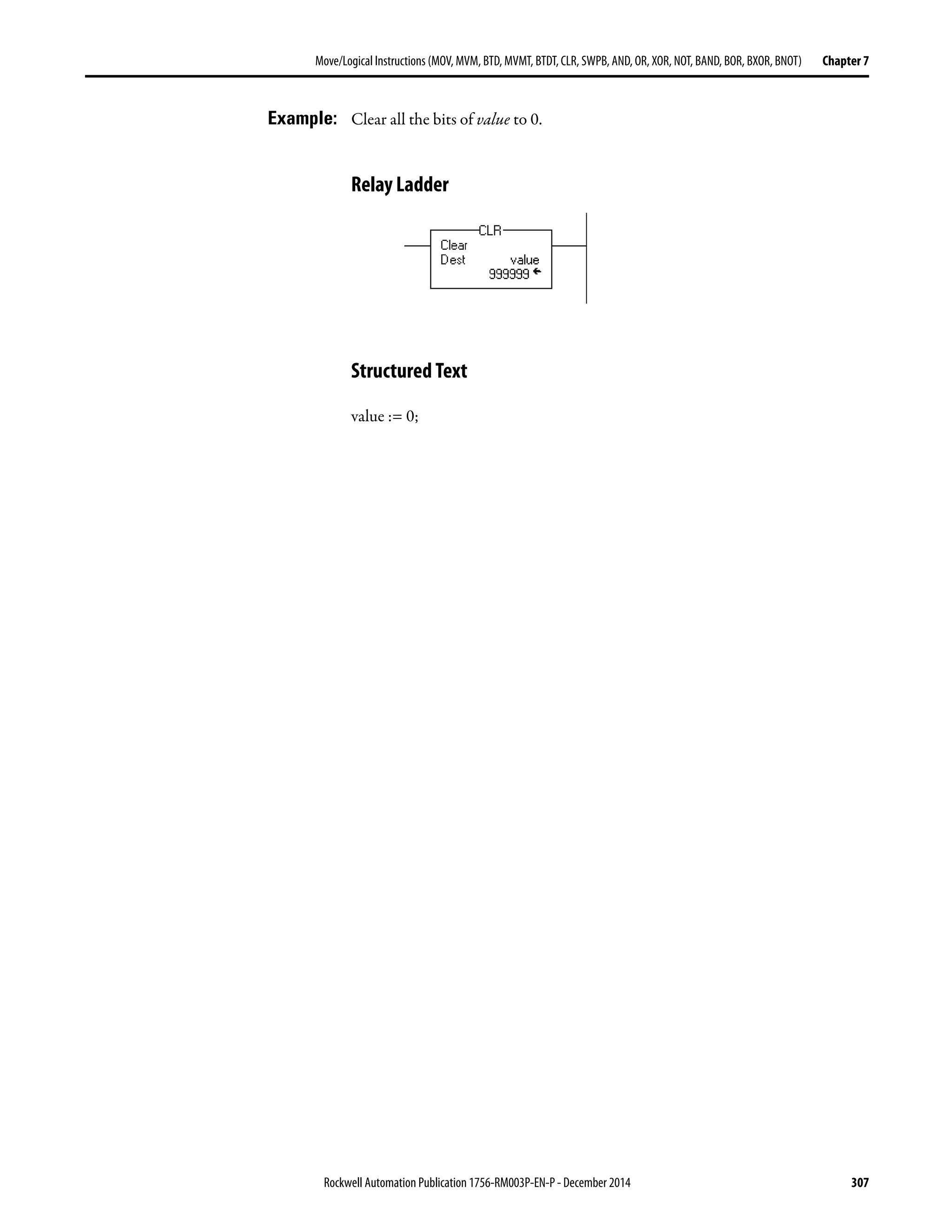
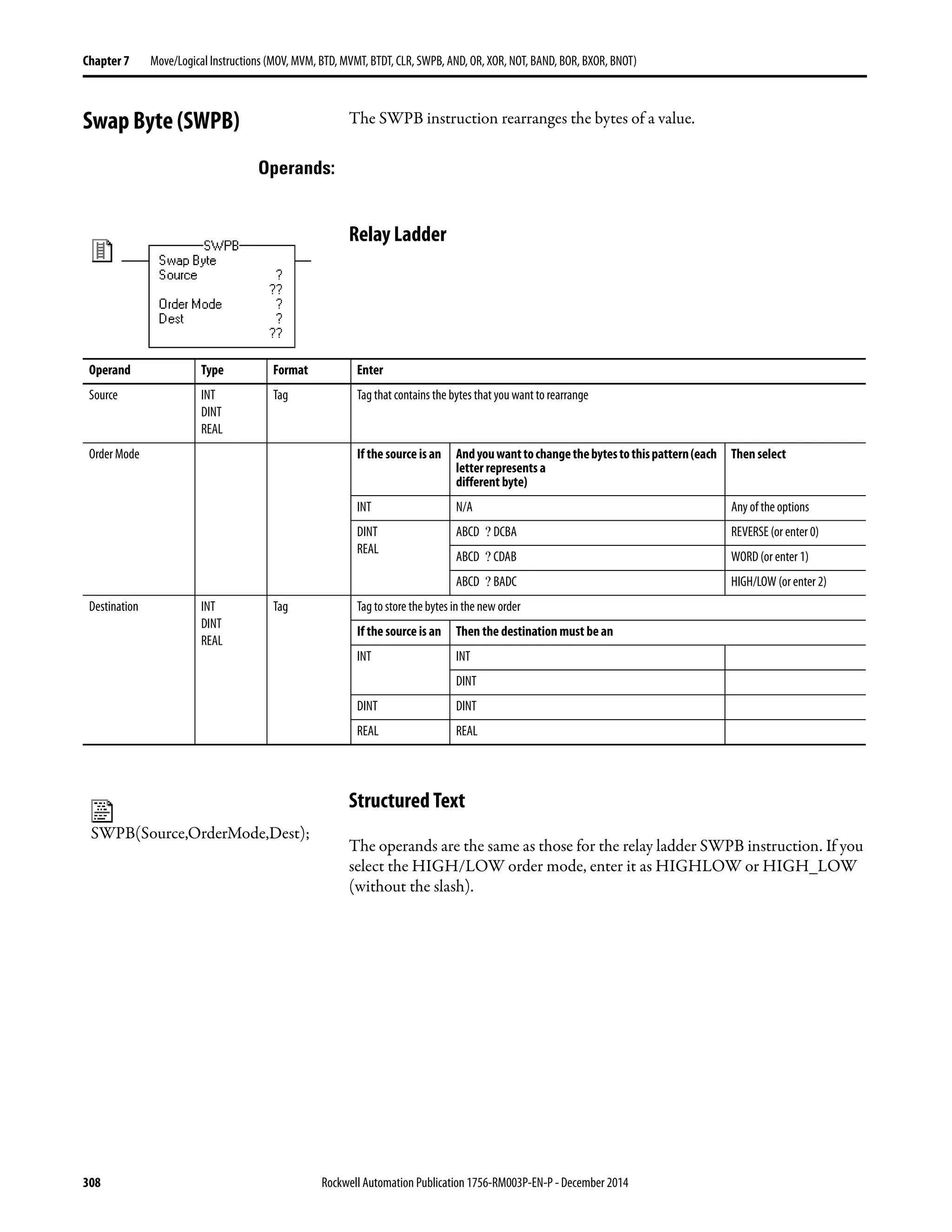
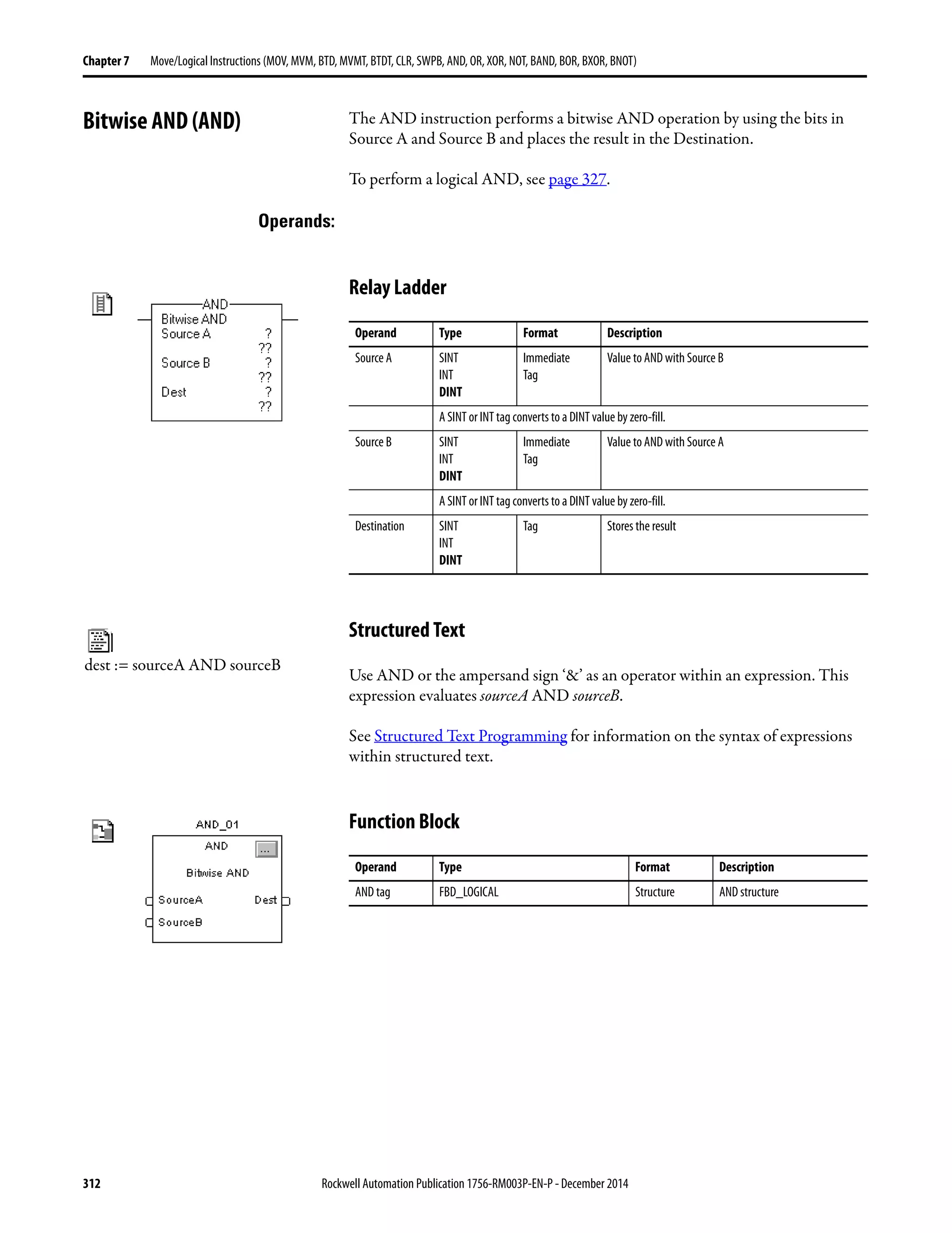
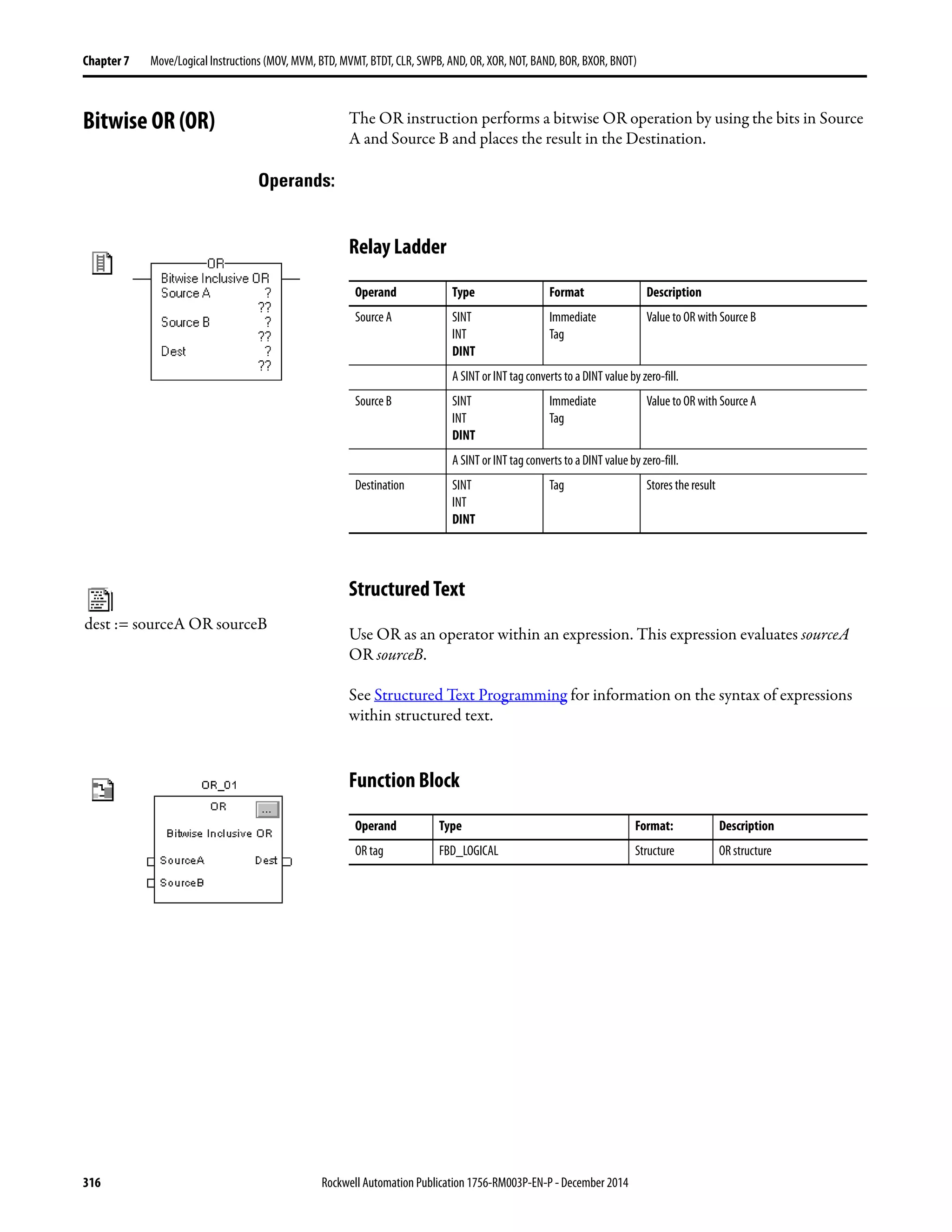
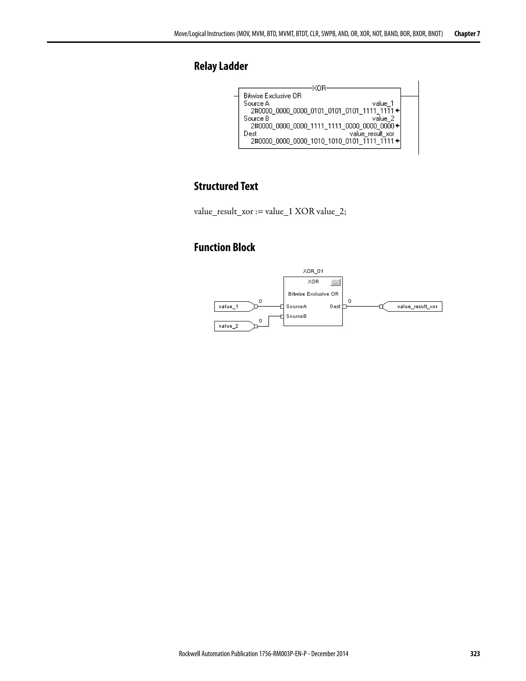
![Rockwell Automation Publication 1756-RM003P-EN-P - December 2014 309
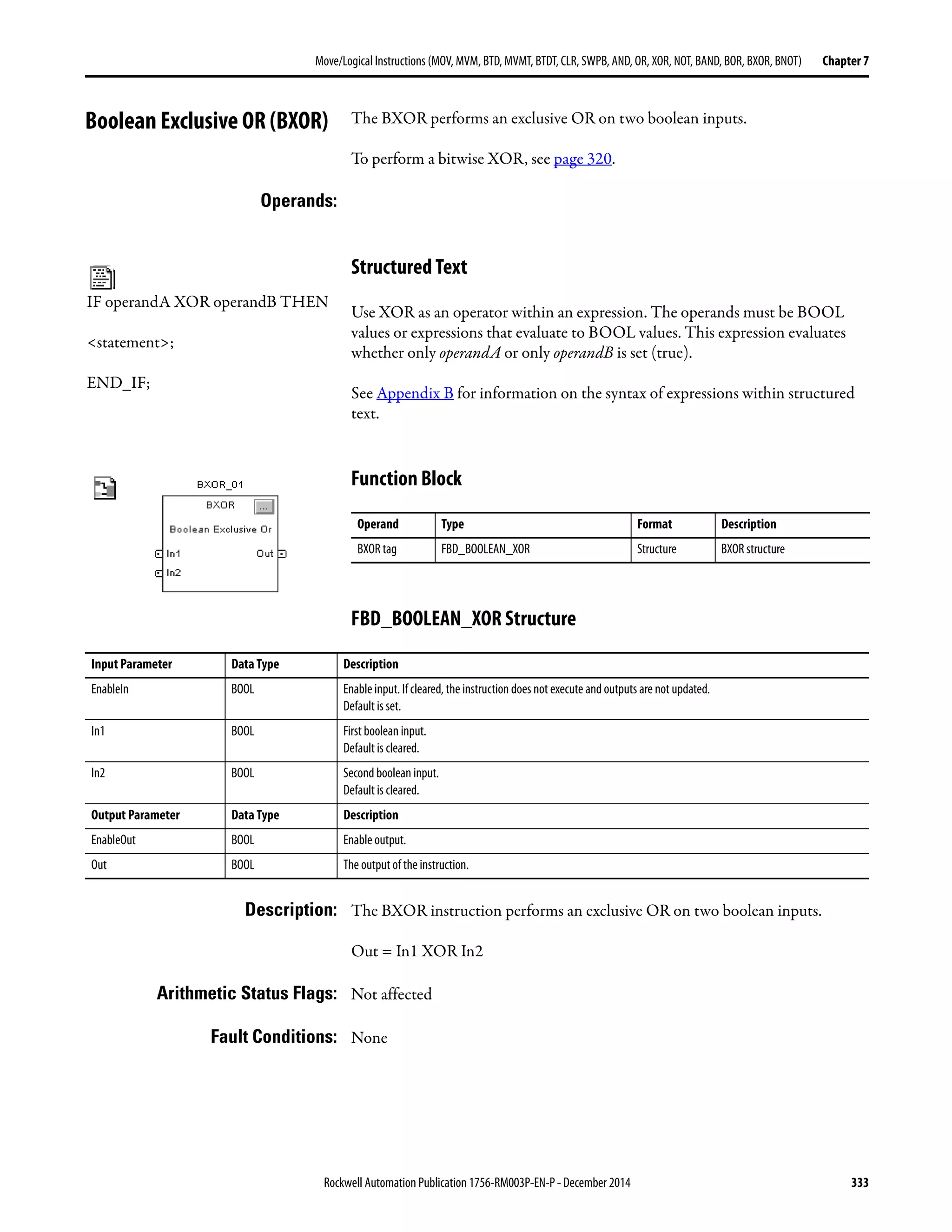
Move/Logical Instructions (MOV, MVM, BTD, MVMT, BTDT,CLR, SWPB, AND, OR, XOR, NOT, BAND, BOR, BXOR, BNOT) Chapter 7
Description: The SWPB instruction rearranges the order of the bytes of the Source. It places
the result in the Destination.
When you read or write ASCII characters, you typically do not need to swap
characters. The ASCII read and write instructions (ARD, ARL, AWA, AWT)
automatically swap characters, as shown below.
Arithmetic Status Flags: Not affected
Fault Conditions: None
Execution:
Example 1: The three SWPB instructions each reorder the bytes of DINT_1 according to a
different order mode. The display style is ASCII, and each character represents
one byte. Each instruction places the bytes, in the new order, in a different
Destination.
Relay Ladder
42969
42968
B A
Tag Name Value Style Type
bar_code[0] AB ASCII INT
A B
bar code reader
Condition Relay Ladder Action Structured Text Action
Prescan The rung-condition-out is set to false. No action taken
Rung-condition-in is false The rung-condition-out is set to false. N/A
Rung-condition-in is true The rung-condition-out is set to true. N/A
EnableIn is set N/A EnableIn is always set.
The instruction executes.
Instruction execution The instruction rearranges the specified bytes. The instruction rearranges the specified bytes.
Postscan The rung-condition-out is set to false. No action taken.](https://image.slidesharecdn.com/1756-rm003-en-p-150617024022-lva1-app6892/75/1756-rm003-en-p-309-2048.jpg)
![310 Rockwell Automation Publication 1756-RM003P-EN-P - December 2014
Chapter 7 Move/Logical Instructions (MOV, MVM, BTD, MVMT, BTDT, CLR, SWPB, AND, OR, XOR, NOT, BAND, BOR, BXOR, BNOT)
Structured Text
SWPB(DINT_1,REVERSE,DINT_1_reverse);
SWPB(DINT_1,WORD,DINT_1_swap_word);
SWPB(DINT_1,HIGHLOW,DINT_1_swap_high_low);
Example 2: The following example reverses the bytes in each element of an array. For an
RSLogix 5000 project that contains this example, open the
RSLogix 5000ProjectsSamples folder, Swap_Bytes_in_Array.ACD file.
1. Initialize the tags. The SIZE instruction finds the number of elements in
array and stores that value in array_length. A subsequent instruction uses
this value to determine when the routine has acted on all the elements in
the array.
2. Reverse the bytes in one element of array.
• The SWPB instruction reverses the bytes of the element number that is
indicated by the value of index. For example, when index equals 0, the
SWPB instruction acts on array[0].
• The ADD instruction increments index. The next time the instruction
executes, the SWPB instruction acts on the next element in array.
3. Determine when the SWPB instruction has acted on all the elements in
the array.
• If index is less then the number of elements in the array (array_length),
then continue with the next element in the array.
• If index equals array_length, then the SWPB has acted on all the elements
in the array.](https://image.slidesharecdn.com/1756-rm003-en-p-150617024022-lva1-app6892/75/1756-rm003-en-p-310-2048.jpg)
![Rockwell Automation Publication 1756-RM003P-EN-P - December 2014 311
Move/Logical Instructions (MOV, MVM, BTD, MVMT, BTDT,CLR, SWPB, AND, OR, XOR, NOT, BAND, BOR, BXOR, BNOT) Chapter 7
Relay Ladder
Structured Text
index := 0;
SIZE (array[0],0,array_length);
REPEAT
SWPB(array[index],REVERSE,array_bytes_reverse[index]);
index := index + 1;
UNTIL(index >= array_length)END_REPEAT;
Initialize the tags.
Reverse the bytes.
Determine whetherthe SWPB instruction has actedon all the elements in the array.](https://image.slidesharecdn.com/1756-rm003-en-p-150617024022-lva1-app6892/75/1756-rm003-en-p-311-2048.jpg)


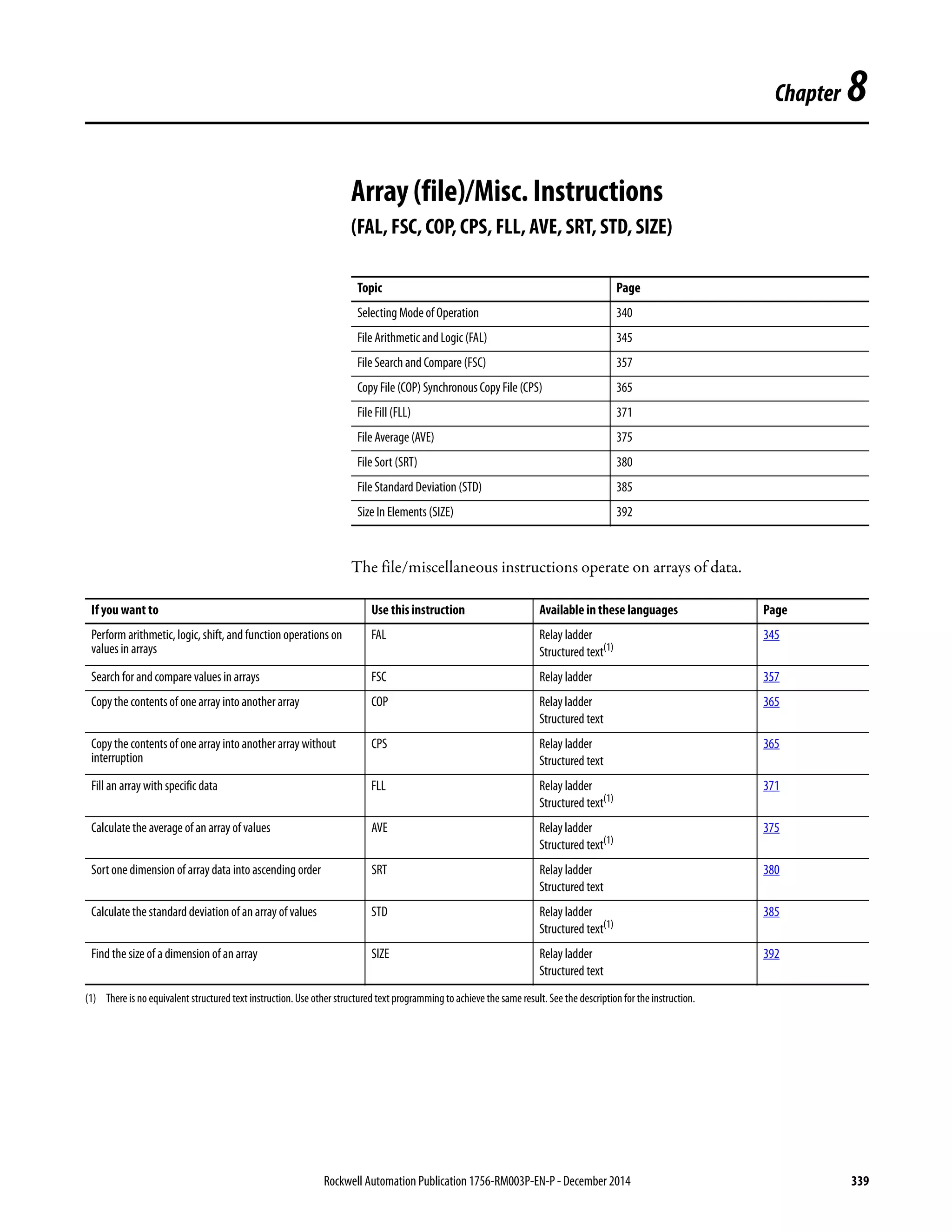


![Rockwell Automation Publication 1756-RM003P-EN-P - December 2014 345
Array (file)/Misc. Instructions (FAL, FSC, COP, CPS, FLL, AVE, SRT, STD, SIZE) Chapter 8
File Arithmetic and Logic
(FAL)
The FAL instruction performs copy, arithmetic, logic, and function operations
on data stored in an array.
Operands:
Relay Ladder
Structured Text
Structured text does not have an FAL instruction, but you can achieve the same
results by using a SIZE instruction and a FOR...DO or other loop construct.
SIZE(destination,0,length-1);
FOR position = 0 TO length DO
destination[position] := numeric_expression;
END_FOR;
See Structured Text Programming for information on the syntax of constructs
within structured text.
Operand Type Format Description
Control CONTROL Tag Control structure for the operation
Length DINT Immediate Number of elements in the array to
be manipulated
Position DINT Immediate Current element in array
Initial value is typically 0
Mode DINT Immediate How to distribute the operation
Select INC, ALL, or enter a number
Destination SINT
INT
DINT
REAL
Tag Tag to store the result
Expression SINT
INT
DINT
REAL
Immediate
Tag
An expression consisting of tags and/or
immediate values separated by operators
A SINT or INT tag converts to a DINT value by sign-extension.](https://image.slidesharecdn.com/1756-rm003-en-p-150617024022-lva1-app6892/75/1756-rm003-en-p-345-2048.jpg)


![352 Rockwell Automation Publication 1756-RM003P-EN-P - December 2014
Chapter 8 Array (file)/Misc. Instructions (FAL, FSC, COP, CPS, FLL, AVE, SRT, STD, SIZE)
Example 1: When enabled, the FAL instruction copies each element of array_2 into the same
position within array_1.
Example 2: When enabled, the FAL instruction copies value_1 into the first 10 positions of
the second dimension of array_2.
Example 3: Each time the FAL instruction is enabled, it copies the current value of array_1 to
value_1. The FAL instruction uses incremental mode, so only one array value is
copied each time the instruction is enabled. The next time the instruction is
enabled, the instruction overwrites value_1 with the next value in array_1.
Example 4: When enabled, the FAL instruction adds value_1 and value_2 and stores the
result in the current position of array_1.
Array-to-Array Copy
Expression:
array_2[control_2.pos]
Destination:
array_1[control_2.pos]
Element-to-Array Copy
Expression:
value_1
Destination:
array_2[0,control_2.pos]
Array-to-Element Copy
Expression:
array_1[control_1.pos]
Destination:
value_1
Arithmetic Operation: (Element + Element) to Array
Expression:
value_1+ value_2
Destination:
array_1[control_1.pos]](https://image.slidesharecdn.com/1756-rm003-en-p-150617024022-lva1-app6892/75/1756-rm003-en-p-352-2048.jpg)
![Rockwell Automation Publication 1756-RM003P-EN-P - December 2014 353
Array (file)/Misc. Instructions (FAL, FSC, COP, CPS, FLL, AVE, SRT, STD, SIZE) Chapter 8
Example 5: When enabled, the FAL instruction divides the value in the current position of
array_2 with the value in the current position of array_3 and stores the result in
the current position of array_1.
Example 6: When enabled, the FAL instruction adds the value at the current position in
array_1 to value_1 and stores the result in the current position in array_3. The
instruction must execute 10 times for the entire array_1 and array_3 to be
manipulated.
Arithmetic Operation: (Array / Array) to Array
Expression:
array_2[control_2.pos]/array_3[control_2.pos]
Destination:
array_1[control_2.pos]
Arithmetic Operation: (Array + eEement) to Array
Expression:
array_1[control_1.pos]+value_1
Destination:
array_3[control_1.pos]](https://image.slidesharecdn.com/1756-rm003-en-p-150617024022-lva1-app6892/75/1756-rm003-en-p-353-2048.jpg)
![354 Rockwell Automation Publication 1756-RM003P-EN-P - December 2014
Chapter 8 Array (file)/Misc. Instructions (FAL, FSC, COP, CPS, FLL, AVE, SRT, STD, SIZE)
Example 7: Each time the FAL instruction is enabled, it adds value_1 to the current value of
array_1 and stores the result in value_2. The FAL instruction uses incremental
mode, so only one array value is added to value_1 each time the instruction is
enabled. The next time the instruction is enabled, the instruction overwrites
value_2.
Example 8: When enabled, the FAL instruction multiplies the current value of array_1 by the
current value of array_3 and stores the result in value_1. The FAL instruction
uses incremental mode, so only one pair of array values is multiplied each time the
instruction is enabled. The next time the instruction is enabled, the instruction
overwrites value_1.
Arithmetic Operation: (Element + Array) to Element
Expression:
value_1+array_1[control_1.pos]
Destination:
value_2
Arithmetic Operation: (Array ∗ Array) to Element
Expression:
array_1[control_1.pos]* array_3[control_1.pos]
Destination:
value_1](https://image.slidesharecdn.com/1756-rm003-en-p-150617024022-lva1-app6892/75/1756-rm003-en-p-354-2048.jpg)


![368 Rockwell Automation Publication 1756-RM003P-EN-P - December 2014
Chapter 8 Array (file)/Misc. Instructions (FAL, FSC, COP, CPS, FLL, AVE, SRT, STD, SIZE)
Relay Ladder
Structured Text
COP(array_4[0],array_5[0],10);
Example 2: When enabled, the COP instruction copies the structure timer_1 into element 5
of array_timer. The instruction copies only one structure to one array element.
Relay Ladder
Structured Text
COP(timer_1,array_timer[5],1);](https://image.slidesharecdn.com/1756-rm003-en-p-150617024022-lva1-app6892/75/1756-rm003-en-p-368-2048.jpg)
![Rockwell Automation Publication 1756-RM003P-EN-P - December 2014 369
Array (file)/Misc. Instructions (FAL, FSC, COP, CPS, FLL, AVE, SRT, STD, SIZE) Chapter 8
Example 3: The project_data array (100 elements) stores a variety of values that change at
different times in the application. To send a complete image of project_data at one
instance in time to another controller, the CPS instruction copies project_data to
produced_array.
• While the CPS instruction copies the data, no I/O updates or other tasks
can change the data.
• The produced_array tag produces the data on a ControlNet network for
consumption by other controllers.
• To use the same image of data (that is, a synchronized copy of the data), the
consuming controller (s) uses a CPS instruction to copy the data from the
consumed tag to another tag for use in the application.
Relay Ladder
Structured Text
CPS(project_data[0],produced_array[0],100);
Example 4: Local:0:I.Data stores the input data for the DeviceNet network that is connected
to the 1756-DNB module in slot 0. To synchronize the inputs with the
application, the CPS instruction copies the input data to input_buffer.
• While the CPS instruction copies the data, no I/O updates can change the
data.
• As the application executes, it uses for its inputs the input data in
input_buffer.
Relay Ladder
Structured Text
CPS(Local:0:I.Data[0],input_buffer[0],20);](https://image.slidesharecdn.com/1756-rm003-en-p-150617024022-lva1-app6892/75/1756-rm003-en-p-369-2048.jpg)
![370 Rockwell Automation Publication 1756-RM003P-EN-P - December 2014
Chapter 8 Array (file)/Misc. Instructions (FAL, FSC, COP, CPS, FLL, AVE, SRT, STD, SIZE)
Example 5: This example initializes an array of timer structures. When enabled, the MOV
instructions initialize the .PRE and .ACC values of the first array_timer element.
When enabled, the COP instruction copies a contiguous block of bytes, starting
at array_timer[0]. The length is nine timer structures.
Relay Ladder
Structured Text
IF S:FS THEN
array_timer[0].pre := 500;
array_timer[0].acc := 0;
COP(array_timer[0],array_timer[1],10);
END_IF;
Array_timer[0] First the instruction copies timer[0] values
to timer[1].
Array_timer[1] Thentheinstructioncopiestimer[1]values
to timer[2].
Array_timer[2] Thentheinstructioncopiestimer[2]values
to timer[3].
Array_timer[3] Thentheinstructioncopiestimer[3]values
to timer[4].
Array_timer[4]
•
•
•
Array_timer[9] Finally, the instruction copies timer[9]
values to timer[10].
Array_timer[10]](https://image.slidesharecdn.com/1756-rm003-en-p-150617024022-lva1-app6892/75/1756-rm003-en-p-370-2048.jpg)
![Rockwell Automation Publication 1756-RM003P-EN-P - December 2014 371
Array (file)/Misc. Instructions (FAL, FSC, COP, CPS, FLL, AVE, SRT, STD, SIZE) Chapter 8
File Fill (FLL) The FLL instruction fills elements of an array with the Source value. The Source
remains unchanged.
Operands:
Relay Ladder
Structured Text
Structured text does not have an FLL instruction, but you can achieve the same
results by using a SIZE instruction and a FOR...DO or other loop construct.
SIZE(destination,0,length);
FOR position = 0 TO length-1 DO
destination[position] := source;
END_FOR;
See Structured Text Programming for information on the syntax of constructs
within structured text.
Operand Type Format: Description
Source SINT
INT
DINT
REAL
Immediate
Tag
Element to copy.
Important: the Source and Destination operands should be
the same data type, or unexpected results may occur.
Destination SINT
INT
DINT
REAL
structure
Tag Initial element to be overwritten by the Source
Important: the Source and Destination operands should be
the same data type, or unexpected results may occur
The preferred way to initialize a structureis to use the COP
instruction.
Length DINT Immediate Number of elements to fill.](https://image.slidesharecdn.com/1756-rm003-en-p-150617024022-lva1-app6892/75/1756-rm003-en-p-371-2048.jpg)


![Rockwell Automation Publication 1756-RM003P-EN-P - December 2014 375
Array (file)/Misc. Instructions (FAL, FSC, COP, CPS, FLL, AVE, SRT, STD, SIZE) Chapter 8
File Average (AVE) The AVE instruction calculates the average of a set of values.
Operands:
Relay Ladder
Structured Text
Structured text does not have an AVE instruction, but you can achieve the same
results by using a SIZE instruction and a FOR...DO or other loop construct.
SIZE(array,0,length);
sum := 0;
FOR position = 0 TO length-1 DO
sum := sum + array[position];
END_FOR;
destination := sum / length;
See Structured Text Programming for information on the syntax of constructs
within structured text.
Operand Type Format Description
Array SINT
INT
DINT
REAL
Array tag Find the average of the values in this array
Specify the first element of the group of elements to
average
Donot use CONTROL.POS in the subscript
Dimension to
vary
DINT Immediate
(0, 1, 2)
Which dimension to use
Depending on the number of dimensions, the order is:
array[dim_0,dim_1,dim_2]
array[dim_0,dim_1]
array[dim_0]
Destination SINT
INT
DINT
REAL
Tag Result of the operation
Control CONTROL Tag Control structure for the operation
Length DINT Immediate Number of elements of the array to average
Position DINT Immediate Current element in the array
Initial valueis typically 0](https://image.slidesharecdn.com/1756-rm003-en-p-150617024022-lva1-app6892/75/1756-rm003-en-p-375-2048.jpg)

![378 Rockwell Automation Publication 1756-RM003P-EN-P - December 2014
Chapter 8 Array (file)/Misc. Instructions (FAL, FSC, COP, CPS, FLL, AVE, SRT, STD, SIZE)
Example 1: Average array_dint, which is DINT[4,5].
Relay Ladder
Structured Text
SIZE(array_dint,0,length);
sum := 0;
FOR position = 0 TO (length-1) DO
sum := sum + array_dint[position];
END_FOR;
dint_ave := sum / length;
Dimension 1
Dimension 0
0 20 19 18 17 16
15 14 13 12 11
10 9 8 7 6
5 4 3 2 1
1
2
3
0 1 2 3 4
AVE
19 14 9 4+ + +
4
-------------------------------------
46
4
------ 11.5= = =
dint_ave = 12
Subscripts](https://image.slidesharecdn.com/1756-rm003-en-p-150617024022-lva1-app6892/75/1756-rm003-en-p-378-2048.jpg)
![Rockwell Automation Publication 1756-RM003P-EN-P - December 2014 379
Array (file)/Misc. Instructions (FAL, FSC, COP, CPS, FLL, AVE, SRT, STD, SIZE) Chapter 8
Example 2: Average array_dint, which is DINT[4,5].
Relay Ladder
Structured Text
SIZE(array_dint,1,length);
sum := 0;
FOR position = 0 TO (length-1) DO
sum := sum + array_dint[position];
END_FOR;
dint_ave := sum / length;
Dimension 1
Dimension 0
0 20 19 18 17 16
15 14 13 12 11
10 9 8 7 6
5 4 3 2 1
1
2
3
0 1 2 3 4
AVE
5 4 3 2 1+ + + +
5
----------------------------------------
15
5
------ 3= = =
Subscripts
dint_ave = 3](https://image.slidesharecdn.com/1756-rm003-en-p-150617024022-lva1-app6892/75/1756-rm003-en-p-379-2048.jpg)
![380 Rockwell Automation Publication 1756-RM003P-EN-P - December 2014
Chapter 8 Array (file)/Misc. Instructions (FAL, FSC, COP, CPS, FLL, AVE, SRT, STD, SIZE)
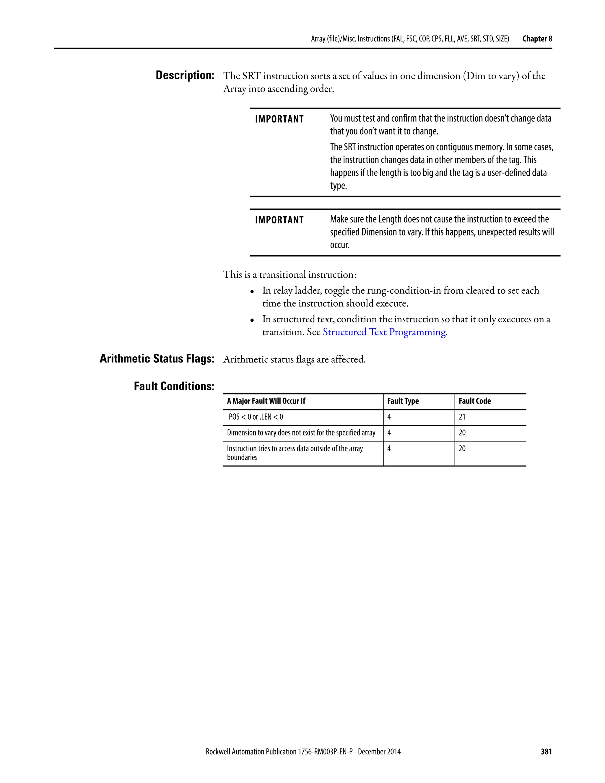
File Sort (SRT) The SRT instruction sorts a set of values in one dimension (Dim to vary) of the
Array into ascending order.
Operands:
Relay Ladder
Structured Text
The operands are the same as those for the relay ladder SRT instruction.
However, you specify the Length and Position values by accessing the .LEN and
.POS members of the CONTROL structure, rather than by including values in
the operand list.
CONTROL Structure
Operand Type Format Description
Array SINT
INT
DINT
REAL
Array tag Array to sort
Specify the first element of the group of elements to sort
Donot use CONTROL.POS in the subscript
Dimension to
vary
DINT Immediate
(0, 1, 2)
Which dimension to use
Depending on the number of dimensions, the order is:
array[dim_0,dim_1,dim_2]
array[dim_0,dim_1]
array[dim_0]
Control CONTROL Tag Control structure for the operation
Length DINT Immediate Number of elements of the array to sort
Position DINT Immediate Current element in the array
Initial valueis typically 0
SRT(Array,Dimtovary,
Control);
Mnemonic Data Type Description
.EN BOOL The enable bit indicates that the SRT instruction is enabled.
.DN BOOL The done bit is set when the specified elements have been sorted.
.ER BOOL The error bit is set when either .LEN < 0 or .POS < 0. Either of these conditions also generates a major fault.
.LEN DINT The length specifies the number of elements in the array on which the instruction
.POS DINT The position contains the position of the current element that the instruction is accessing.](https://image.slidesharecdn.com/1756-rm003-en-p-150617024022-lva1-app6892/75/1756-rm003-en-p-380-2048.jpg)

![Rockwell Automation Publication 1756-RM003P-EN-P - December 2014 383
Array (file)/Misc. Instructions (FAL, FSC, COP, CPS, FLL, AVE, SRT, STD, SIZE) Chapter 8
Example 1: Sort int _array, which is DINT[4,5].
Relay Ladder
Structured Text
control_1.LEN := 4;
control_1.POS := 0;
SRT(int_array[0,2],0,control_1);
Example 2: Sort int _array, which is DINT[4,5].
Dimension 1
Dimension 0
0 20 19 18 17 16
15 14 13 12 11
10 9 8 7 6
5 4 3 2 1
1
2
3
0 1 2 3 4
Dimension 1
Dimension 0
0 20 19 3 17 16
15 14 8 12 11
10 9 13 7 6
5 4 18 2 1
1
2
3
0 1 2 3 4
Before After
Subscripts
Subscripts
Dimension 1
Dimension 0
0 20 19 18 17 16
15 14 13 12 11
10 9 8 7 6
5 4 3 2 1
1
2
3
0 1 2 3 4
Dimension 1
Dimension 0
0 20 19 18 17 16
15 14 13 12 11
6 7 8 9 10
5 4 3 2 1
1
2
3
0 1 2 3 4
Before After
Subscripts
Subscripts](https://image.slidesharecdn.com/1756-rm003-en-p-150617024022-lva1-app6892/75/1756-rm003-en-p-383-2048.jpg)
![384 Rockwell Automation Publication 1756-RM003P-EN-P - December 2014
Chapter 8 Array (file)/Misc. Instructions (FAL, FSC, COP, CPS, FLL, AVE, SRT, STD, SIZE)
Relay Ladder
Structured Text
control_1.LEN := 5;
control_1.POS := 0;
SRT(int_array[2,0],1,control_1);](https://image.slidesharecdn.com/1756-rm003-en-p-150617024022-lva1-app6892/75/1756-rm003-en-p-384-2048.jpg)
![Rockwell Automation Publication 1756-RM003P-EN-P - December 2014 385
Array (file)/Misc. Instructions (FAL, FSC, COP, CPS, FLL, AVE, SRT, STD, SIZE) Chapter 8
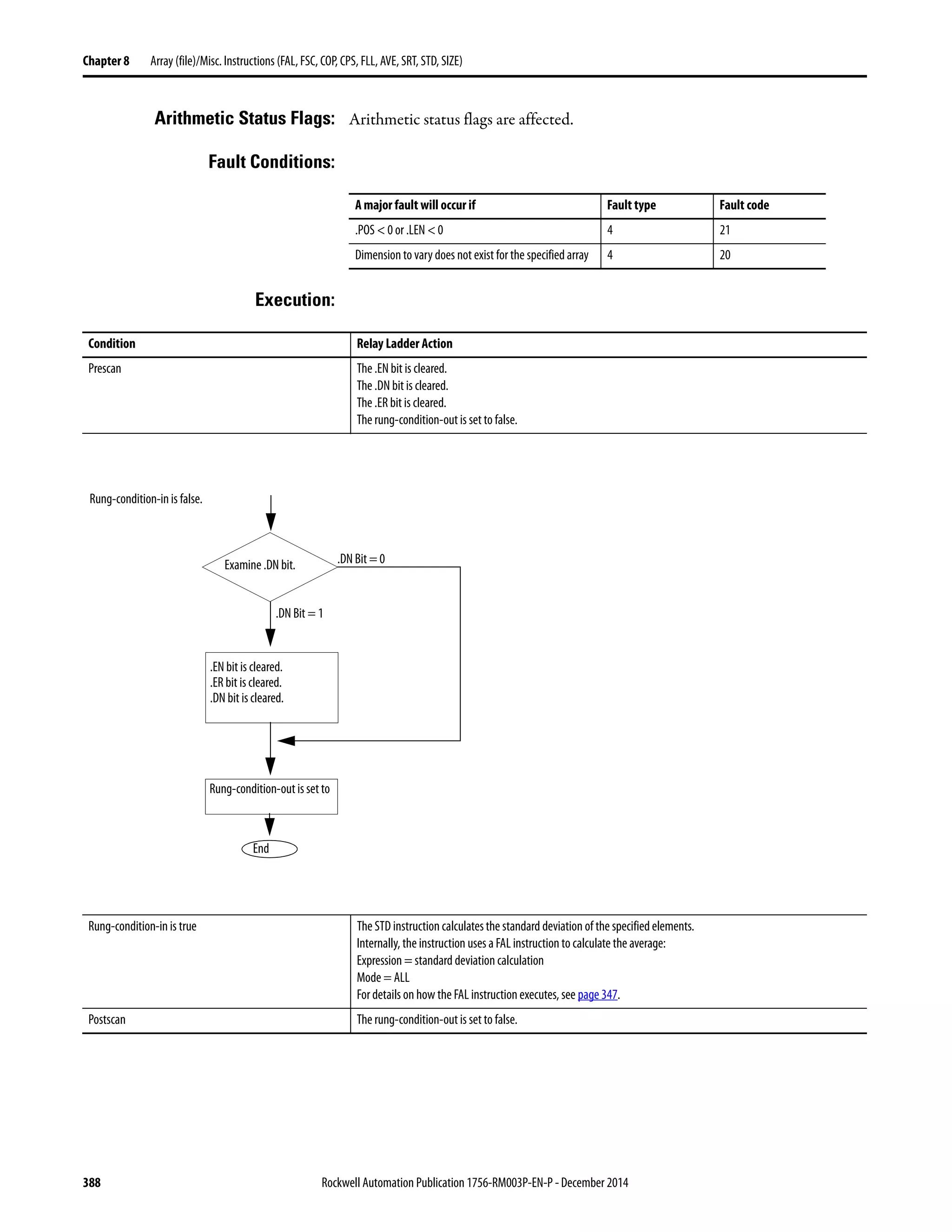
File Standard Deviation (STD) The STD instruction calculates the standard deviation of a set of values in one
dimension of the Array and stores the result in the Destination.
Operands:
Relay Ladder
CONTROL Structure
Operand Type Format Description
Array SINT
INT
DINT
REAL
Array tag Find the standard deviation of the values in this array
Specify the first element of the group of elements to use in
calculating the standard deviation
Donot use CONTROL.POS in the subscript
A SINT or INT tag converts to a DINT value by sign-extension.
Dimension to
vary
DINT Immediate
(0, 1, 2)
Which dimension to use
Depending on the number of dimensions, the order is:
array[dim_0,dim_1,dim_2]
array[dim_0,dim_1]
array[dim_0]
Destination REAL Tag Result of the operation
Control CONTROL Tag Control structure for the operation
Length DINT Immediate Number of elements of the arrayto use in calculatingthe
standard deviation
Position DINT Immediate Current element in the array
Initial valueis typically 0
Mnemonic Data Type Description
.EN BOOL The enable bit indicates that the STD instruction is enabled.
.DN BOOL The done bit is set when the calculation is complete.
.ER BOOL Theerrorbitissetwhentheinstructiongeneratesanoverflow.Theinstructionstopsexecutinguntiltheprogramclearsthe
.ER bit. The position of the element that caused the overflow is stored in the .POS value.
.LEN DINT The length specifies the number of elements in the arrayon which the instruction operates.
.POS DINT The position contains the position of the current element that the instruction is accessing.](https://image.slidesharecdn.com/1756-rm003-en-p-150617024022-lva1-app6892/75/1756-rm003-en-p-385-2048.jpg)
![386 Rockwell Automation Publication 1756-RM003P-EN-P - December 2014
Chapter 8 Array (file)/Misc. Instructions (FAL, FSC, COP, CPS, FLL, AVE, SRT, STD, SIZE)
Structured Text
Structured text does not have an STD instruction, but you can achieve the same
results by using a SIZE instruction and a FOR...DO or other loop construct.
SIZE(array,0,length);
sum := 0;
FOR position = 0 TO length-1 DO
sum := sum + array[position];
END_FOR;
average := sum / length;
sum := 0;
FOR position = 0 TO length-1 DO
sum := sum + ((array[position] - average)**2);
END_FOR;
destination := SQRT(sum /(length-1));
See Structured Text Programming for information on the syntax of constructs
within structured text.](https://image.slidesharecdn.com/1756-rm003-en-p-150617024022-lva1-app6892/75/1756-rm003-en-p-386-2048.jpg)
![Rockwell Automation Publication 1756-RM003P-EN-P - December 2014 387
Array (file)/Misc. Instructions (FAL, FSC, COP, CPS, FLL, AVE, SRT, STD, SIZE) Chapter 8
Description: The standard deviation is calculated according to this formula:
Where:
• start = dimension-to-vary subscript of the array operand
• xi = variable element in the array
• N = number of specified elements in the array
• AVE =
IMPORTANT Make sure the length does not cause the instruction to exceed the
specified dimension to vary. If this happens, the destination will be
incorrect.
X start i+( ) AVE–〈 〉
2
[ ]
i 1=
N
∑
⎝ ⎠
⎜ ⎟
⎜ ⎟
⎛ ⎞
N 1–( )
--------------------------------------------------------------------
Standard Deviation =
x start i+( )
i 1=
N
∑
⎝ ⎠
⎜ ⎟
⎜ ⎟
⎛ ⎞
N
-----------------------------------------](https://image.slidesharecdn.com/1756-rm003-en-p-150617024022-lva1-app6892/75/1756-rm003-en-p-387-2048.jpg)
![Rockwell Automation Publication 1756-RM003P-EN-P - December 2014 389
Array (file)/Misc. Instructions (FAL, FSC, COP, CPS, FLL, AVE, SRT, STD, SIZE) Chapter 8
Example 1: Calculate the standard deviation of dint_array, which is DINT[4,5].
Relay Ladder
Structured Text
SIZE(dint_array,0,length);
sum := 0;
FOR position = 0 TO (length-1) DO
sum := sum + dint_array[position];
END_FOR;
average := sum / length;
sum := 0;
FOR position = 0 TO (length-1) DO
sum := sum + ((dint_array[position] - average)**2);
END_FOR;
real_std := SQRT(sum / (length-1));
Dimension 1
Dimension 0
0 20 19 18 17 16
15 14 13 12 11
10 9 8 7 6
5 4 3 2 1
1
2
3
0 1 2 3 4
STD
16 8.5–〈 〉
2
11 8.5–〈 〉
2
6 8.5–〈 〉
2
1 8.5–〈 〉
2
+ + +
4 1–〈 〉
--------------------------------------------------------------------------------------------------------------------------- 6.454972= =
AVE
16 11 6 1+ + +
4
-------------------------------------
34
4
------ 8.5= = =
Subscripts
real_std = 6.454972](https://image.slidesharecdn.com/1756-rm003-en-p-150617024022-lva1-app6892/75/1756-rm003-en-p-389-2048.jpg)
![390 Rockwell Automation Publication 1756-RM003P-EN-P - December 2014
Chapter 8 Array (file)/Misc. Instructions (FAL, FSC, COP, CPS, FLL, AVE, SRT, STD, SIZE)
Example 2: Calculate the standard deviation of dint_array, which is DINT[4,5].
Relay Ladder
Dimension 1
Dimension 0
0 20 19 18 17 16
15 14 13 12 11
10 9 8 7 6
5 4 3 2 1
1
2
3
0 1 2 3 4
STD
20 18–〈 〉
2
19 18–〈 〉
2
18 18–〈 〉
2
17 18–〈 〉
2
16 18–〈 〉
2
+ + + +
5 1–〈 〉
------------------------------------------------------------------------------------------------------------------------------------------------------------ 1.581139= =
AVE
20 19 18 17 16+ + + +
5
-------------------------------------------------------
90
5
------ 18= = =
Subscripts
real_std = 1.581139](https://image.slidesharecdn.com/1756-rm003-en-p-150617024022-lva1-app6892/75/1756-rm003-en-p-390-2048.jpg)
![Rockwell Automation Publication 1756-RM003P-EN-P - December 2014 391
Array (file)/Misc. Instructions (FAL, FSC, COP, CPS, FLL, AVE, SRT, STD, SIZE) Chapter 8
Structured Text
SIZE(dint_array,1,length);
sum := 0;
FOR position = 0 TO (length-1) DO
sum := sum + dint_array[position];
END_FOR;
average := sum / length;
sum := 0;
FOR position = 0 TO (length-1) DO
sum := sum + ((dint_array[position] - average)**2);
END_FOR;
real_std := SQRT(sum / (length-1));](https://image.slidesharecdn.com/1756-rm003-en-p-150617024022-lva1-app6892/75/1756-rm003-en-p-391-2048.jpg)
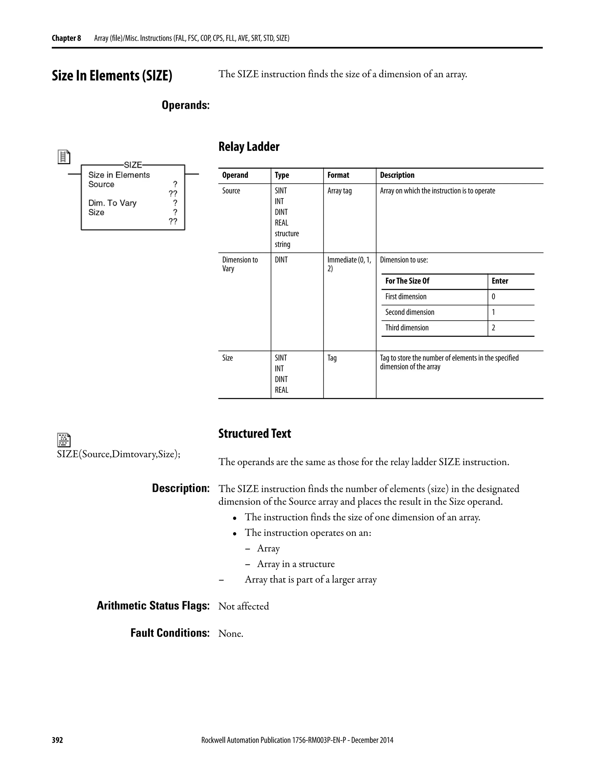
![Rockwell Automation Publication 1756-RM003P-EN-P - December 2014 393
Array (file)/Misc. Instructions (FAL, FSC, COP, CPS, FLL, AVE, SRT, STD, SIZE) Chapter 8
Execution:
Example 1: Find the number of elements in dimension 0 (first dimension) of array_a. Store
the size in array_a_size. In this example, dimension 0 of array_a has 10 elements.
Relay Ladder
Structured Text
SIZE(array_a,0,array_a_size);
Condition Relay Ladder Action Structured Text Action
Prescan The rung-condition-out is set to false. No action taken.
Rung-condition-in is false The rung-condition-out is set to false. N/A
Rung-condition-in is true The instruction executes.
The rung-condition-out is set to true.
N/A
EnableIn is set N/A EnableIn is always set.
The instruction executes.
Instruction execution The instruction finds the size of a dimension. The instruction finds the size of a dimension.
Postscan The rung-condition-out is set to false. No action taken.
Size in Elements
Source array_a[0]
255
Dim. To Vary 0
Size array_a_size
10
SIZE](https://image.slidesharecdn.com/1756-rm003-en-p-150617024022-lva1-app6892/75/1756-rm003-en-p-393-2048.jpg)
![394 Rockwell Automation Publication 1756-RM003P-EN-P - December 2014
Chapter 8 Array (file)/Misc. Instructions (FAL, FSC, COP, CPS, FLL, AVE, SRT, STD, SIZE)
Example 2: Find the number of elements in the DATA member of string_1, which is a string.
Store the size in string_1_size. In this example, the DATA member of string_1 has
82 elements. (The string uses the default STRING data type.) Since each element
holds one character, string_1 can contain up to 82 characters.
Relay Ladder
Structured Text
SIZE(string_1.DATA[0],0,string_1_size);
Size in Elements
Source string_1.DATA[0]
'$00'
Dim. To Vary 0
Size string_1_size
82
SIZE](https://image.slidesharecdn.com/1756-rm003-en-p-150617024022-lva1-app6892/75/1756-rm003-en-p-394-2048.jpg)
![Rockwell Automation Publication 1756-RM003P-EN-P - December 2014 395
Array (file)/Misc. Instructions (FAL, FSC, COP, CPS, FLL, AVE, SRT, STD, SIZE) Chapter 8
Example 3: Strings_a is an array of string structures. The SIZE instruction finds the number
of elements in the DATA member of the string structure and stores the size in
data_size_a. In this example, the DATA member has 24 elements. (The string
structure has a user-specified length of 24.)
Relay Ladder
Structured Text
SIZE(strings_a[0].DATA[0],0,data_size_a);
Size in Elements
Source strings_a[0].DATA[0]
'$00'
Dim. To Vary 0
Size data_size_a
24
SIZE](https://image.slidesharecdn.com/1756-rm003-en-p-150617024022-lva1-app6892/75/1756-rm003-en-p-395-2048.jpg)


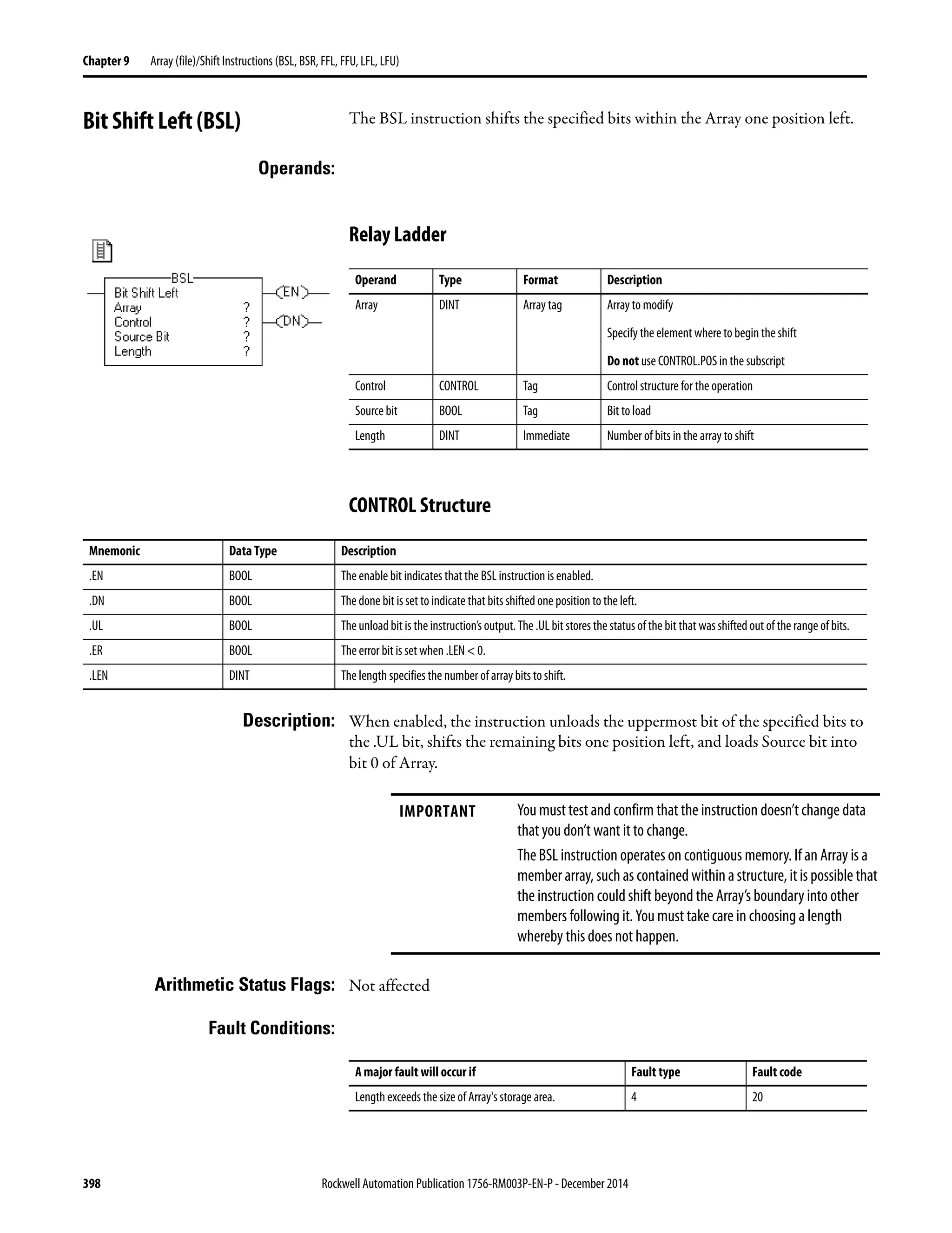

![400 Rockwell Automation Publication 1756-RM003P-EN-P - December 2014
Chapter 9 Array (file)/Shift Instructions (BSL, BSR, FFL, FFU, LFL, LFU)
Example 1: When enabled, the BSL instruction starts at bit 0 in array_dint[0]. The
instruction unloads array_dint[0].9 into the .UL bit, shifts the remaining bits,
Postscan The rung-condition-out is set to false.
Condition Relay Ladder Action
Rung-condition-in is true.
Examine .EN Bit
.EN Bit = 1
.EN Bit = 0
End
.DN bit is set.
Shift array one position to the left.
.EN bit is set.
Rung-condition-out is set to
true.
.DN bit is set.
.POS = .LEN
.LEN = 0
Yes
No
.LEN < 0
Yes
No
Source
Bit
.UL Bit Array
Examine Source Bit
.Source Bit = 1
.Source Bit = 0
.UL bit remains set.
.UL bit is set.
.ER bit is set.](https://image.slidesharecdn.com/1756-rm003-en-p-150617024022-lva1-app6892/75/1756-rm003-en-p-400-2048.jpg)
![Rockwell Automation Publication 1756-RM003P-EN-P - December 2014 401
Array(file)/Shift Instructions (BSL, BSR, FFL, FFU, LFL, LFU) Chapter 9
and loads input_1 into array_dint[0].0. The values in the remaining bits
(10…31) are invalid.
Example 2: When enabled, the BSL instruction starts at bit 0 in array_dint[0]. The
instruction unloads array_dint[1].25 into the .UL bit, shifts the remaining bits,
and loads input_1 into array_dint[0].0. The values in the remaining bits (31…26
in array_dint[1]) are invalid. Note how array_dint[0].31 shifts across words to
array_dint[1].0.
9 8 7 6 5 4 3 2 1 0
array_dint[0]
Before shift
1 1 1 1 0 0 0 0 1 1 1 1 0 0 0 0 1 1 1 1 0 0 0 0 1 1 1 1 0 0 0 0
9 8 7 6 5 4 3 2 1 0
array_dint[0]
After shift
0 1 1 1 1 0 0 0 0 1
1
input_1
0
.UL bit
These bits shift left
31 0
array_dint[0] 1 1 1 1 0 0 0 0 1 1 1 1 0 0 0 0 1 1 1 1 0 0 0 0 1 1 1 1 0 0 0 0
31 0
array_dint[1] 0 0 1 1 1 1 0 0 0 0 1 1 1 1 0 0 0 0 1 1 1 1 0 0 0 0
1
input_1
These bits shift left
0
.UL bit
These bits shift left](https://image.slidesharecdn.com/1756-rm003-en-p-150617024022-lva1-app6892/75/1756-rm003-en-p-401-2048.jpg)
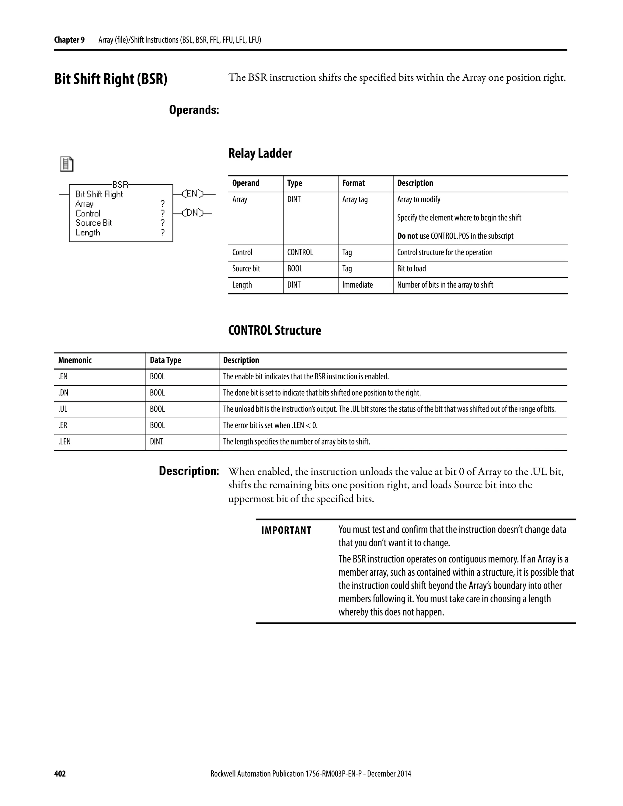
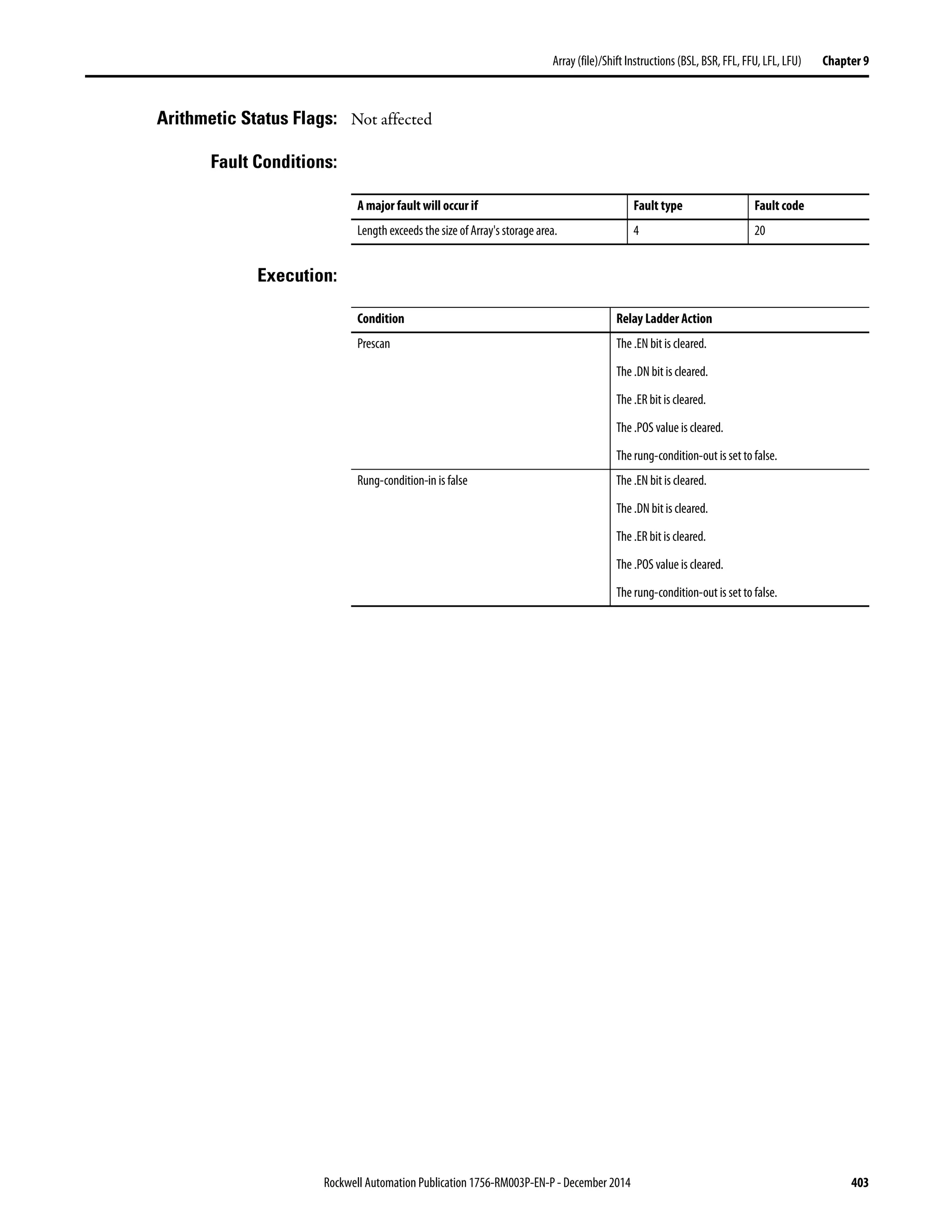

![Rockwell Automation Publication 1756-RM003P-EN-P - December 2014 405
Array(file)/Shift Instructions (BSL, BSR, FFL, FFU, LFL, LFU) Chapter 9
Example 1: When enabled, the BSR instruction starts at bit 9 in array_dint[0]. The
instruction unloads array_dint[0].0 into the .UL bit, shifts the remaining bits
right, and loads input_1 into array_dint[0].9. The values in the remaining bits
(10…31) are invalid.
Example 2: When enabled, the BSR instruction starts at bit 25 in array_dint[1]. The
instruction unloads array_dint[0].0 into the .UL bit, shifts the remaining bits
right, and loads input_1 into array_dint[1].25. The values in the remaining bits
(31…26 in dint_array[1]) are invalid. Note how array_dint[1].0 shifts across
words into array_dint[0].31.
9 8 7 6 5 4 3 2 1 0
array_dint[0]
Before shift
1 1 1 1 0 0 0 0 1 1 1 1 0 0 0 0 1 1 1 1 0 0 0 0 1 1 1 1 0 0 0 0
9 8 7 6 5 4 3 2 1 0
array_dint[0]
After shift
1 0 0 1 1 1 1 0 0 0
These bits shift right
0
.UL bit
1
input_1
31 0
array_dint[0] 1 1 1 1 0 0 0 0 1 1 1 1 0 0 0 0 1 1 1 1 0 0 0 0 1 1 1 1 0 0 0 0
31 0
array_dint[1] 0 0 1 1 1 1 0 0 0 0 1 1 1 1 0 0 0 0 1 1 1 1 0 0 0 0
These bits shift right
0
.UL bit
These bits shift right1
input_1](https://image.slidesharecdn.com/1756-rm003-en-p-150617024022-lva1-app6892/75/1756-rm003-en-p-405-2048.jpg)


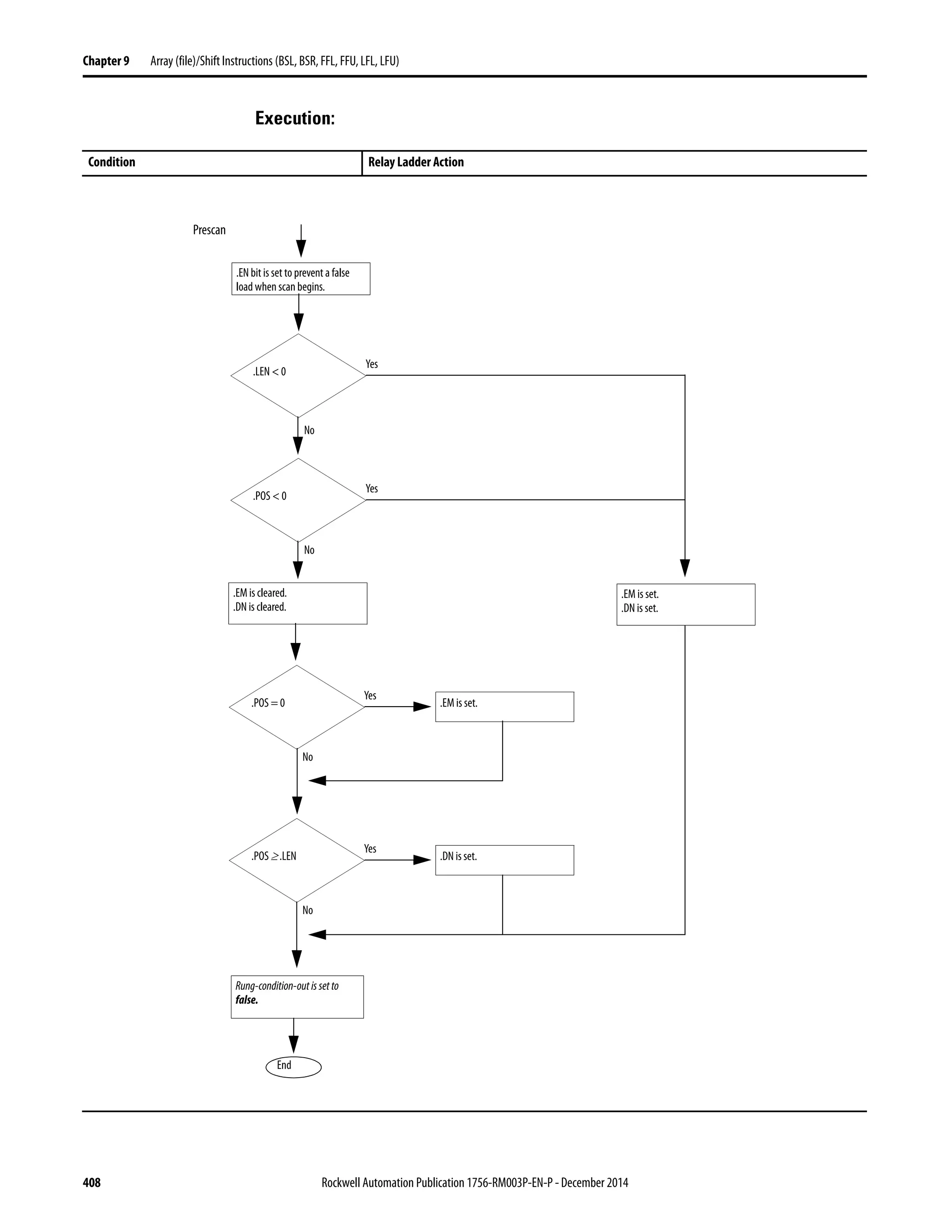

![410 Rockwell Automation Publication 1756-RM003P-EN-P - December 2014
Chapter 9 Array (file)/Shift Instructions (BSL, BSR, FFL, FFU, LFL, LFU)
Postscan The rung-condition-out is set to false.
Condition Relay Ladder Action
Rung-condition-in is true.
End
Rung-condition-out is set to
true.
Examine .EN bit.
.EN = 0
.EN = 1
.EN bit is set. .LEN < 0
Yes
No
.POS < 0
Yes
No
.EM bit is set.
.DN is set.
.EM bit is cleared.
.DN is cleared.
.POS = .POS + 1
.POS ≥ .LEN
Yes
No
.DN bit is set.
.POS or .LEN >
Size Of Array
Yes
No
Major Fault
.POS > .LEN
Yes
No
.POS = .POS - 1
FIFO[.POS - 1] = Source
.LEN < 0
Yes
No
.POS < 0
Yes
No
.EM bit is cleared.
.DN is cleared.
.POS = 0
Yes
No
.EM bit is set.
.POS ≥ .LEN
Yes
No
.DN bit is set.
.EM bit is set.
.DN is set.](https://image.slidesharecdn.com/1756-rm003-en-p-150617024022-lva1-app6892/75/1756-rm003-en-p-410-2048.jpg)
![Rockwell Automation Publication 1756-RM003P-EN-P - December 2014 411
Array(file)/Shift Instructions (BSL, BSR, FFL, FFU, LFL, LFU) Chapter 9
Example: When enabled, the FFL instruction loads value_1 into the next position in the
FIFO, which is array_dint[5] in this example.
BeforeFIFOload AfterFIFOload
array_dint[0] 00000 00000
11111 11111
22222 22222
33333 control_1.pos=5 33333
44444 value_1= 55555 44444
array_dint[5] 00000 55555
00000 00000 control_1.pos=6
00000 00000
00000 00000
00000 00000](https://image.slidesharecdn.com/1756-rm003-en-p-150617024022-lva1-app6892/75/1756-rm003-en-p-411-2048.jpg)


![416 Rockwell Automation Publication 1756-RM003P-EN-P - December 2014
Chapter 9 Array (file)/Shift Instructions (BSL, BSR, FFL, FFU, LFL, LFU)
Postscan The rung-condition-out is set to false.
Condition Relay Ladder Action
Rung-condition-in is true.
End
Examine .EU bit.
.EU = 0
.EU = 1
.EU bit is set. .LEN < 0
Yes
No
.POS < 0
Yes
No
.EM bit is set..EM bit is cleared.
.DN is cleared.
.LEN > Size
Of Array
Yes
No
Major Fault
.POS ≤ 1
Yes
No
.EM bit is set.
.LEN < 0 Yes
No
.POS < 0
Yes
No
.EM bit is cleared.
.DN is cleared.
.POS = 0
Yes
No
.EM bit is set.
.POS ≥ .LEN
Yes
No
.DN bit is set.
.EM bit is set.
.DN is set.
.POS < 1
Yes
No
Destination = 0
.POS = .POS -1
Destination = FIFO[0]
FIFO[i - 1] = FIFO[i]
i = i +1
i < .LEN
Yes
No
Rung-condition-outissetto
true.](https://image.slidesharecdn.com/1756-rm003-en-p-150617024022-lva1-app6892/75/1756-rm003-en-p-416-2048.jpg)
![Rockwell Automation Publication 1756-RM003P-EN-P - December 2014 417
Array(file)/Shift Instructions (BSL, BSR, FFL, FFU, LFL, LFU) Chapter 9
Example: When enabled, the FFU instruction unloads array_dint[0] into value_2 and
shifts the remaining elements in array_dint.
BeforeFIFOunload AfterFIFOunload
array_dint[0] 00000 11111
11111 22222
22222 33333
33333 44444
44444 55555
array_dint[5] 55555 00000 control_1.pos=5
00000 control_1.pos=6 00000 value_2=00000
00000 00000
00000 00000
00000 00000](https://image.slidesharecdn.com/1756-rm003-en-p-150617024022-lva1-app6892/75/1756-rm003-en-p-417-2048.jpg)


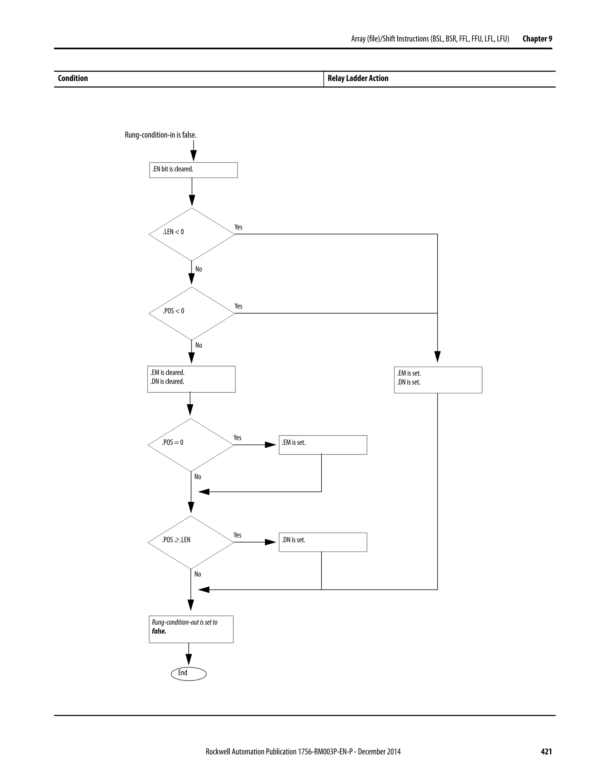
![422 Rockwell Automation Publication 1756-RM003P-EN-P - December 2014
Chapter 9 Array (file)/Shift Instructions (BSL, BSR, FFL, FFU, LFL, LFU)
Condition Relay Ladder Action
Rung-condition-in is true.
End
Rung-condition-out isset to
true.
Examine .EN bit.
.EN = 0
.EN = 1
.EN bit is set. .LEN < 0
Yes
No
.POS < 0
Yes
No
.EM bit is set.
.DN is set.
.EM bit is cleared.
.DN is cleared.
.POS = .POS + 1
.POS ≥ .LEN
Yes
No
.DN bit is set.
.POS or .LEN >
Size Of Array
Yes
No
Major Fault
.POS > .LEN
Yes
No
.POS = .POS - 1
FIFO[.POS - 1] = Source
.LEN < 0
Yes
No
.POS < 0 Yes
No
.EM bit is cleared.
.DN is cleared.
.POS = 0
Yes
No
.EM bit is set.
.POS ≥ .LEN
Yes
No
.DN bit is set.
.EM bit is set.
.DN is set.](https://image.slidesharecdn.com/1756-rm003-en-p-150617024022-lva1-app6892/75/1756-rm003-en-p-422-2048.jpg)
![Rockwell Automation Publication 1756-RM003P-EN-P - December 2014 423
Array(file)/Shift Instructions (BSL, BSR, FFL, FFU, LFL, LFU) Chapter 9
Example: When enabled, the LFL instruction loads value_1 into the next position in the
LIFO, which is array_dint[5] in this example.
BeforeLIFO load AfterLIFO load
array_dint[0] 00000 00000
11111 11111
22222 22222
33333 control_1.pos=5 33333
44444 value_1= 55555 44444
array_dint[5] 00000 55555
00000 00000 control_1.pos=6
00000 00000
00000 00000
00000 00000](https://image.slidesharecdn.com/1756-rm003-en-p-150617024022-lva1-app6892/75/1756-rm003-en-p-423-2048.jpg)


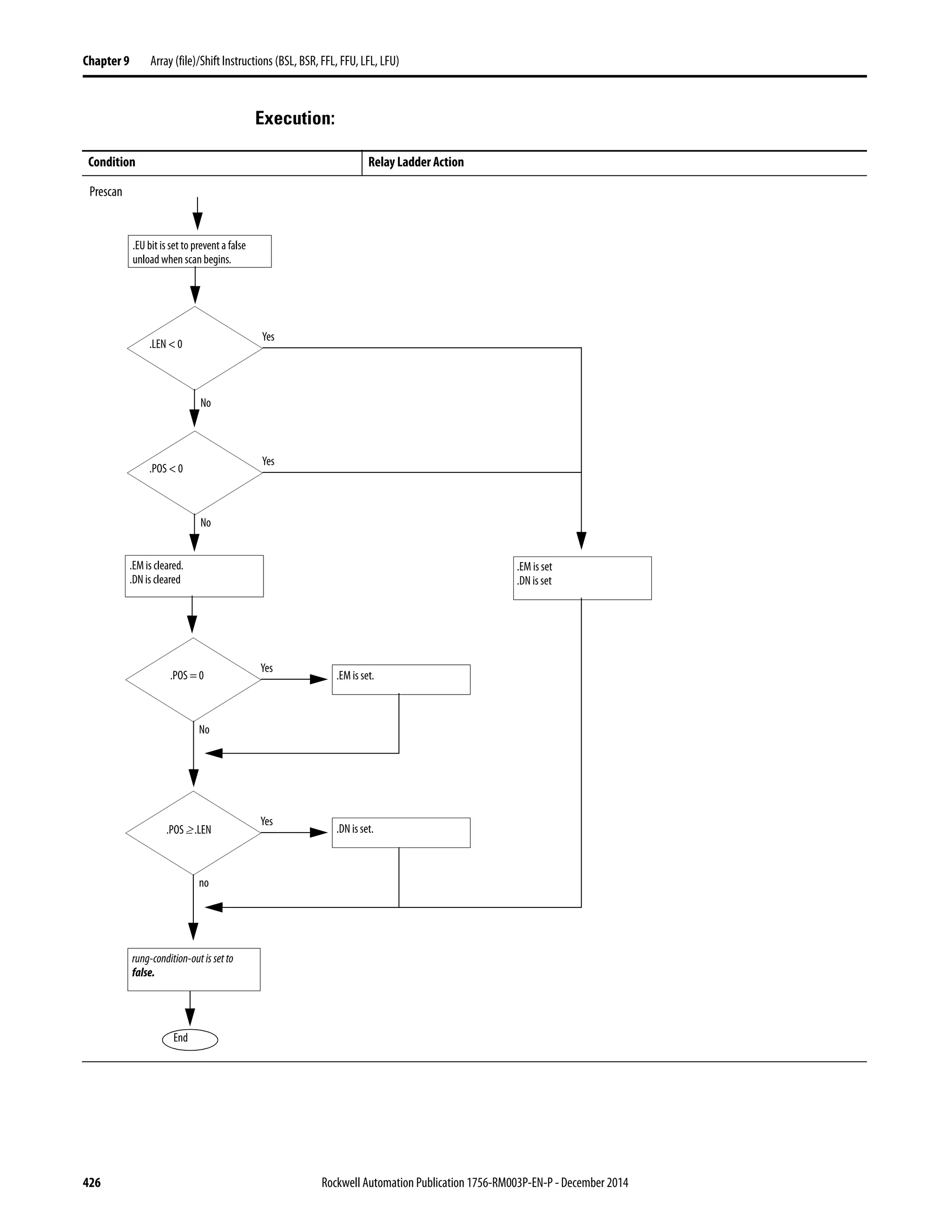
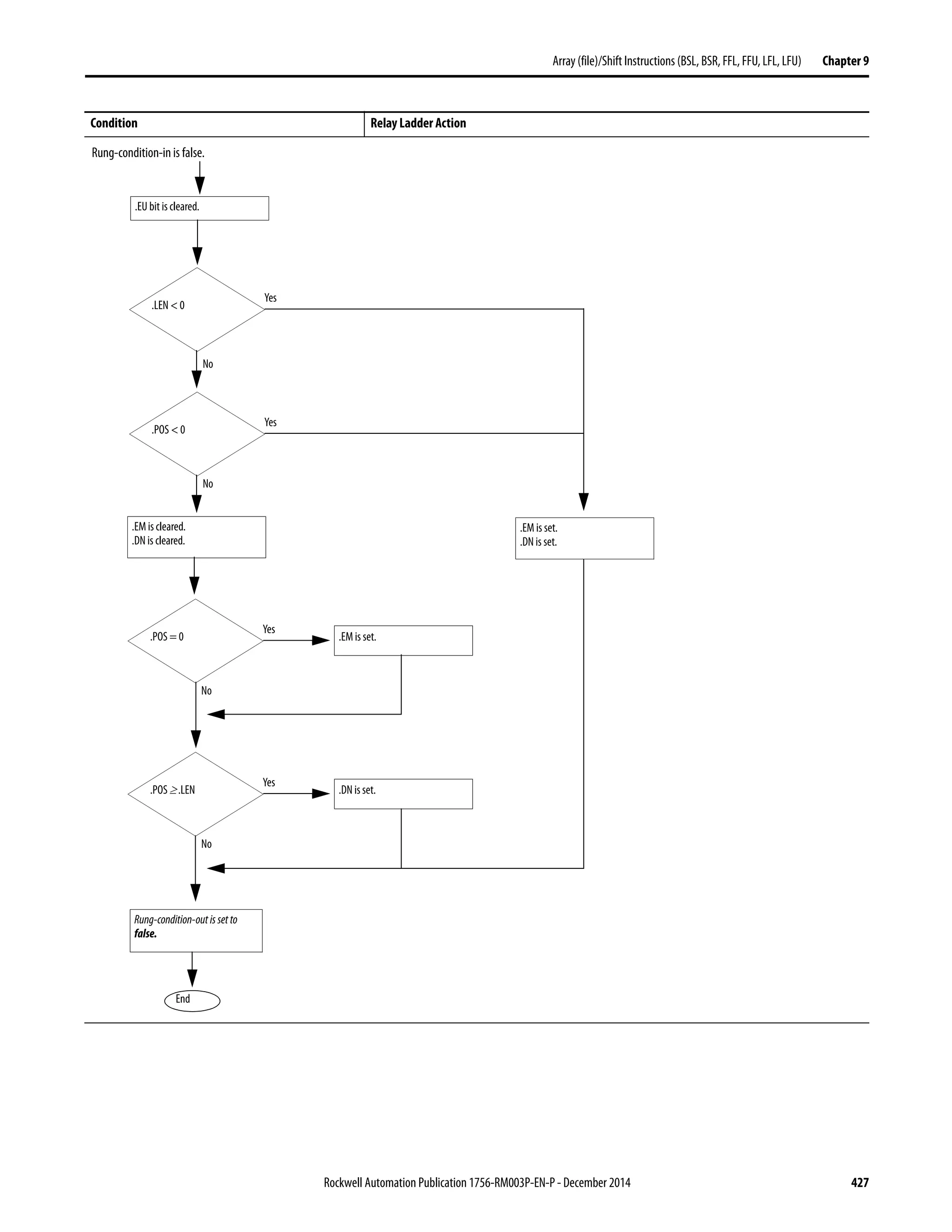
![428 Rockwell Automation Publication 1756-RM003P-EN-P - December 2014
Chapter 9 Array (file)/Shift Instructions (BSL, BSR, FFL, FFU, LFL, LFU)
Postscan The rung-condition-out is set to false.
Condition Relay Ladder Action
Rung-condition-in is true.
End
Rung-condition-outisset to
true.
Examine .EU bit.
.EU = 0
.EU = 1
.EU bit is set. .LEN < 0
Yes
No
.POS < 0
Yes
No
.EM bit is set.
.DN is set.
.EM bit is cleared.
.DN is cleared.
.LEN > Size Of
Array
Yes
No
Major Fault
.POS ≤ 1
Yes
No
.EM bit is set.
.LEN < 0
Yes
No
.POS < 0
Yes
No
.EM bit is cleared
.DN is cleared
.POS = 0
Yes
No
.EM bit is set.
.POS ≥ .LEN
Yes
No
.DN bit is set.
.EM bit is set.
.DN is set.
.POS < 1
Yes
No
.POS > .LEN
Yes
No
.POS = .LEN
Destination = 0
Destination = LIFO[control.POS]
LIFO[control.POS) = 0
.POS = .POS -1](https://image.slidesharecdn.com/1756-rm003-en-p-150617024022-lva1-app6892/75/1756-rm003-en-p-428-2048.jpg)
![Rockwell Automation Publication 1756-RM003P-EN-P - December 2014 429
Array(file)/Shift Instructions (BSL, BSR, FFL, FFU, LFL, LFU) Chapter 9
Example: When enabled, the LFU instruction unloads array_dint[5] into value_2.
BeforeLIFO unload AfterLIFO unload
array_dint[0] 00000 00000
11111 11111
22222 22222
33333 33333
44444 44444
array_dint[5] 55555 00000 control_1.pos=5
00000 control_1.pos=6 00000 value_2=55555
00000 00000
00000 00000
00000 00000](https://image.slidesharecdn.com/1756-rm003-en-p-150617024022-lva1-app6892/75/1756-rm003-en-p-429-2048.jpg)


![434 Rockwell Automation Publication 1756-RM003P-EN-P - December 2014
Chapter 10 Sequencer Instructions (SQI, SQO, SQL)
Execution:
Condition: Relay Ladder Action
Prescan The rung-condition-out is set to false.
Rung-condition-in is false The rung-condition-out is set to false.
Postscan The rung-condition-out is set to false.
.LEN≤ 0 .POS < 0
or
.POS > .LEN
Masked Source =
MaskedArray[.POS]
Yes
Rung-condition-in is true.
No
End
.ER bit is set.
Rung-condition-out is set to false.
yes
.ER bit is cleared.
No
Rung-condition-out is set to true.](https://image.slidesharecdn.com/1756-rm003-en-p-150617024022-lva1-app6892/75/1756-rm003-en-p-434-2048.jpg)

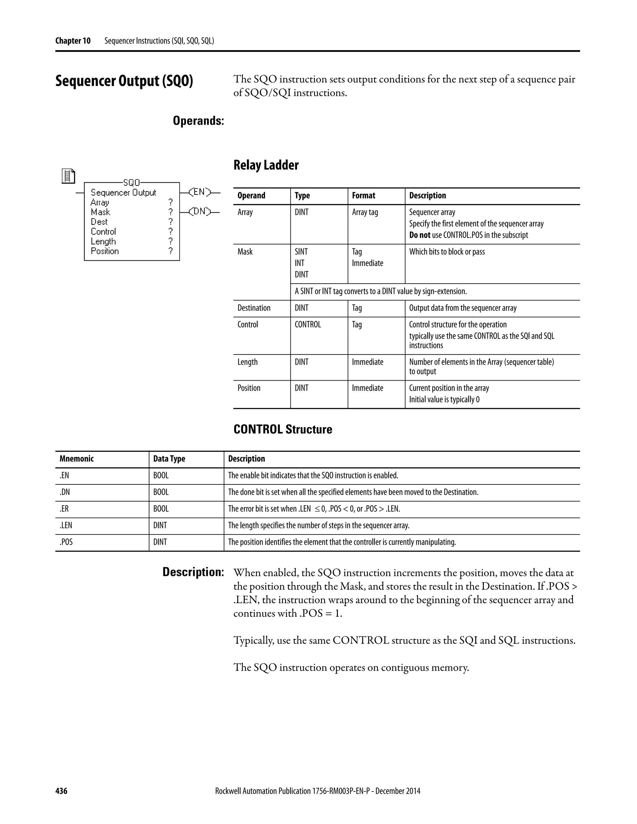

![438 Rockwell Automation Publication 1756-RM003P-EN-P - December 2014
Chapter 10 Sequencer Instructions (SQI, SQO, SQL)
Execution:
Condition Relay Ladder Action
Prescan The .EN bit is set to prevent a false load when the program scan begins.
The rung-condition-out is set to false.
Rung-condition-in is false The .EN bit is cleared.
The rung-condition-out is set to false.
Postscan The rung-condition-out is set to false.
Rung-condition-in is true.
.LEN ≤ 0 or
.POS < 0
No
Yes
.DN bit is set.
.POS = .LEN
No
Yes
Examine .EN
bit.
.EN = 0
.EN = 1
.EN bit is set.
.ER bit is cleared.
.DN bit is set.
.POS ≥ .LEN
Yes
No
.POS = .POS + 1
.POS Value
rolls over
Yes
No
.ER bit is set.
Rung-condition-out is
set to true.
.DN bit is set..POS = .LEN Yes
No
Destination=(DestinationAND(NOT(Mask)))OR
(Array[control.POS] AND Mask)
.POS > .LEN No
Yes
.POS = 1
Goto
Error
Error](https://image.slidesharecdn.com/1756-rm003-en-p-150617024022-lva1-app6892/75/1756-rm003-en-p-438-2048.jpg)
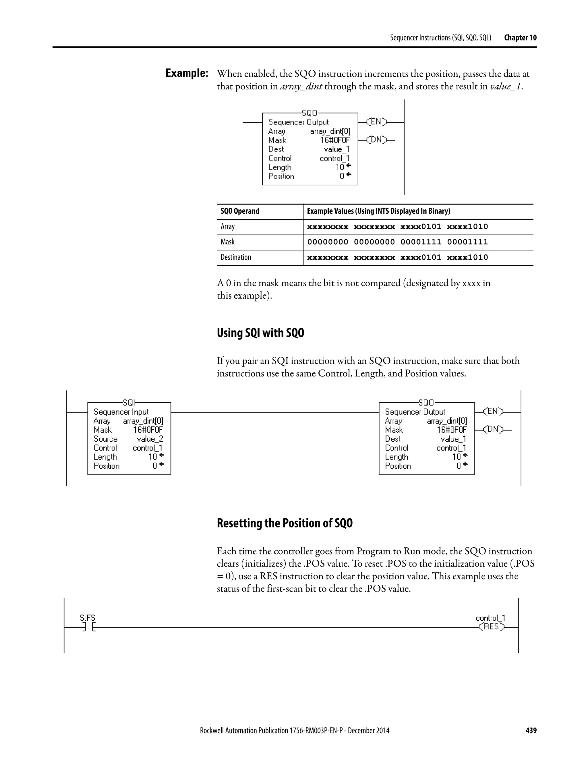
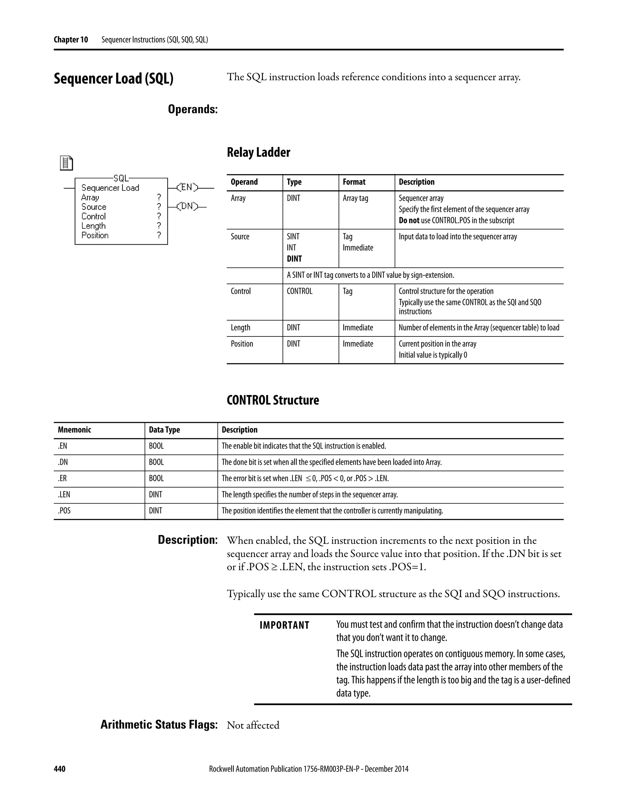

![442 Rockwell Automation Publication 1756-RM003P-EN-P - December 2014
Chapter 10 Sequencer Instructions (SQI, SQO, SQL)
Postscan The rung-condition-out is set to false.
Condition Relay Ladder Action
Rung-condition-in is true.
.LEN ≤ 0 or
.POS < 0
No
Yes
.DN bit is set.
.POS = .LEN
No
Yes
examine .EN bit
.EN = 0
.EN = 1
.EN bit is set.
.ER bit is cleared.
.DN bit is set.
.POS ≥ .LEN
Yes
No
.POS = .POS + 1
.POS Value
Rolls Over
Yes
No
.ER bit is set.
end
Rung-condition-out is set to
true.
.DN bit is set..POS = .LEN
Yes
No
.POS > .LEN
No
Yes
.POS = 1
Goto
Error
Error
.LEN > size of
array
Yes
No
Array[control.POS] = Source
Major Fault](https://image.slidesharecdn.com/1756-rm003-en-p-150617024022-lva1-app6892/75/1756-rm003-en-p-442-2048.jpg)
![Rockwell Automation Publication 1756-RM003P-EN-P - December 2014 443
Sequencer Instructions (SQI, SQO, SQL) Chapter 10
Example: When enabled, the SQL instruction loads value_3 into the next position in the
sequencer array, which is array_dint[5] in this example.
Before load After load
array_dint[0] 00000 00000
11111 11111
22222 22222
33333 control_1.pos= 5 33333
44444 value_3 = 55555 44444
array_dint[5] 00000 55555
00000 00000 control_1.pos= 6
00000 00000
00000 00000
00000 00000](https://image.slidesharecdn.com/1756-rm003-en-p-150617024022-lva1-app6892/75/1756-rm003-en-p-443-2048.jpg)

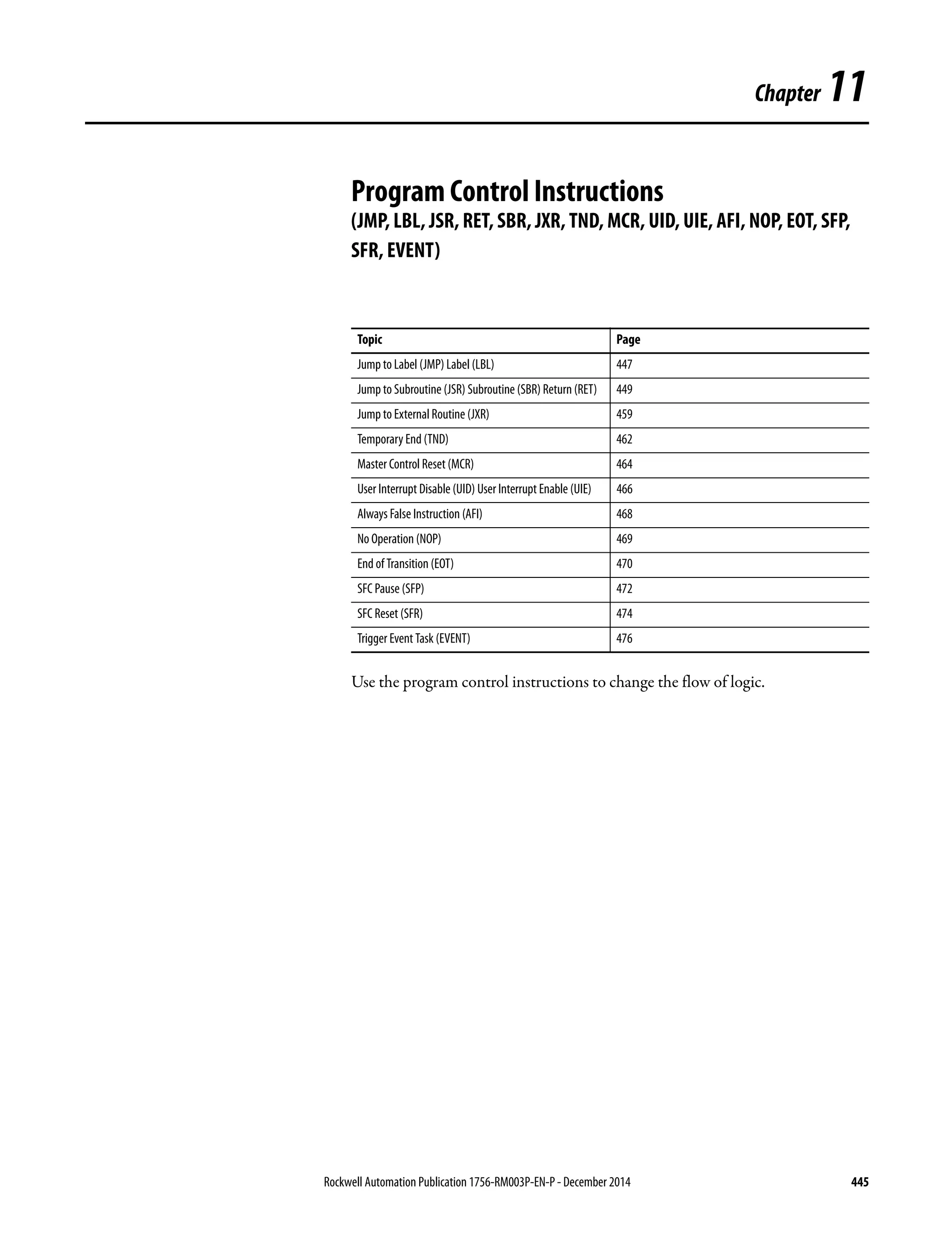


![448 Rockwell Automation Publication 1756-RM003P-EN-P - December 2014
Chapter 11 Program Control Instructions (JMP, LBL, JSR, RET, SBR, JXR, TND, MCR, UID, UIE, AFI, NOP, EOT, SFP, SFR, EVENT)
Execution:
Example: When the JMP instruction is enabled, execution jumps over successive rungs of
logic until it reaches the rung that contains the LBL instruction
with label_20.
Condition: Relay Ladder Action
Prescan The rung-condition-out is set to false.
Rung-condition-in is false The rung-condition-out is set to false.
Rung-condition-in is true The rung-condition-out is set to true.
Execution jumps to the rung that contains theLBL instruction with the referenced label name.
Postscan The rung-condition-out is set to false.
[Other Rungs of Code]](https://image.slidesharecdn.com/1756-rm003-en-p-150617024022-lva1-app6892/75/1756-rm003-en-p-448-2048.jpg)


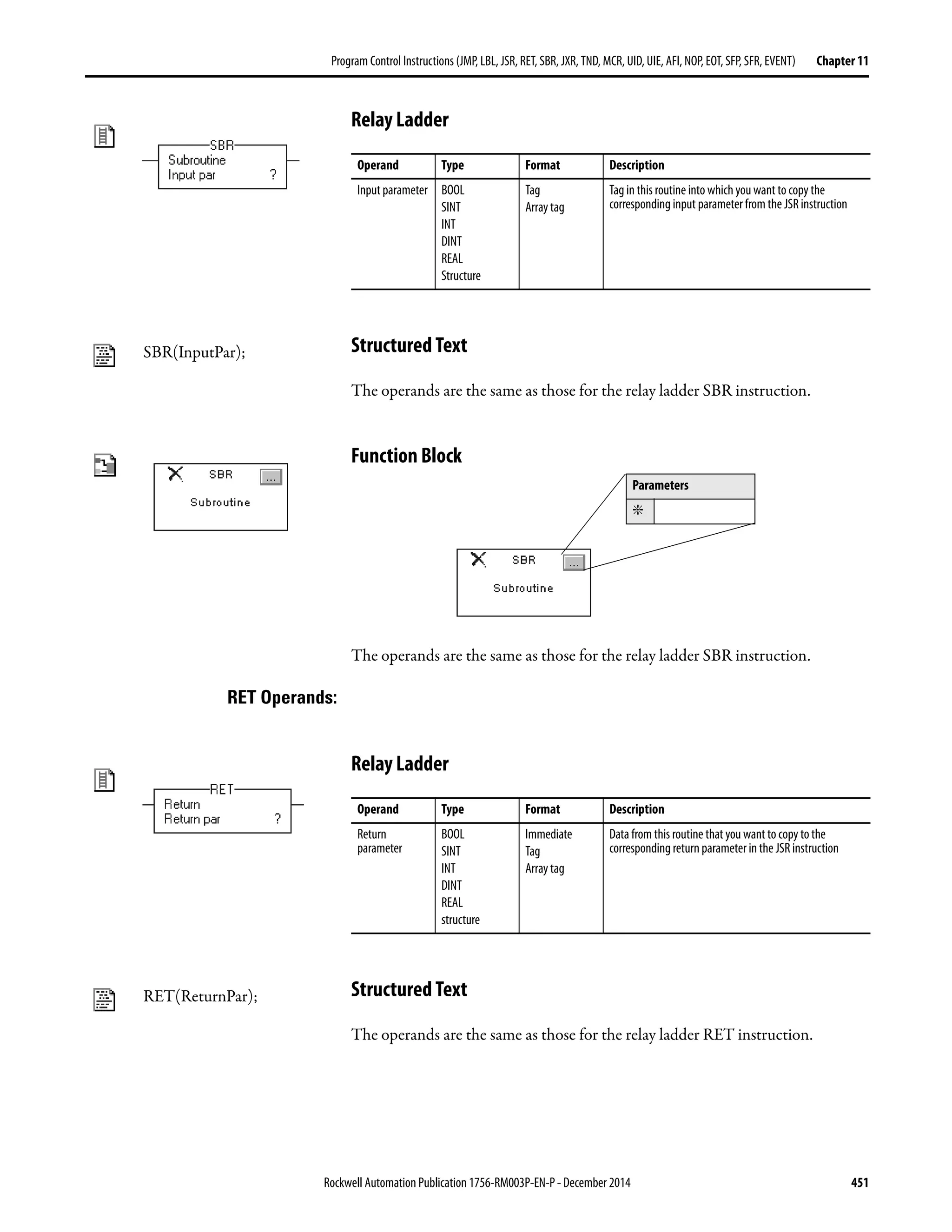


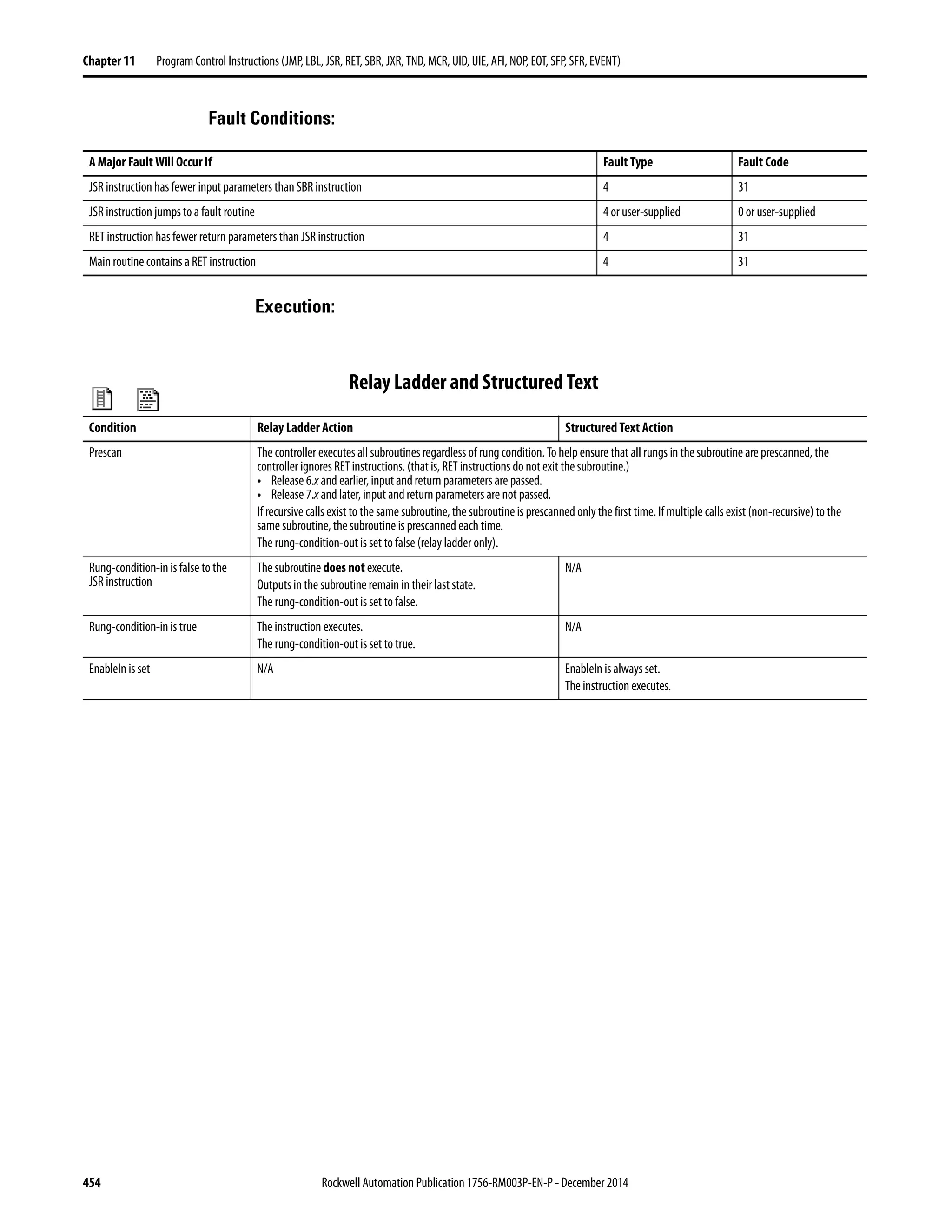

![456 Rockwell Automation Publication 1756-RM003P-EN-P - December 2014
Chapter 11 Program Control Instructions (JMP, LBL, JSR, RET, SBR, JXR, TND, MCR, UID, UIE, AFI, NOP, EOT, SFP, SFR, EVENT)
Example 1: The JSR instruction passes value_1 and value_2 to routine_1.
The SBR instruction receives value_1 and value_2 from the JSR instruction and
copies those values to value_a and value_b, respectively. Logic execution
continues in this routine.
The RET instruction sends float_a to the JSR instruction. The JSR instruction
receives float_a and copies the value to float_value_1. Logic execution continues
with the next instruction following the JSR instruction.
Relay Ladder
Structured Text
Routine Program
Main routine
Subroutine
[Otherrungsofcode]
Routine Program
Main routine JSR(routine_1,2,value_1,value_2,float_value_1);
Subroutine SBR(value_a,value_b);
<statements>;
RET(float_a);](https://image.slidesharecdn.com/1756-rm003-en-p-150617024022-lva1-app6892/75/1756-rm003-en-p-456-2048.jpg)

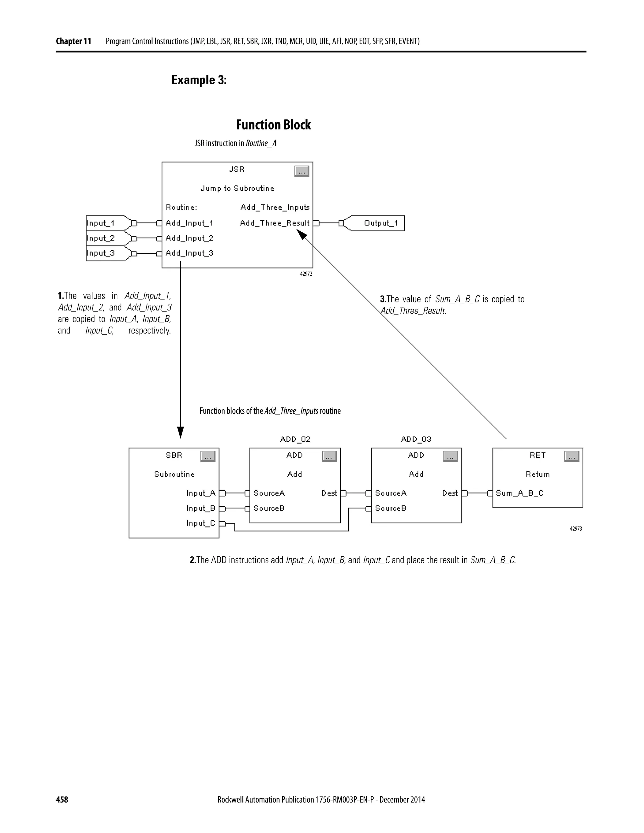

![460 Rockwell Automation Publication 1756-RM003P-EN-P - December 2014
Chapter 11 Program Control Instructions (JMP, LBL, JSR, RET, SBR, JXR, TND, MCR, UID, UIE, AFI, NOP, EOT, SFP, SFR, EVENT)
EXT_ROUTINE_CONTROL Structure
Description: Use the Jump to External Routine (JXR) instruction to call the external routine
from a ladder routine in your project. The JXR instruction supports multiple
parameters so you can pass values between the ladder routine and the external
routine.
The JXR instruction is similar to the Jump to Subroutine (JSR) instruction. The
JXR instruction initiates the execution of the specified external routine:
• The external routine executes one time.
• After the external routine executes, logic execution returns to the routine
that contains the JXR instruction.
Arithmetic Status Flags: Arithmetic status flags are not affected.
Mnemonic Data Type Description Implementation
ErrorCode SINT Ifanerroroccurs,thisvalueidentifiestheerror.Validvaluesare
from 0-255.
There are no predefined error codes. The developer of the
external routine must provide the error codes.
NumParams SINT This valueindicates thenumber of parameters associated with
this instruction.
Display only - this information is derived from the
instruction entry.
ParameterDefs EXT_ROUTINE_
PARAMETERS[10]
This array contains definitions of the parameters to pass to the
external routine. Theinstruction can pass as many as 10
parameters.
Display only - this information is derived from the
instruction entry.
ReturnParamDef EXT_ROUTIN_
PARAMETERS
This value contains definitions of the return parameter from
the external routine. There is only one return parameter.
Display only - this information is derived from the
instruction entry.
EN BOOL When set, the enable bit indicates that the JXR instruction is
enabled.
The external routine sets this bit.
ReturnsValue BOOL Ifset,thisbitindicatesthatareturnparameterwasenteredfor
the instruction. If cleared, this bit indicates that no return
parameter was entered for the instruction.
Display only - this information is derived from the
instruction entry.
DN BOOL The done bit is set when theexternal routine has executed
once to completion.
The external routine sets this bit.
ER BOOL The error bit is set if an error occurs. The instruction stops
executing until the program clears the error bit.
The external routine sets this bit.
FirstScan BOOL This bit identifies whether this is the first scan after switching
the controller to Run mode. Use FirstScan to initialize the
external routine, if needed.
The controller sets this bit to reflect scan status.
EnableOut BOOL Enable output. The external routine sets this bit.
EnableIn BOOL Enable input. The controller sets this bit to reflect rung-condition-in. The
instruction executes regardless of rung condition. The
developer of the external routineshould monitorthis status
andact accordingly.
User1 BOOL These bits are available for the user. The controller does not
initialize these bits.
Eithertheexternalroutineortheuserprogramcansetthese
bits.
User0 BOOL
ScanType1 BOOL These bits identify the current scan type:
Bit Values: Scan Type:
00 Normal
01 Pre Scan
10 Post Scan (not applicable to relay ladder
programs)
The controller sets these bits to reflect scan status.
ScanType0 BOOL](https://image.slidesharecdn.com/1756-rm003-en-p-150617024022-lva1-app6892/75/1756-rm003-en-p-460-2048.jpg)


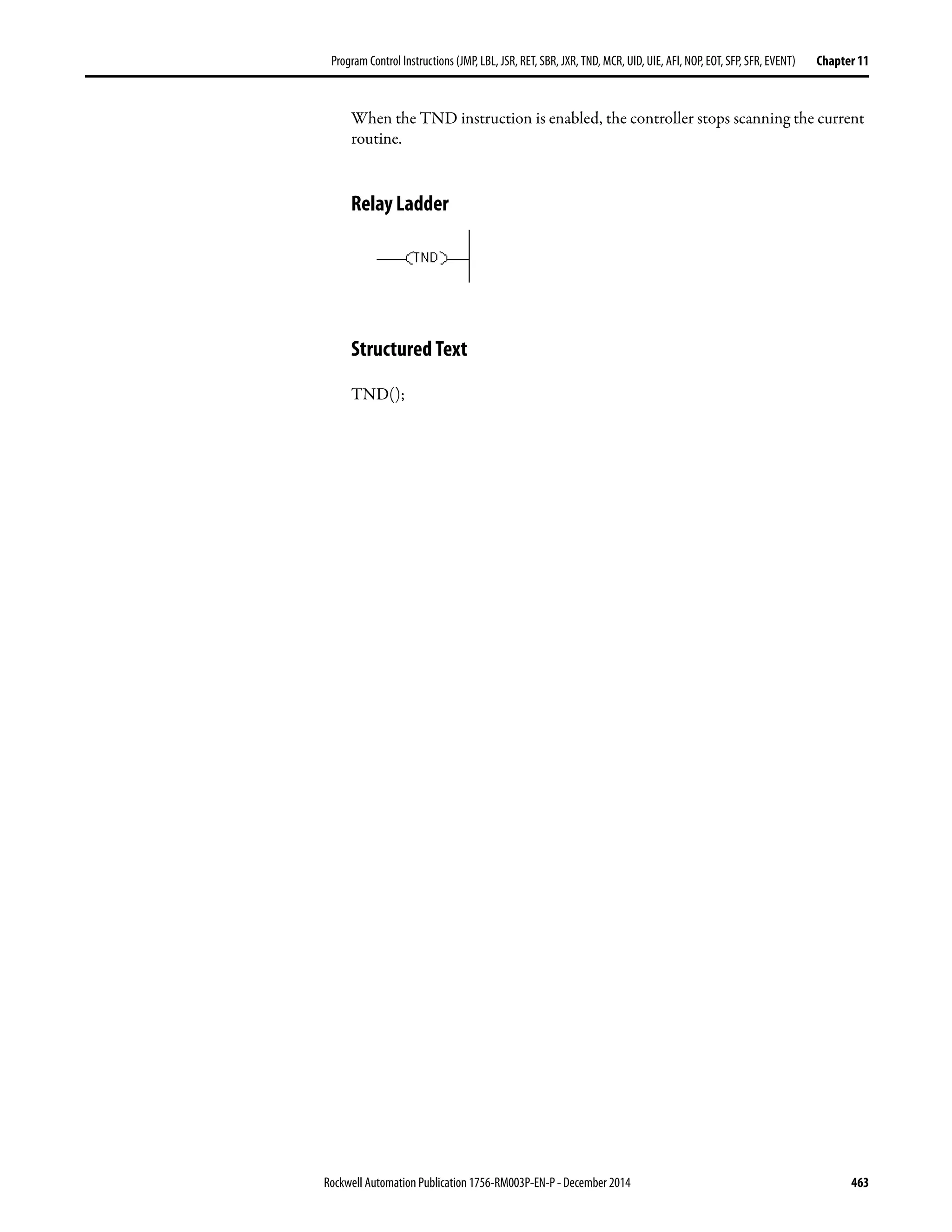


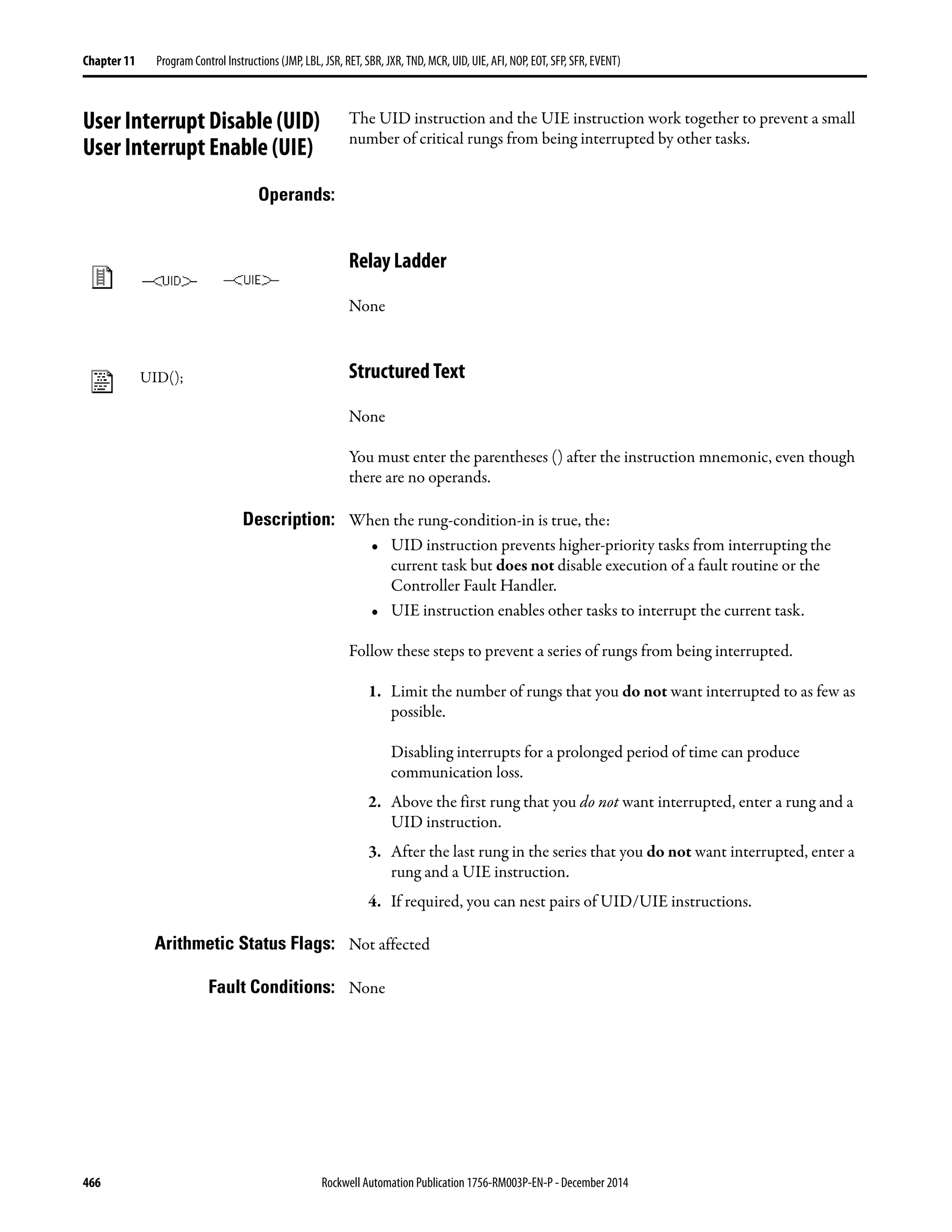
![Rockwell Automation Publication 1756-RM003P-EN-P - December 2014 467
Program Control Instructions (JMP, LBL, JSR, RET, SBR, JXR, TND, MCR, UID, UIE, AFI, NOP, EOT, SFP, SFR, EVENT) Chapter 11
Execution:
Example: When an error occurs (error_bit is on), the FSC instruction checks the error code
against a list of critical errors. If the FSC instruction finds that the error is critical
(error_check.FD is on), an alarm is annunciated. The UID and UIE instructions
prevent any other tasks from interrupting the error checking and alarming.
Relay Ladder
Structured Text
UID();
<statements>
UIE();
Condition Relay Ladder Action Structured Text Action
Prescan The rung-condition-out is set to false. No action taken.
Rung-condition-in is false The rung-condition-out is set to false. N/A
Rung-condition-in is true The instruction executes.
The rung-condition-out is set to true.
N/A
EnableIn is set N/A EnableIn is always set.
The instruction executes.
Instruction execution The UID instruction prevents interruption by higher-priority tasks.
The UIE instruction enables interruption by higher-priority tasks.
Postscan The rung-condition-out is set to false. No action taken.
UID
error_bit
EN
DN
ER
File Search/Compare
Control error_check
Length 10
Position 8
Mode ALL
Expression error_code=error_list[error_check.POS]
FSC
error_check.FD alarm
UIE](https://image.slidesharecdn.com/1756-rm003-en-p-150617024022-lva1-app6892/75/1756-rm003-en-p-467-2048.jpg)


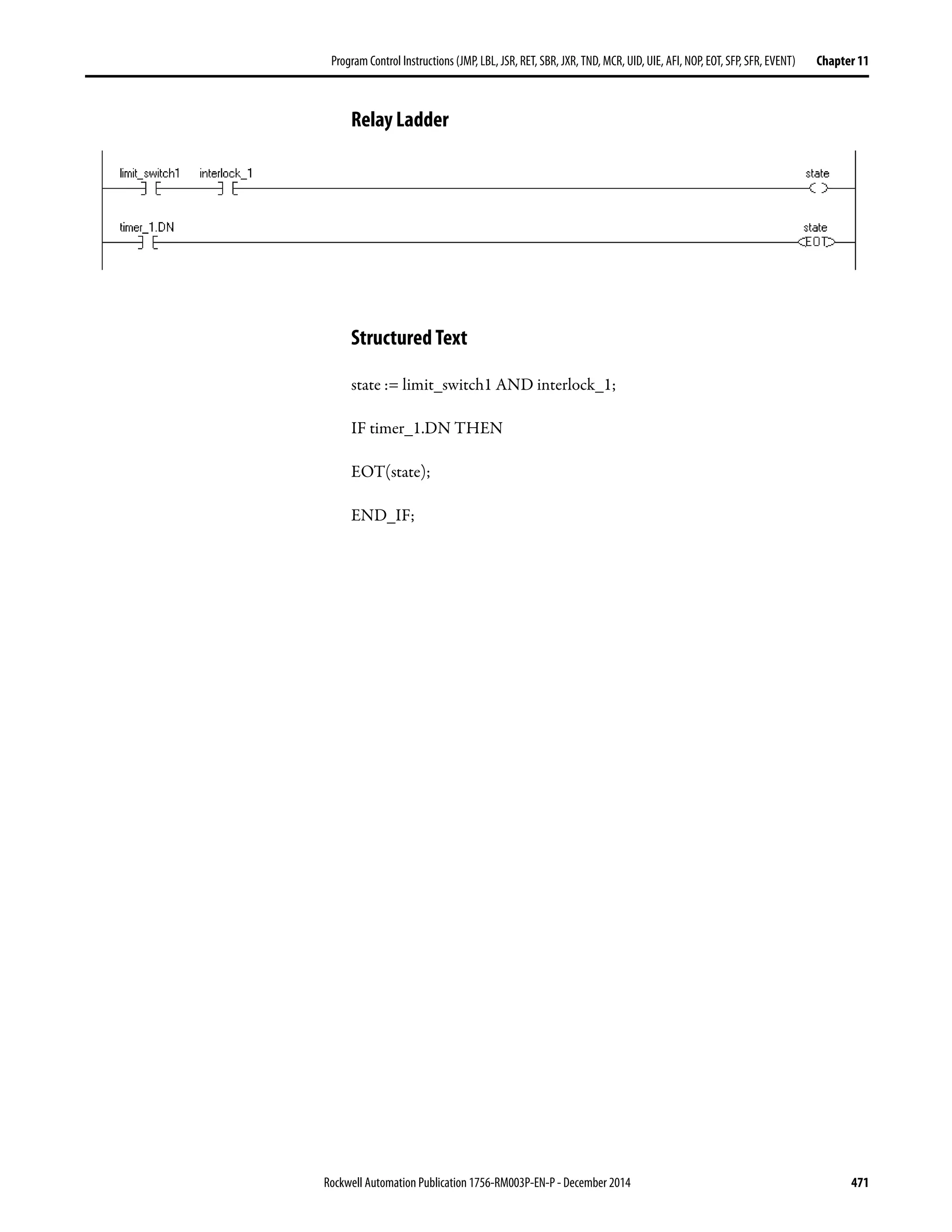

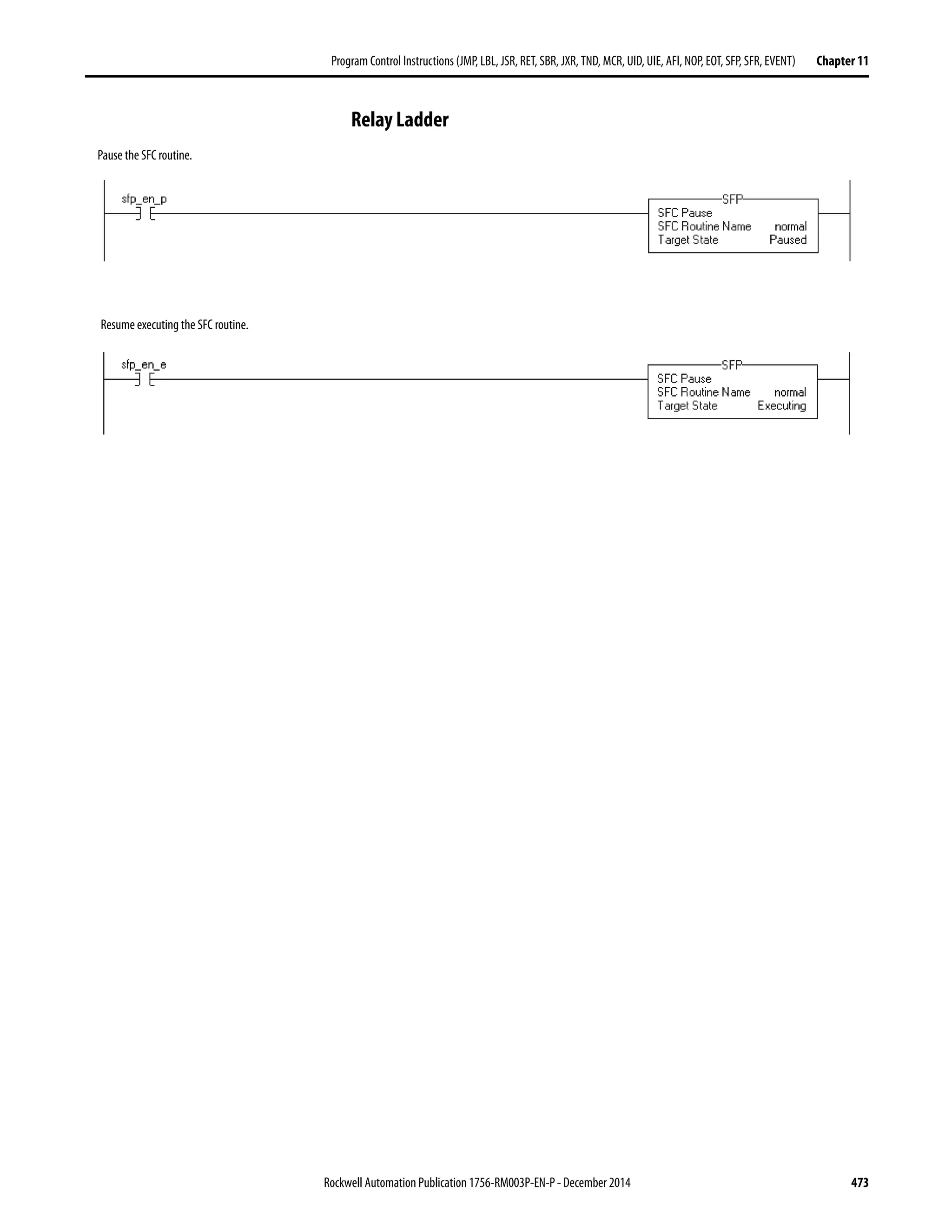
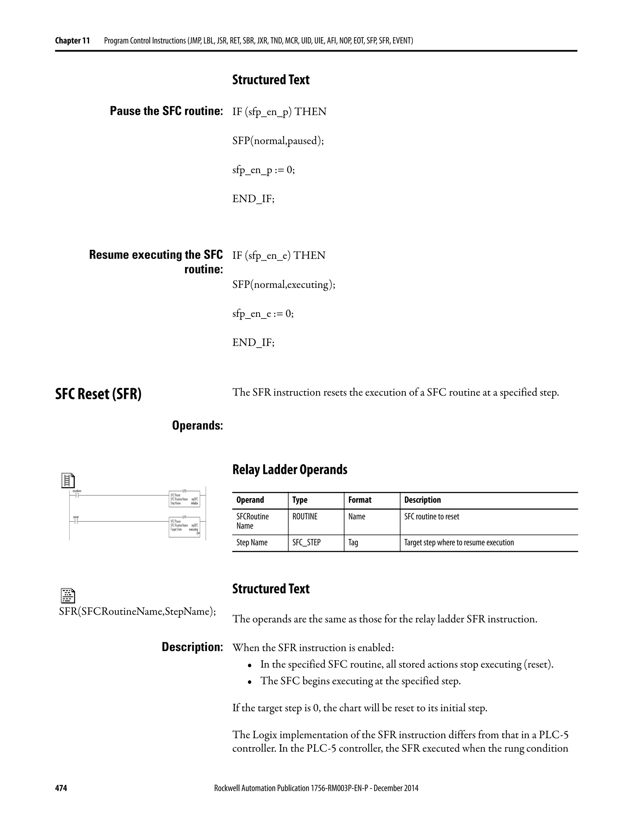


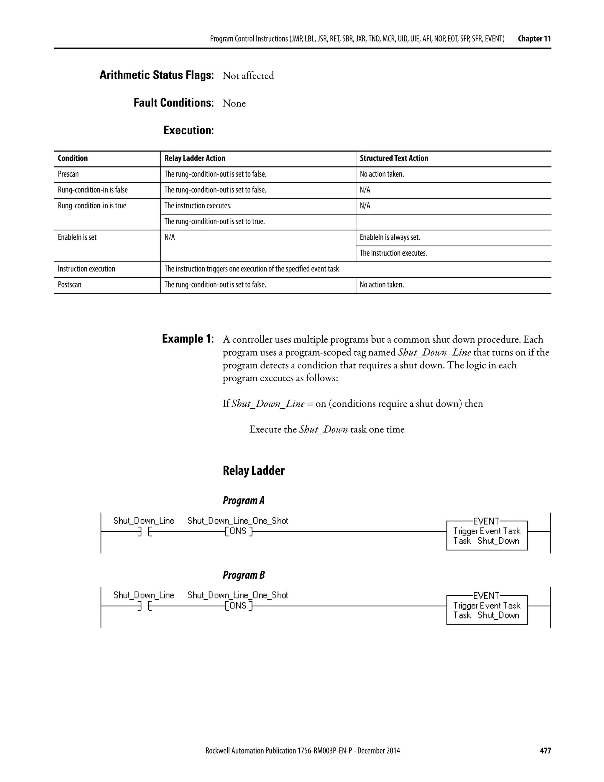

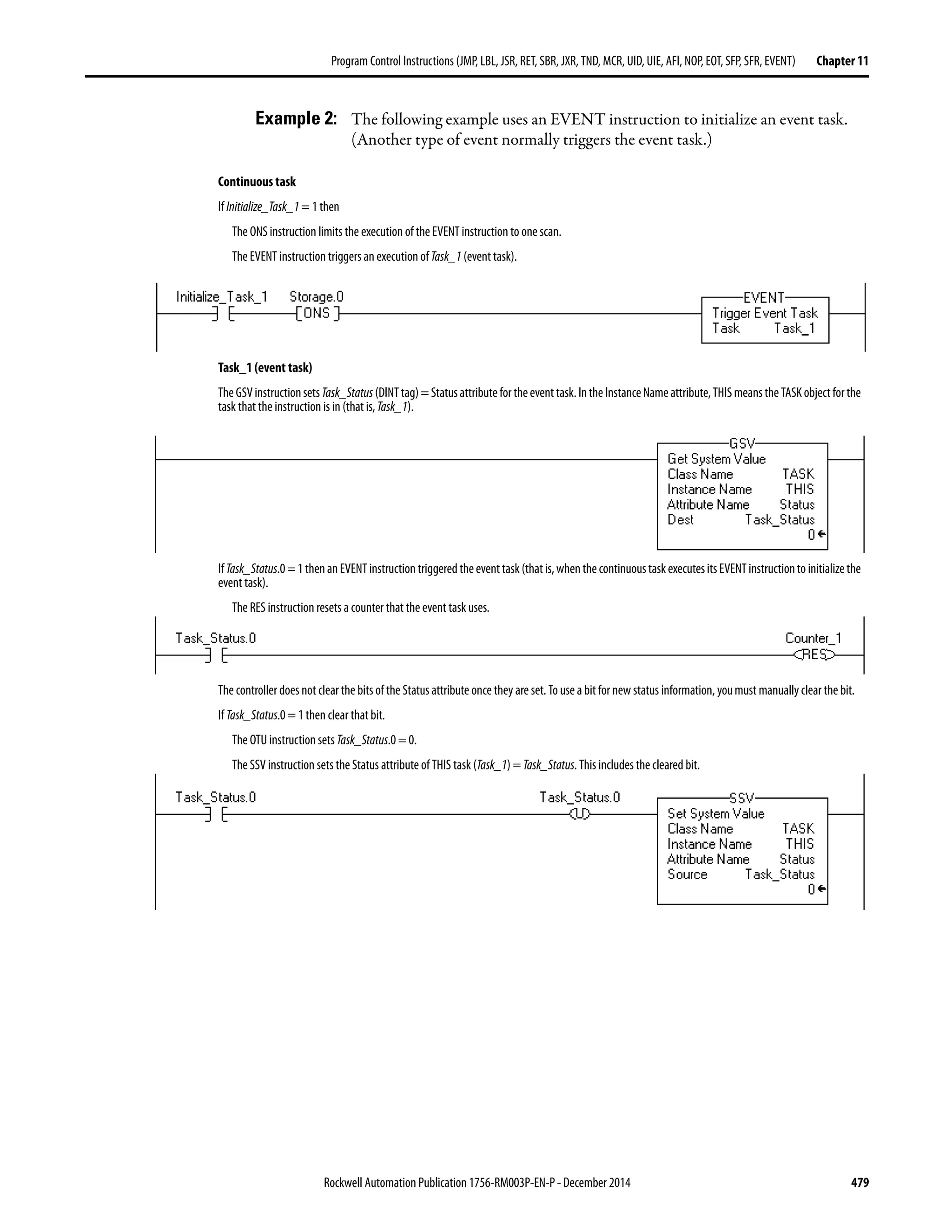

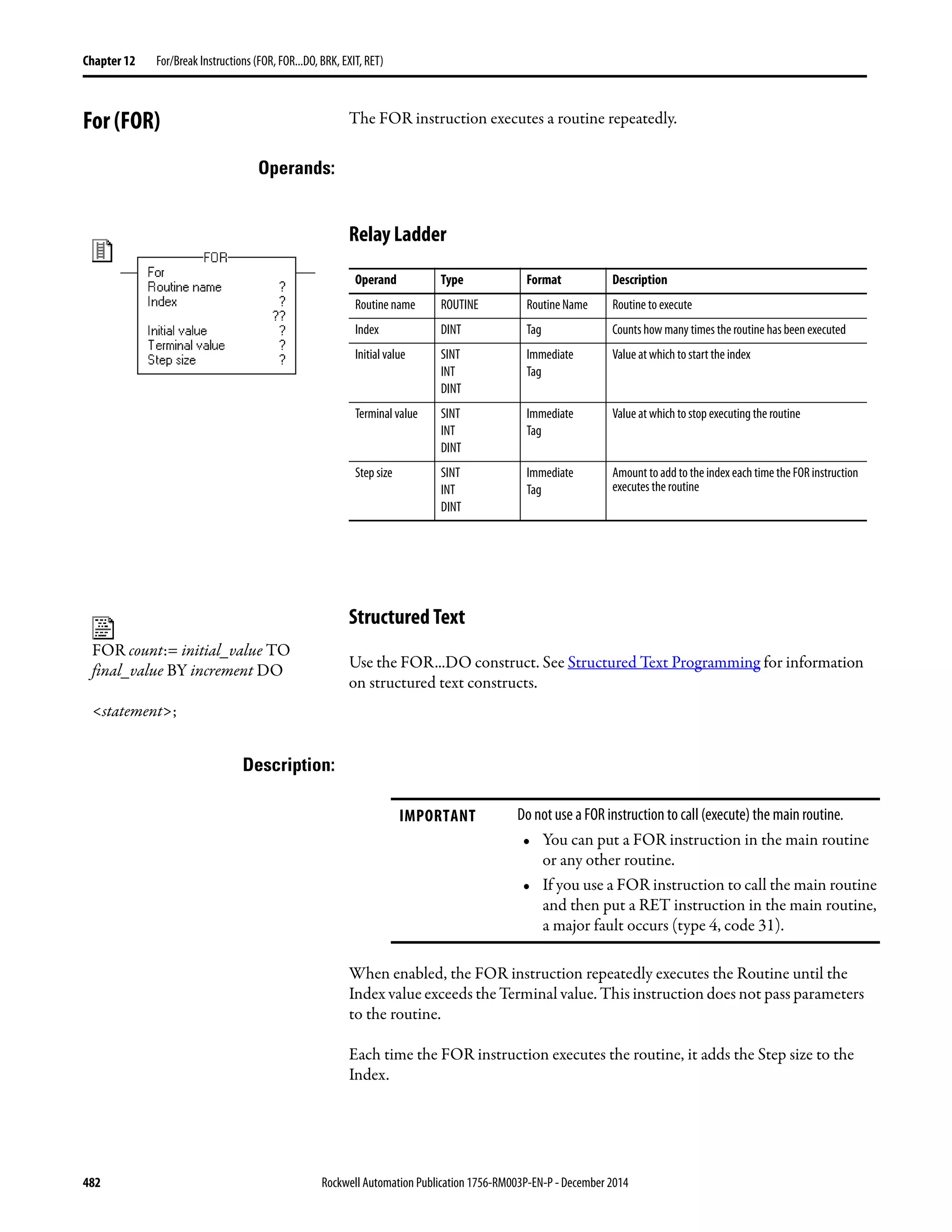


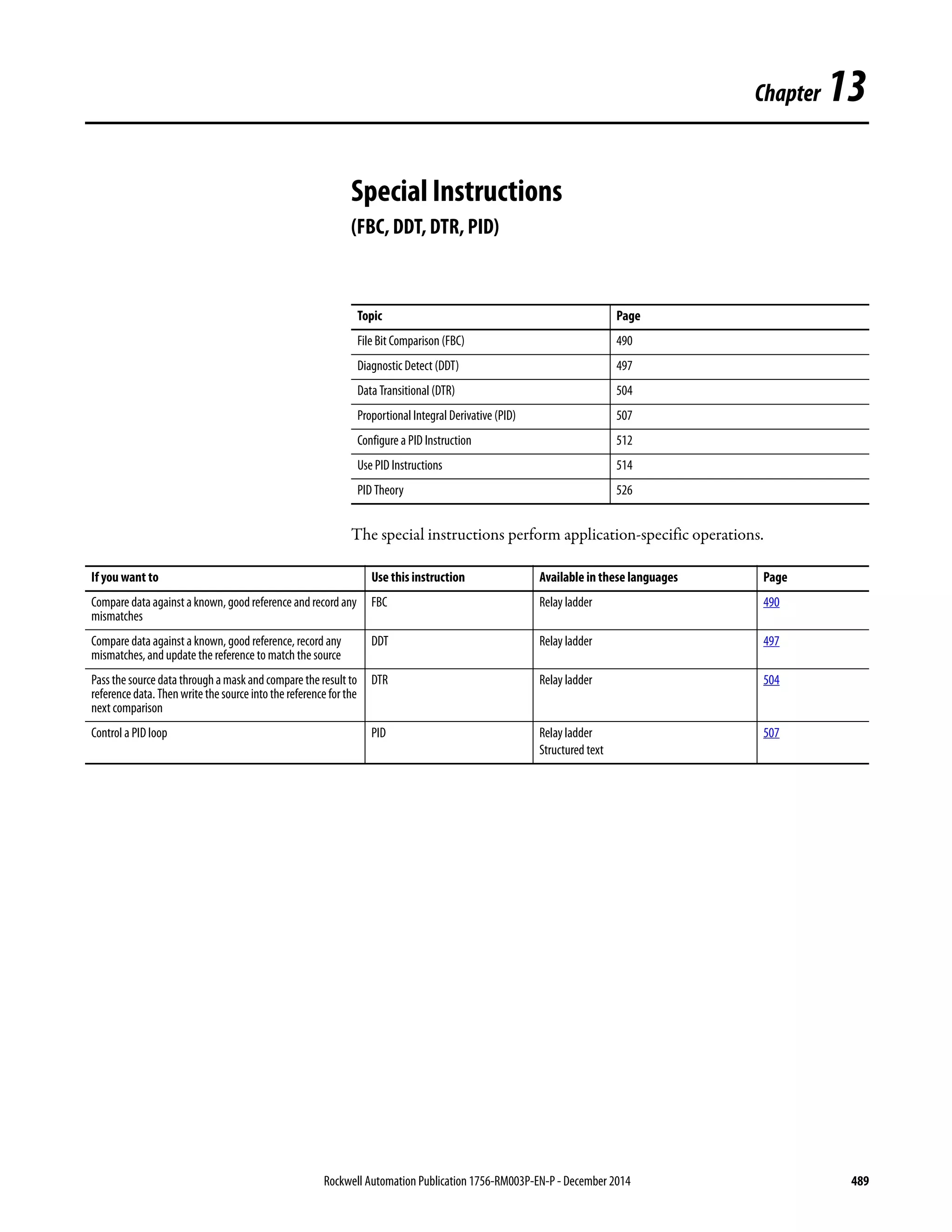
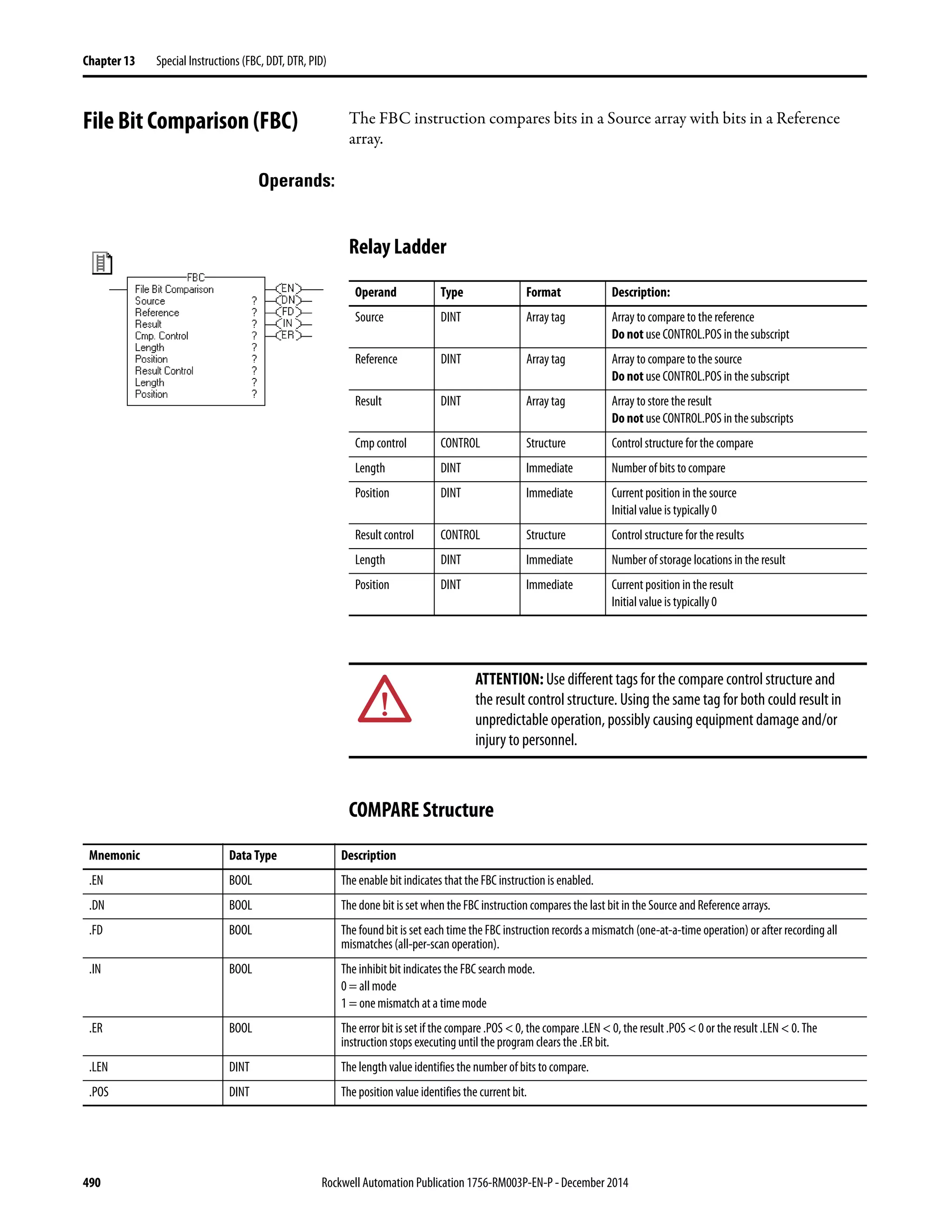

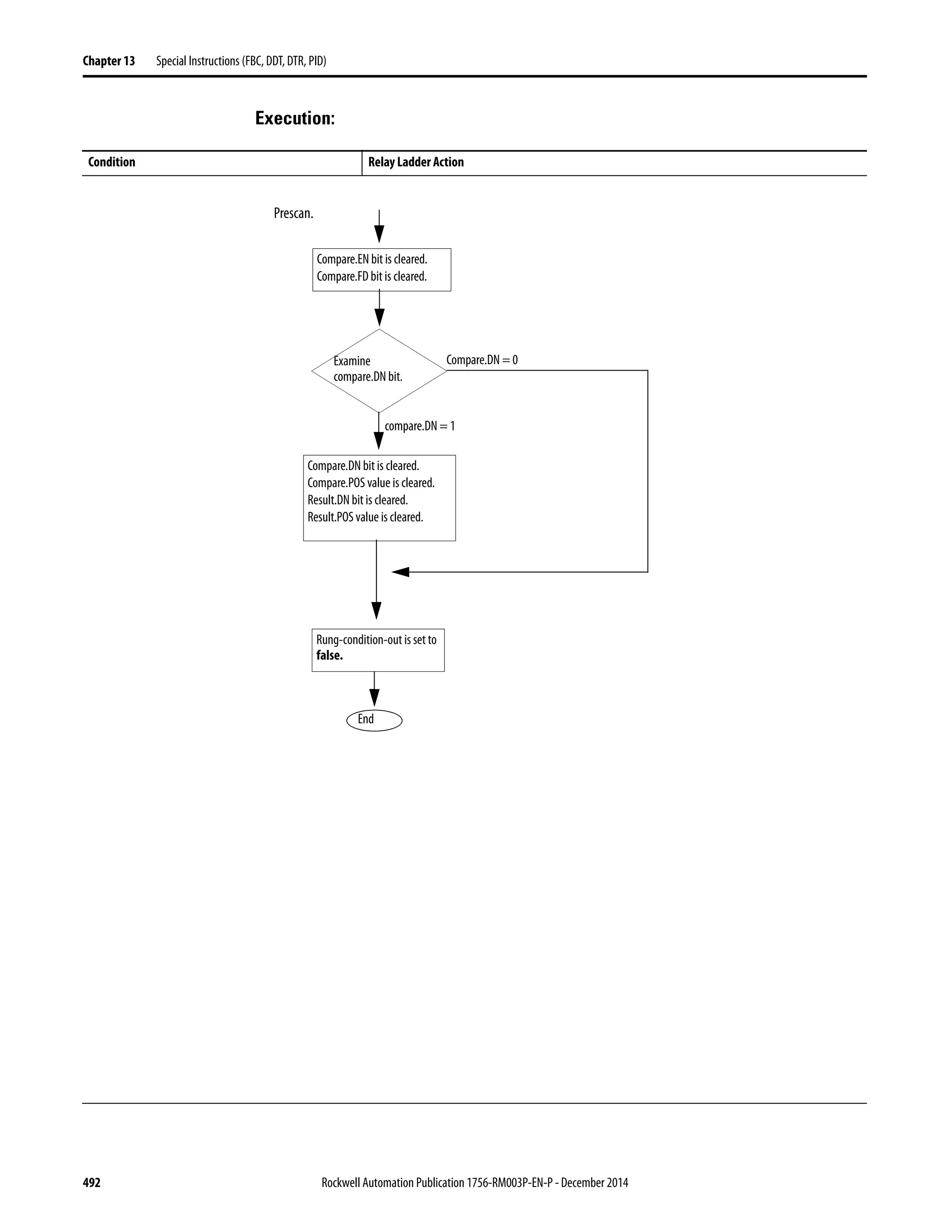


![Rockwell Automation Publication 1756-RM003P-EN-P - December 2014 495
Special Instructions (FBC, DDT, DTR, PID) Chapter 13
Postscan The rung-condition-out is set to false.
Condition Relay Ladder Action
Compare.POS ≥
Compare.LEN
Yes
No
Compare.POS = compare.LEN
Compare.DN bit is set.
Compare
Goto
Exit
Source[compare.POS] =
Reference[compare.POS]
No
Yes
Examine result.DN
bit.
Result.DN = 1
Result.DN = 0
Compare.POS =
compare.POS + 1
Compare.FD bit is set.
Result.DN bit is cleared.
Result.POS value is cleared.
Result.POS < 0
Yes
No
Result.LEN ≤ 0
Yes
No Compare.ER bit is set.
Goto
Exit
Yes
no
Major Fault
Result[result.POS] = compare.POS
result.POS = result.POS + 1
Result.POS >
result.LEN
No
yes
Result.DN bit is set.
page 494
page 494
Result.POS >
size of result array](https://image.slidesharecdn.com/1756-rm003-en-p-150617024022-lva1-app6892/75/1756-rm003-en-p-495-2048.jpg)


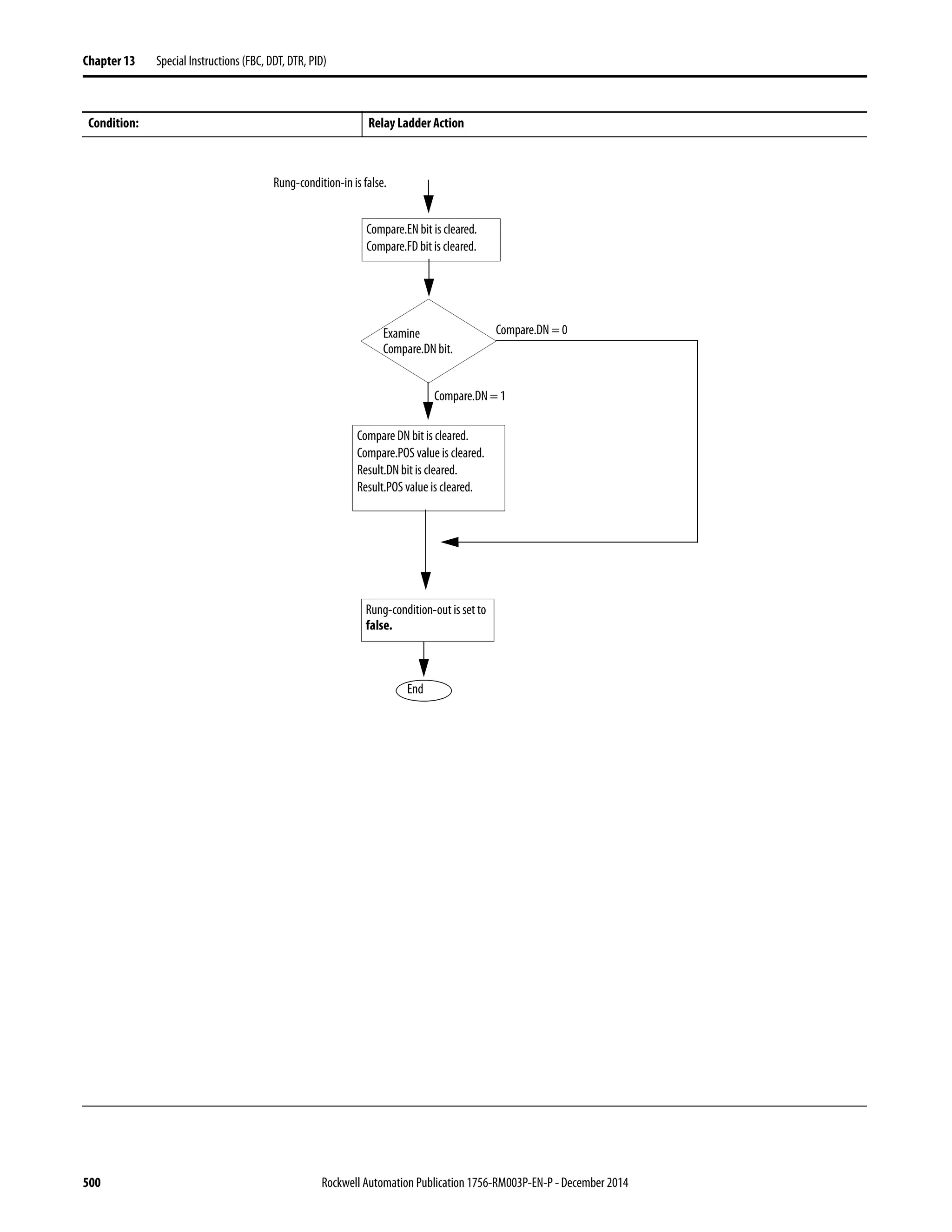

![502 Rockwell Automation Publication 1756-RM003P-EN-P - December 2014
Chapter 13 Special Instructions (FBC, DDT, DTR, PID)
Postscan The rung-condition-out is set to false.
Condition: Relay Ladder Action
Compare.POS ≥
Compare.LEN
Yes
No
Compare.POS = compare.LEN
Compare.DN bit is set.
Compare
Goto
Exit
Source[compare.POS] =
Reference[compare.POS]
No
Yes
Examine result.DN
bit.
Result.DN = 1
Result.DN = 0
Compare.POS =
Compare.POS + 1
Compare.FD bit is set.
Reference[compare.POS]
= Source[compare.POS]
Result.DN bit is cleared.
Result.POS value is cleared.
Result.POS < 0
Yes
No
Result.LEN ≤ 0
Yes
no Compare.ER bit is set.
Goto
Yes
no
Major Fault
Result[result.POS] = Compare.POS
Result.POS = Result.POS + 1
Result.POS ≥
Result.LEN
No
Yes
Result.DN bit is set.
page 501
page 494
Result.POS >
Size of result array](https://image.slidesharecdn.com/1756-rm003-en-p-150617024022-lva1-app6892/75/1756-rm003-en-p-502-2048.jpg)
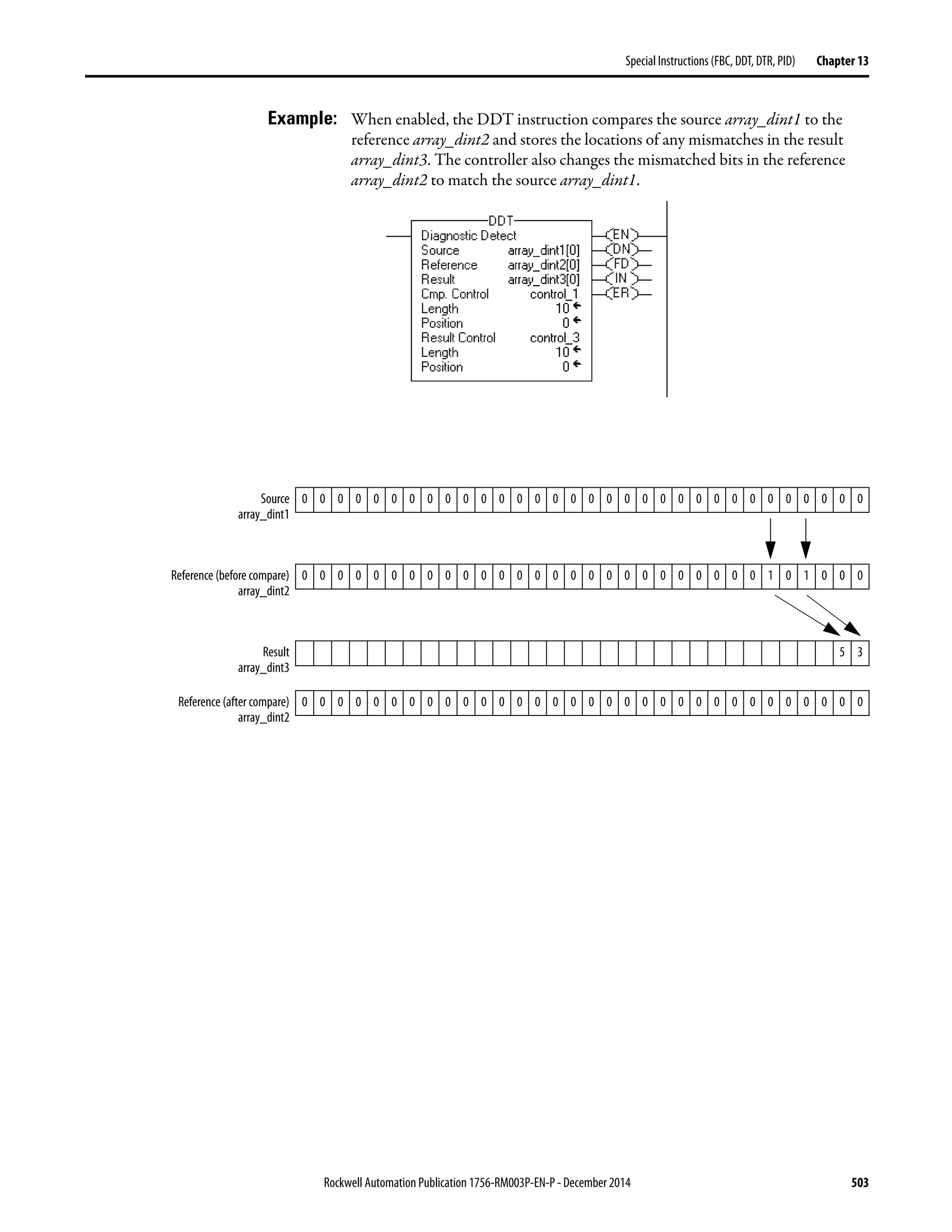


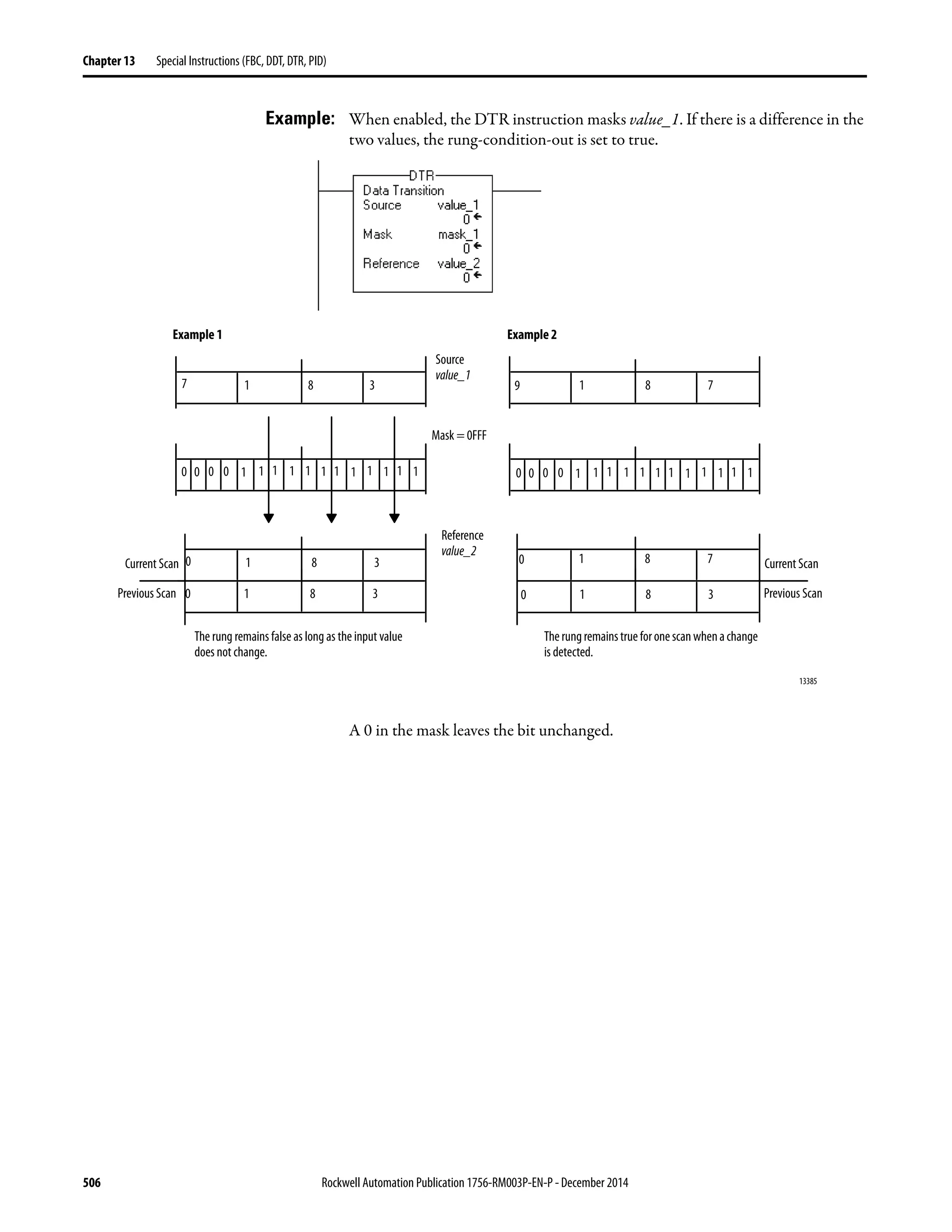
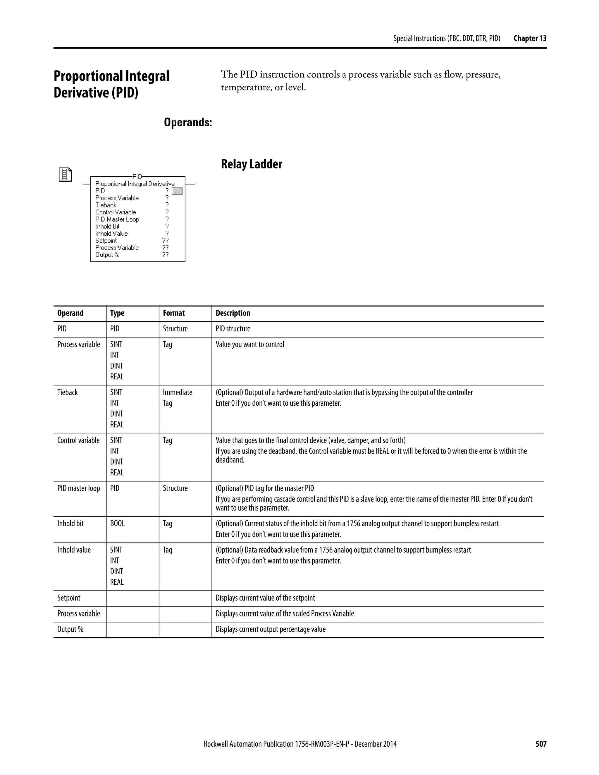
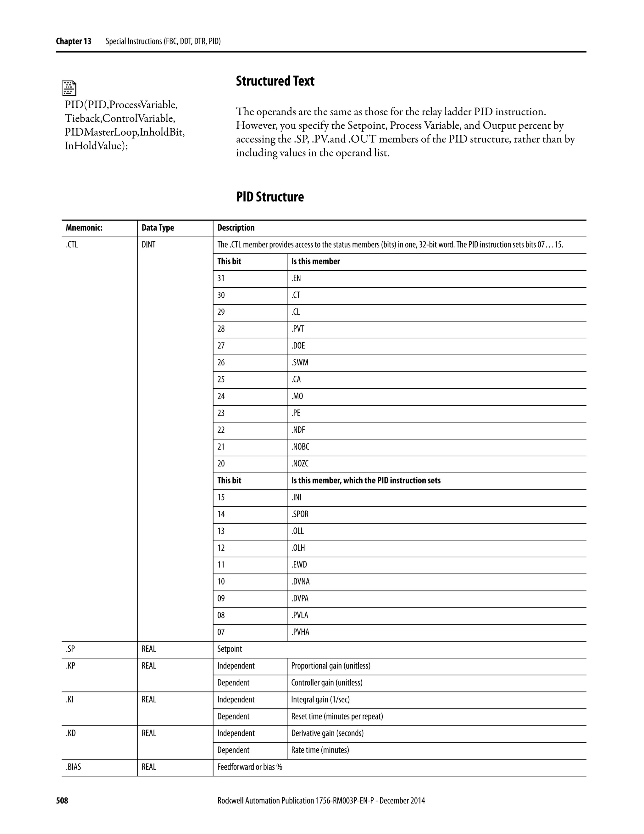

![510 Rockwell Automation Publication 1756-RM003P-EN-P - December 2014
Chapter 13 Special Instructions (FBC, DDT, DTR, PID)
.DATA REAL[17] The .DATA member stores:
Element Description
.DATA[0] Integral accumulation
.DATA[1] Derivative smoothing temporary value
.DATA[2] Previous .PV value
.DATA[3] Previous .ERR value
.DATA[4] Previous valid .SP value
.DATA[5] Percent scaling constant
.DATA[6] .PV scaling constant
.DATA[7] Derivative scaling constant
.DATA[8] Previous .KP value
.DATA[9] Previous .KI value
.DATA[10] Previous .KD value
.DATA[11] Dependent gain .KP
.DATA[12] Dependent gain .KI
.DATA[13] Dependent gain .KD
.DATA[14] Previous .CV value
.DATA[15] .CV descaling constant
.DATA[16] Tieback descaling constant
.EN BOOL Enabled
.CT BOOL Cascade type (0=slave; 1=master)
.CL BOOL Cascade loop (0=no; 1=yes)
.PVT BOOL Process variable tracking (0=no; 1=yes)
.DOE BOOL Derivative of (0=PV; 1=error)
.SWM BOOL Software manual mode (0=no-auto; 1=yes- sw manual)
.CA BOOL Control action (0 means E=SP-PV; 1 means E=PV-SP)
.MO BOOL Station mode (0=automatic; 1=manual)
.PE BOOL PID equation (0=independent; 1=dependent)
.NDF BOOL No derivative smoothing
(0=derivative smoothing filter enabled; 1=derivative smoothing filter disabled)
.NOBC BOOL No bias back calculation
(0=bias back calculation enabled; 1=bias back calculation disabled)
.NOZC BOOL No zero crossing deadband
(0=deadband is zero crossing; 1=deadband is not zero crossing)
.INI BOOL PID initialized (0=no; 1=yes)
.SPOR BOOL Setpoint out of range (0=no; 1=yes)
.OLL BOOL CV is below minimum output limit (0=no; 1=yes)
.OLH BOOL CV is above maximumoutput limit (0=no; 1=yes)
.EWD BOOL Error is within deadband (0=no; 1=yes)
.DVNA BOOL Deviation is alarmed low (0=no; 1=yes)
Mnemonic: Data Type Description](https://image.slidesharecdn.com/1756-rm003-en-p-150617024022-lva1-app6892/75/1756-rm003-en-p-510-2048.jpg)
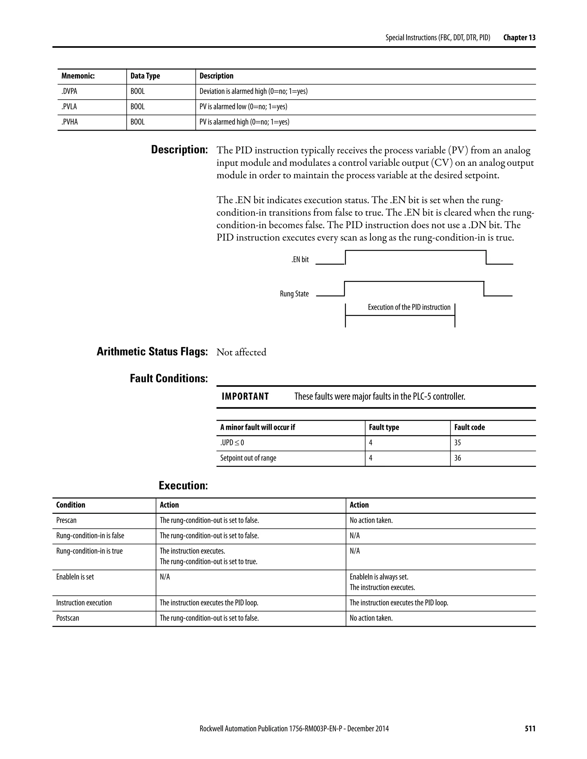


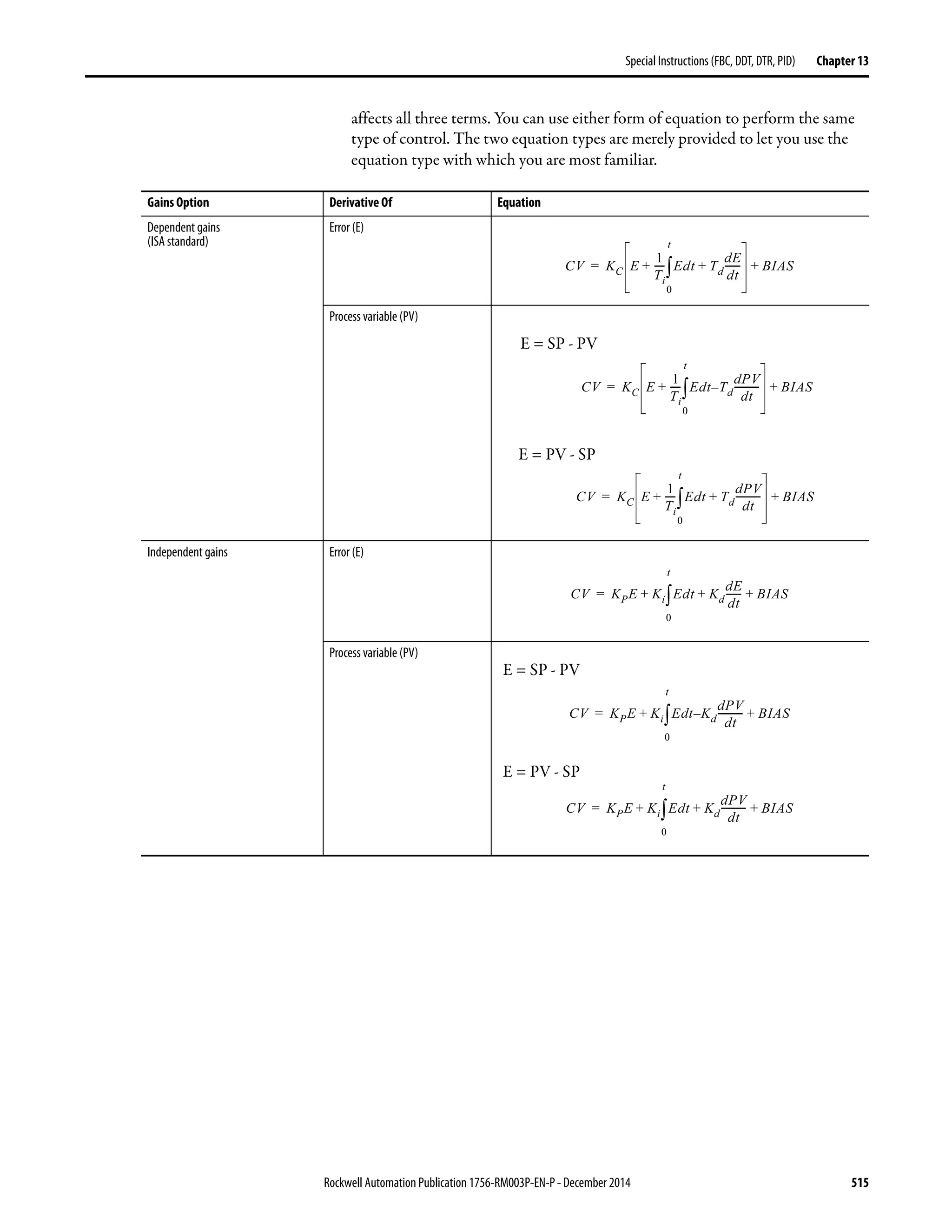
![516 Rockwell Automation Publication 1756-RM003P-EN-P - December 2014
Chapter 13 Special Instructions (FBC, DDT, DTR, PID)
Where:
If you do not want to use a particular term of the PID equation, just set its gain to
zero. For example if you want no derivative action, set Kd or Td equal to zero.
Anti-reset Windup and Bumpless Transfer from Manual to Auto
The PID instruction automatically avoids reset windup by preventing the integral
term from accumulating whenever the CV output reaches its maximum or
minimum values, as set by .MAXO and .MINO. The accumulated integral term
remains frozen until the CV output drops below its maximum limit or rises above
its minimum limit. Then normal integral accumulation automatically resumes.
The PID instruction supports two manual modes of control.
Variable Description
KP Proportional gain (unitless)
Kp = Kc unitless
Ki Integral gain (seconds-1
)
To convert between Ki (integral gain) and Ti (reset time), use:
Kd Derivative gain (seconds)
To convert between Kd (derivative gain) and Td (rate time), use:
Kd = Kc (Td) 60
KC Controller gain (unitless)
Ti Reset time (minutes/repeat)
Td Rate time (minutes)
SP Setpoint
PV Process variable
E Error [(SP-PV) or (PV-SP)]
BIAS Feedforward or bias
CV Control variable
dt Loop update time
Ki
KC
60Ti
-----------=
Manual Mode of Control Description
Software manual (.SWM) Also known as set output mode
Lets the user set the output % from the software
The set output (.SO) value is used as the output of the loop. The set output value typically comes from an operator
input from an operator interface device.
Manual (.MO) Takes the tieback value, as an input, and adjusts its internal variables to generate the same value at the output
The tieback input to the PID instruction is scaled to 0-100% according to the values of .MINTIE and .MAXTIE and is
used as the output of the loop. The tieback input typically comes from the output of a hardware hand/auto station
that is bypassing the output from the controller.
Important: Manual mode overrides software manual mode if both mode bits are set on.](https://image.slidesharecdn.com/1756-rm003-en-p-150617024022-lva1-app6892/75/1756-rm003-en-p-516-2048.jpg)

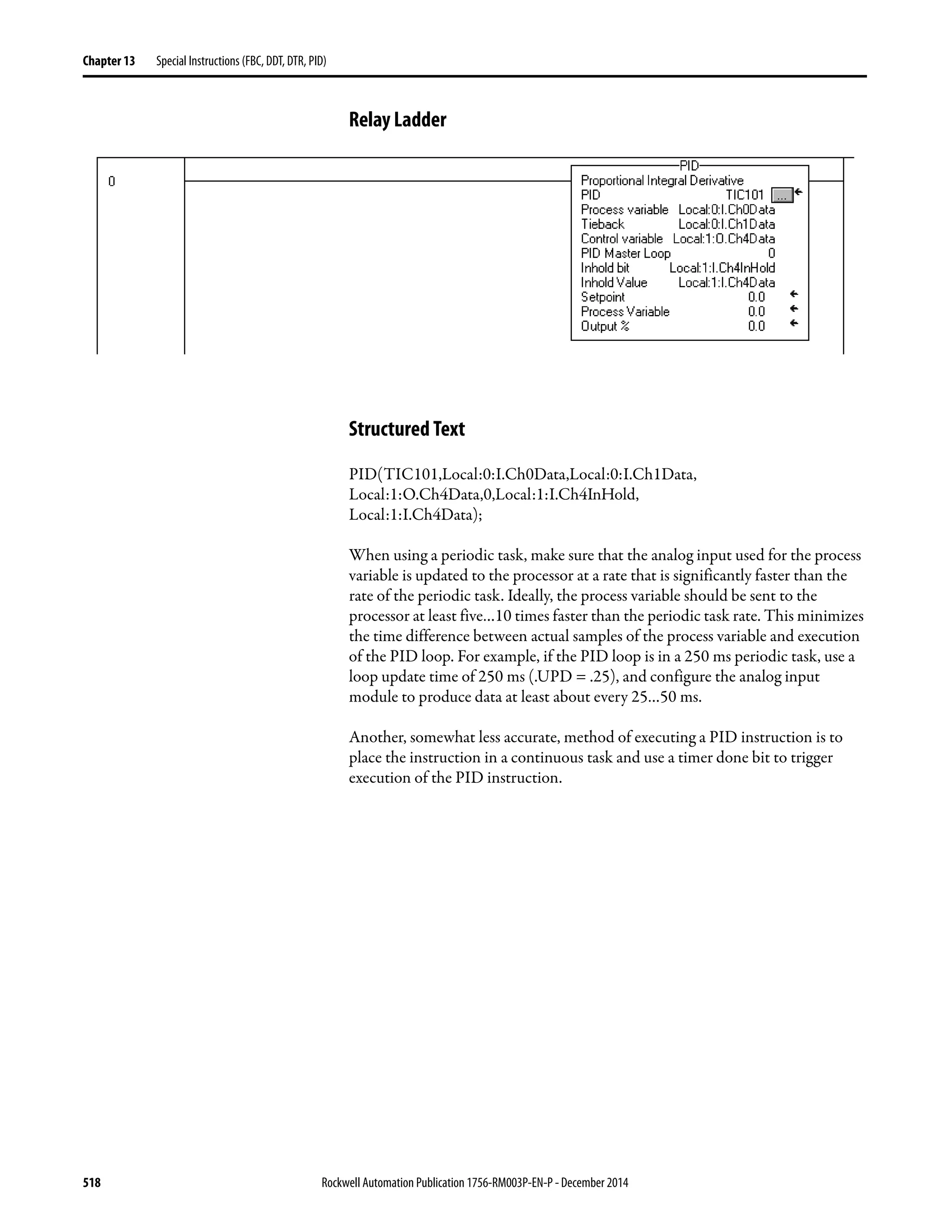


![Rockwell Automation Publication 1756-RM003P-EN-P - December 2014 521
Special Instructions (FBC, DDT, DTR, PID) Chapter 13
Structured Text
IF (Local:0:I.Ch0Fault) THEN
TIC101.SWM [:=] 1;
ELSE
TIC101.SWM := 0;
END_IF;
IF (Local:0:I.RollingTimestamp<>PreviousTimestamp) OR
(Local:0:I.Ch0Fault) THEN
PreviousTimestamp := Local:0:I.RollingTimestamp;
PID(TIC101,Local:0:I.Ch0Data,Local:0:I.Ch1Data,
Local:1:O.Ch0Data,0,Local:1:I.Ch0InHold,
Local:1:I.Ch0Data);
END_IF;
Bumpless Restart
The PID instruction can interact with the 1756 analog output modules to
support a bumpless restart when the controller changes from Program
to Run mode or when the controller powers up.
When a 1756 analog output module loses communications with the controller or
senses that the controller is in Program mode, the analog output module sets its
outputs to the fault condition values you specified when you configured the
module. When the controller then returns to Run mode or re-establishes
communications with the analog output module, you can have the PID
instruction automatically reset its control variable output equal to the analog
output by using the Inhold bit and Inhold Value parameters on the
PID instruction.](https://image.slidesharecdn.com/1756-rm003-en-p-150617024022-lva1-app6892/75/1756-rm003-en-p-521-2048.jpg)
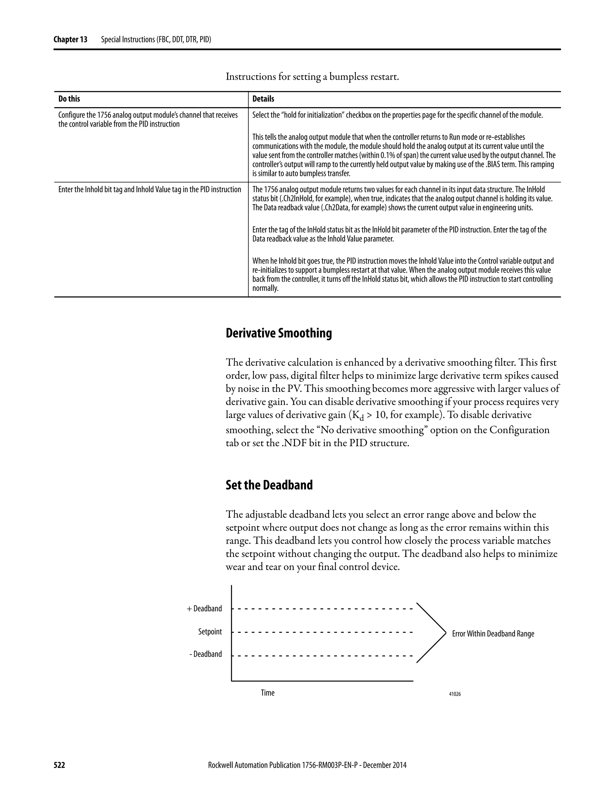


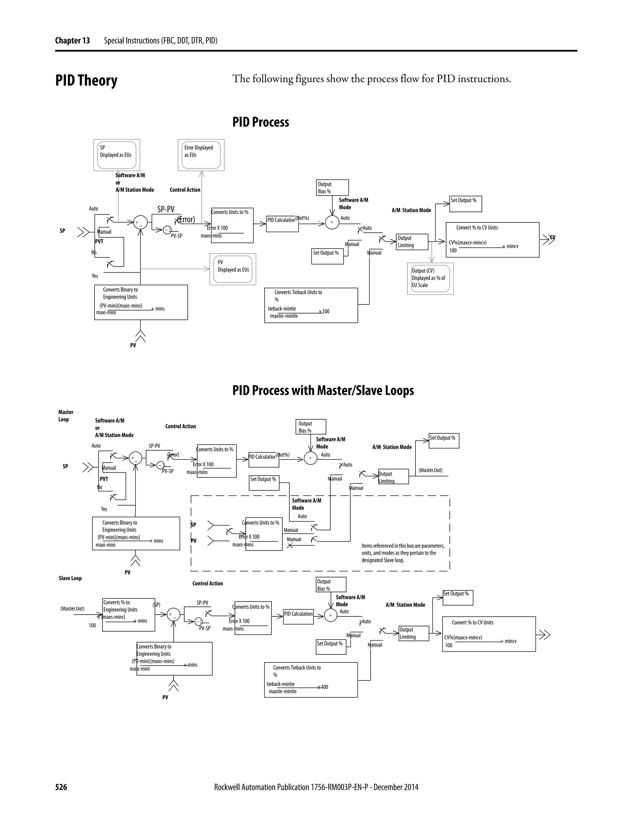
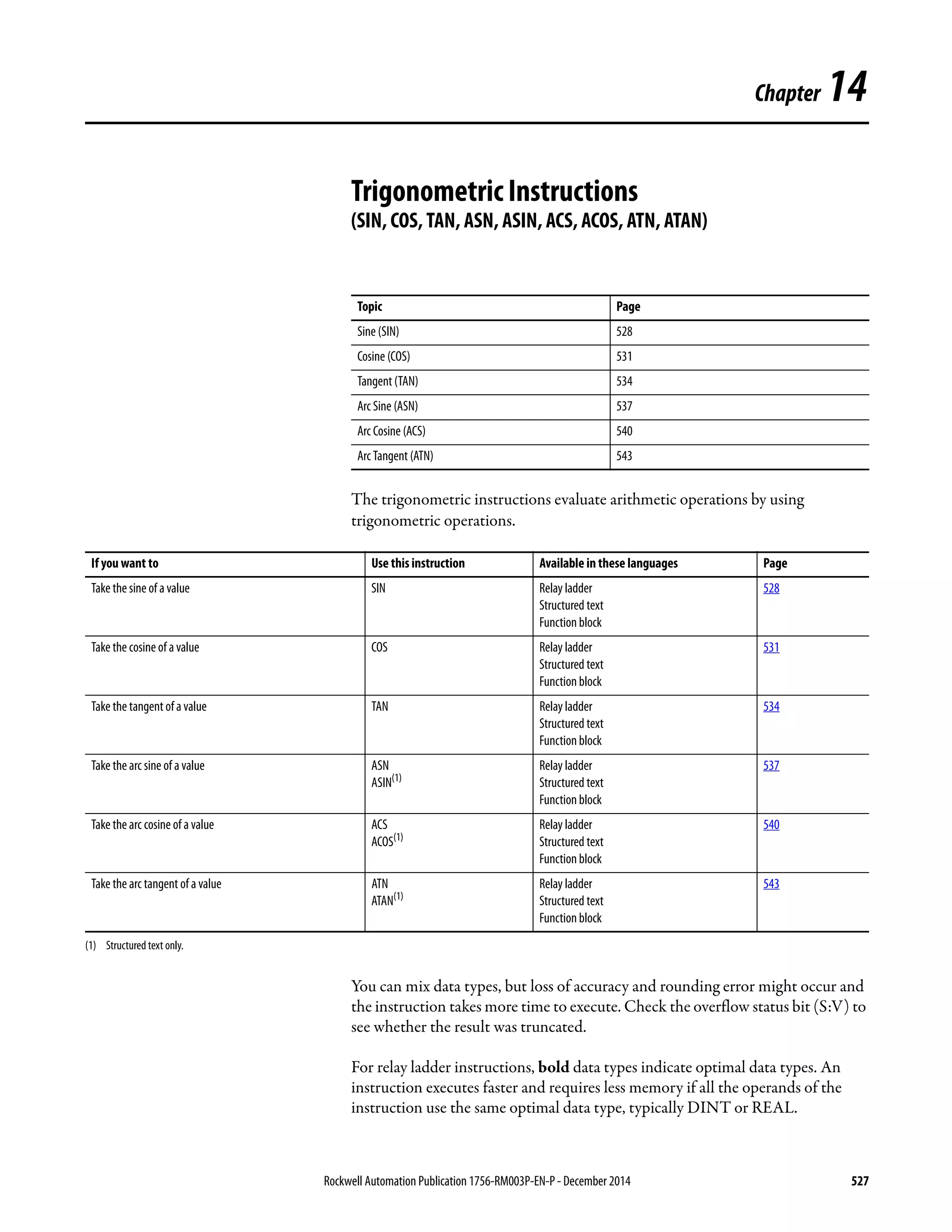
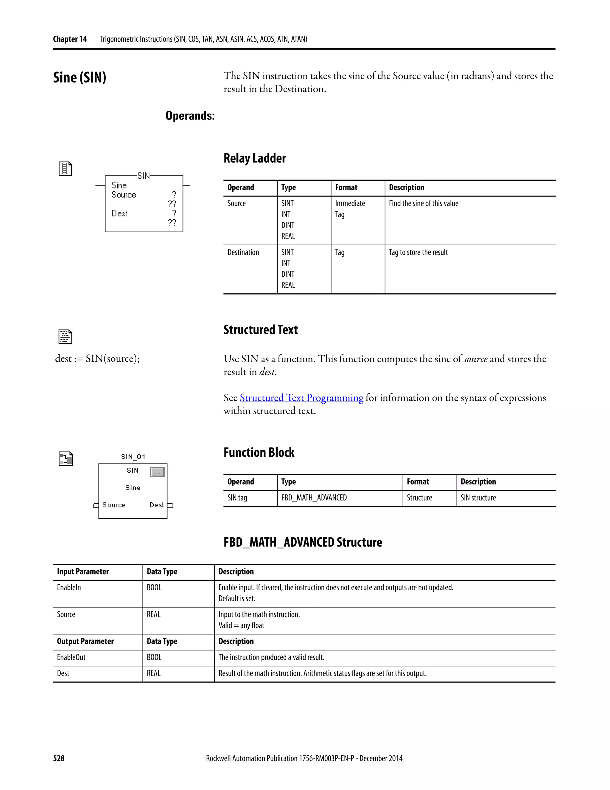


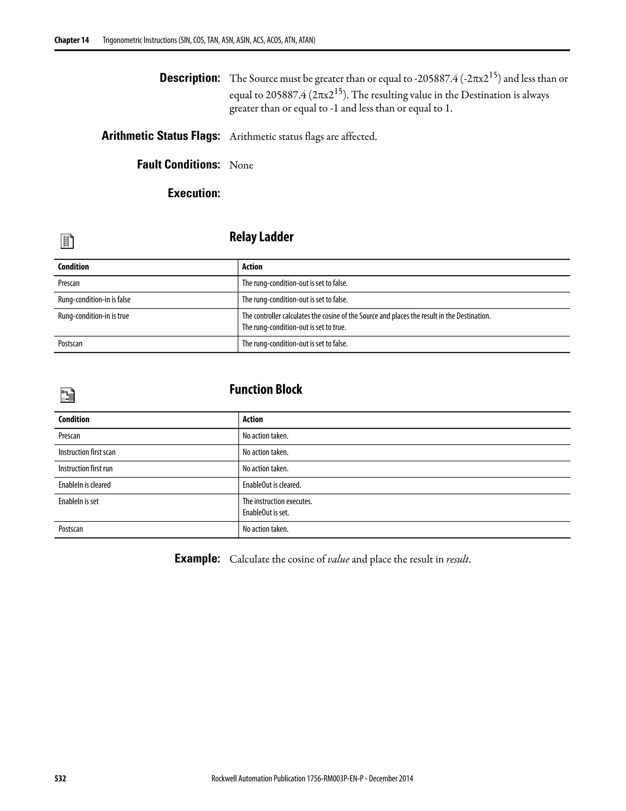


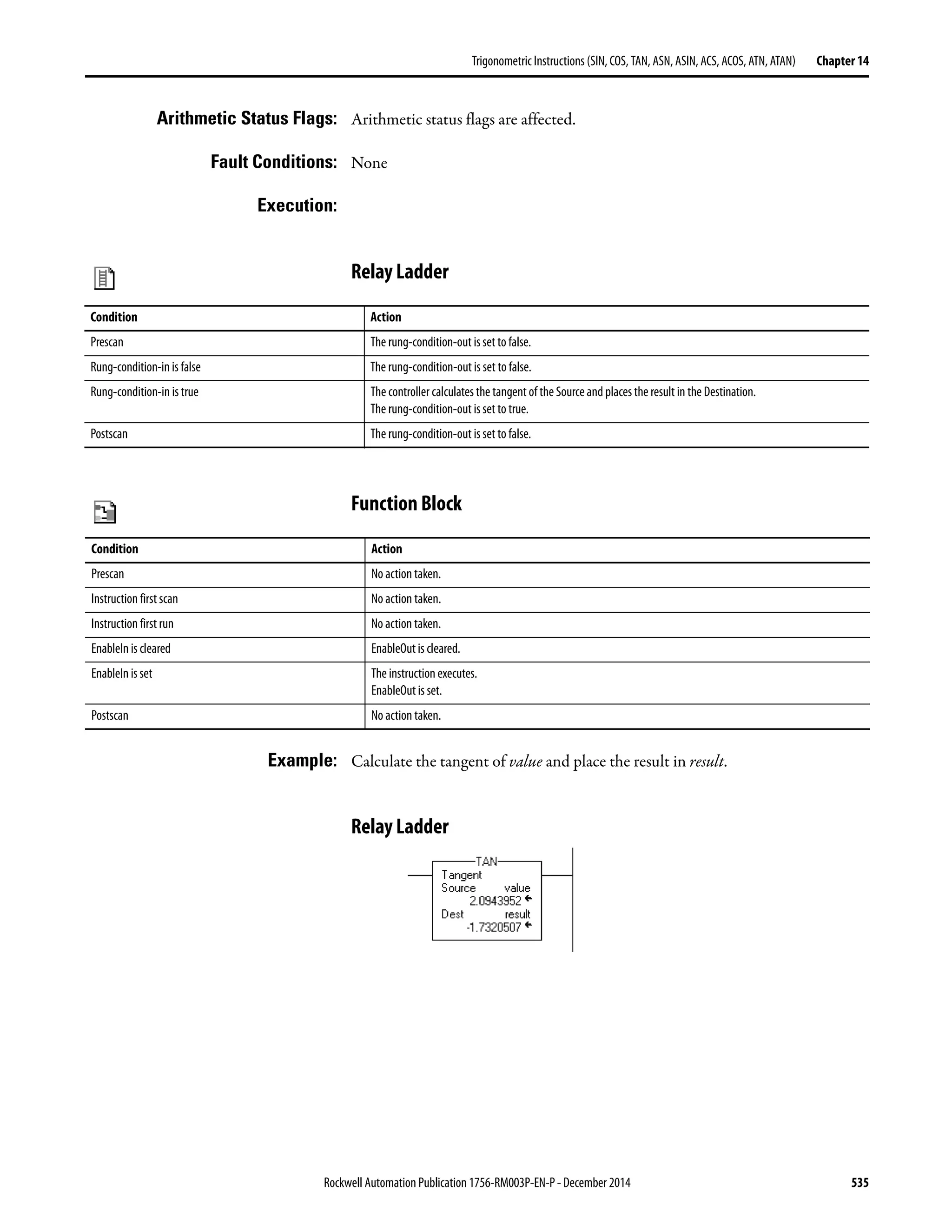

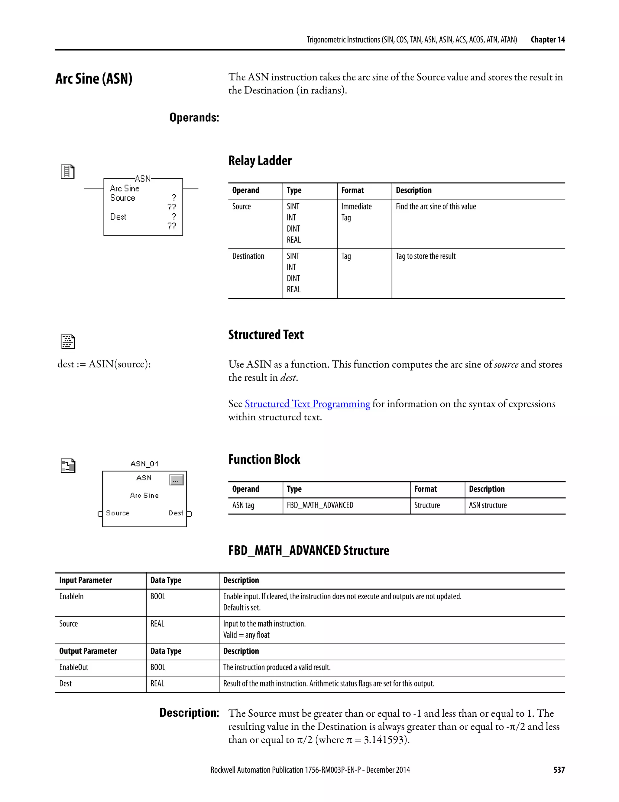

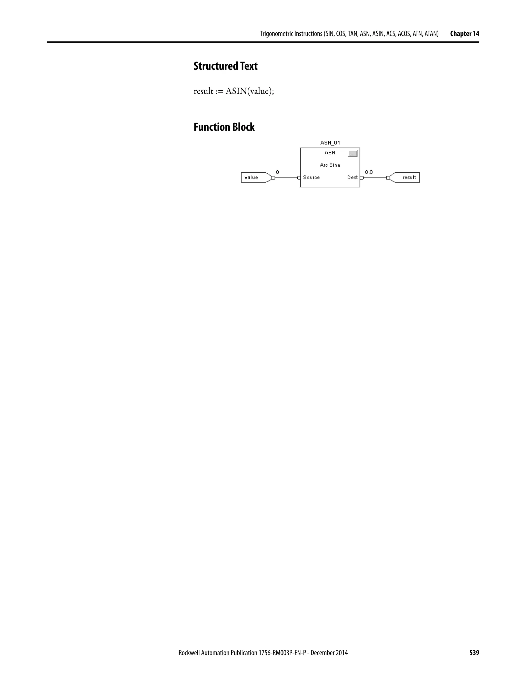


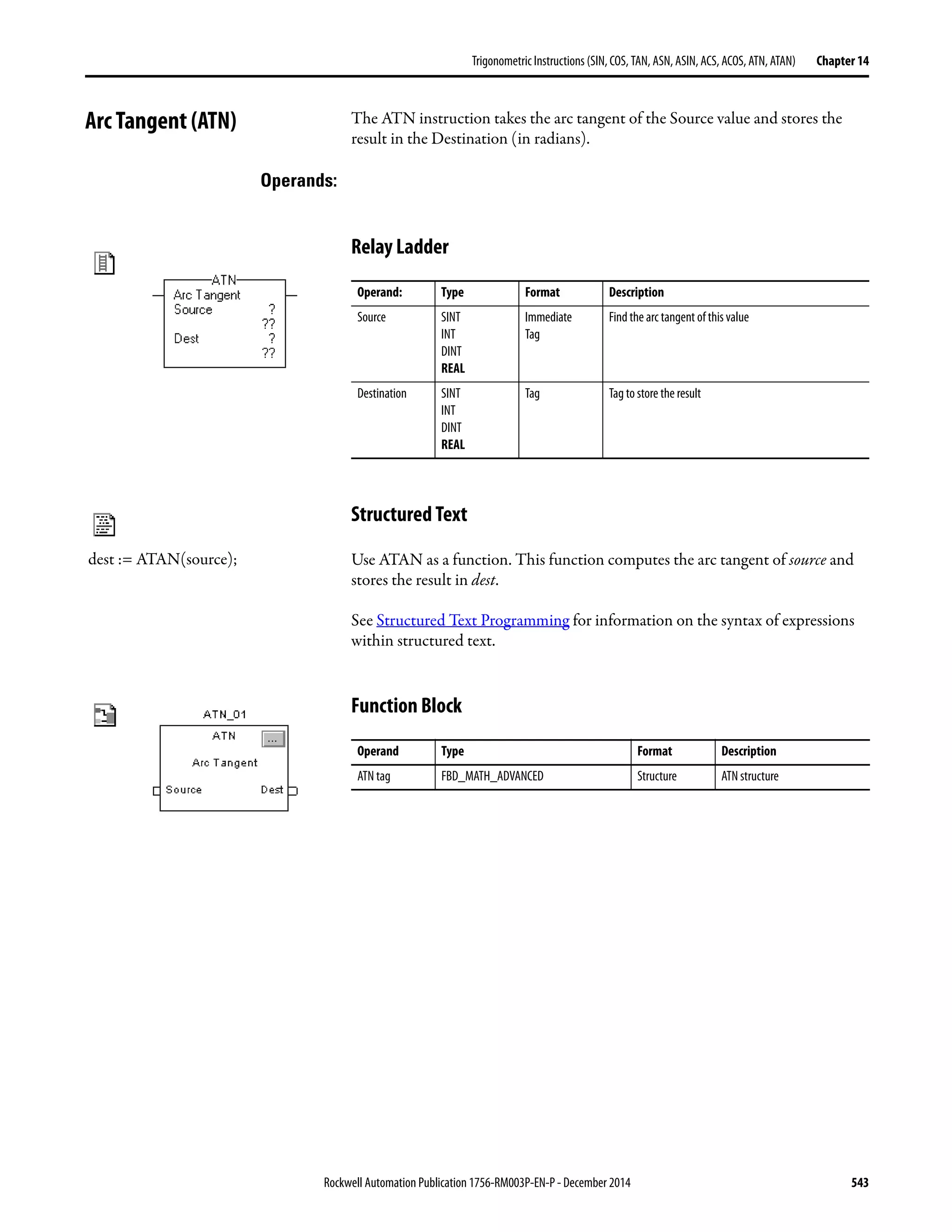

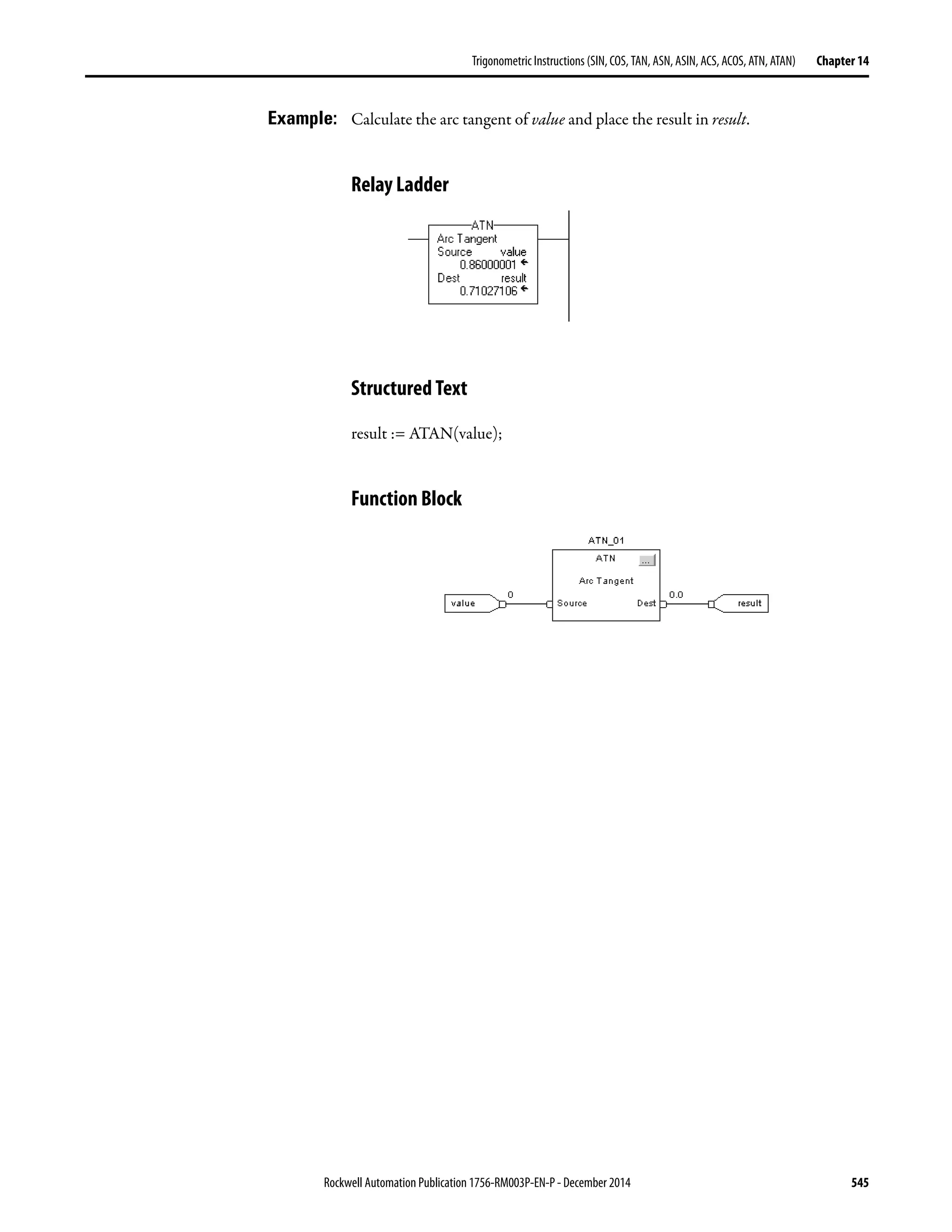


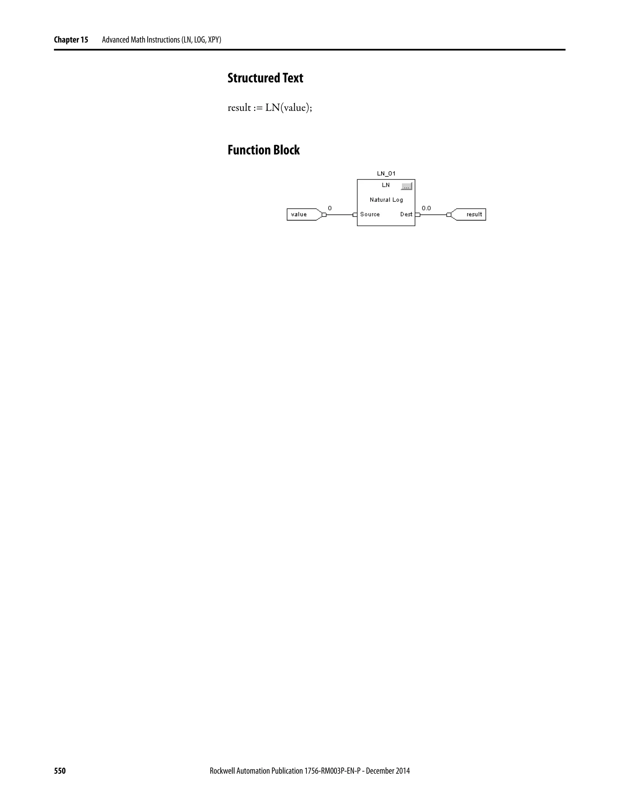


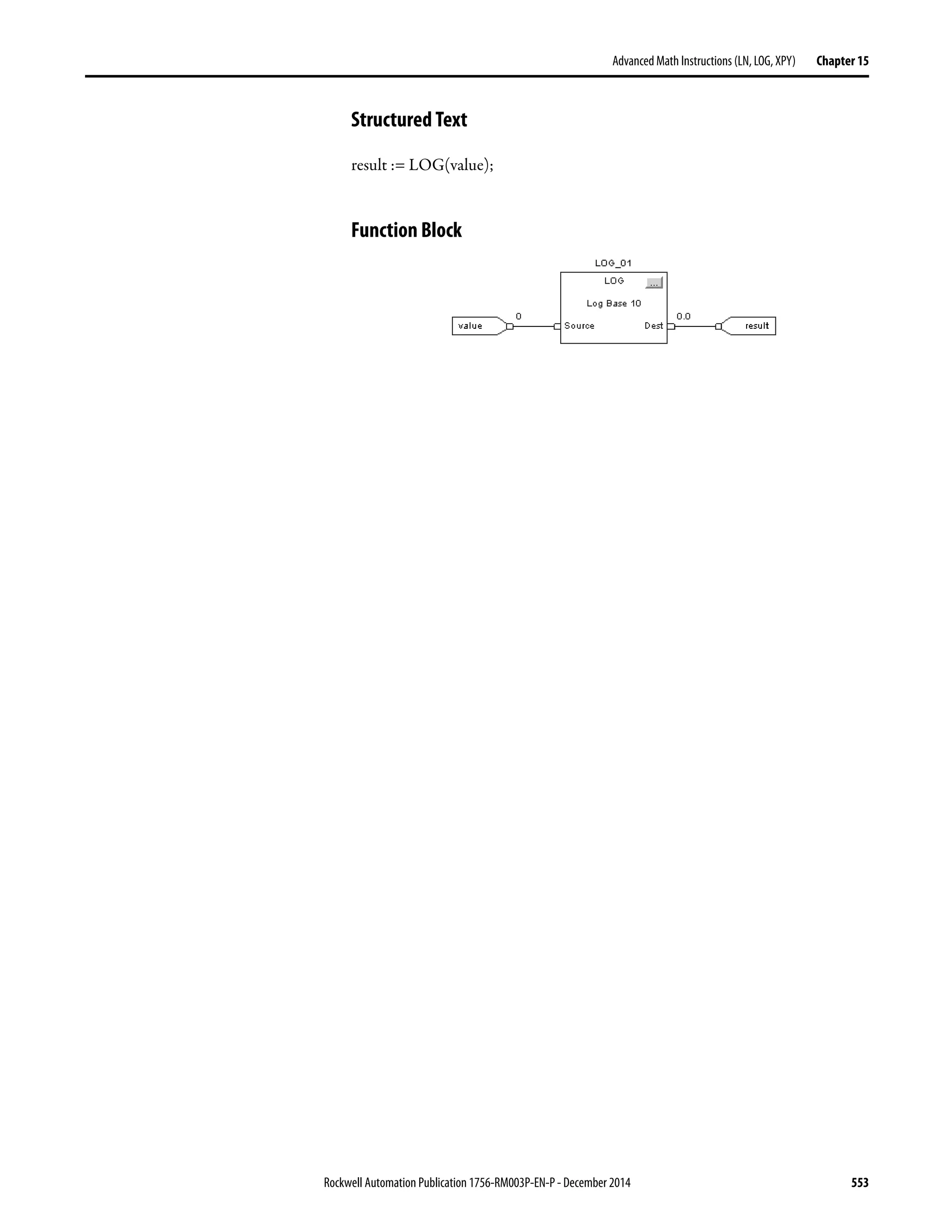


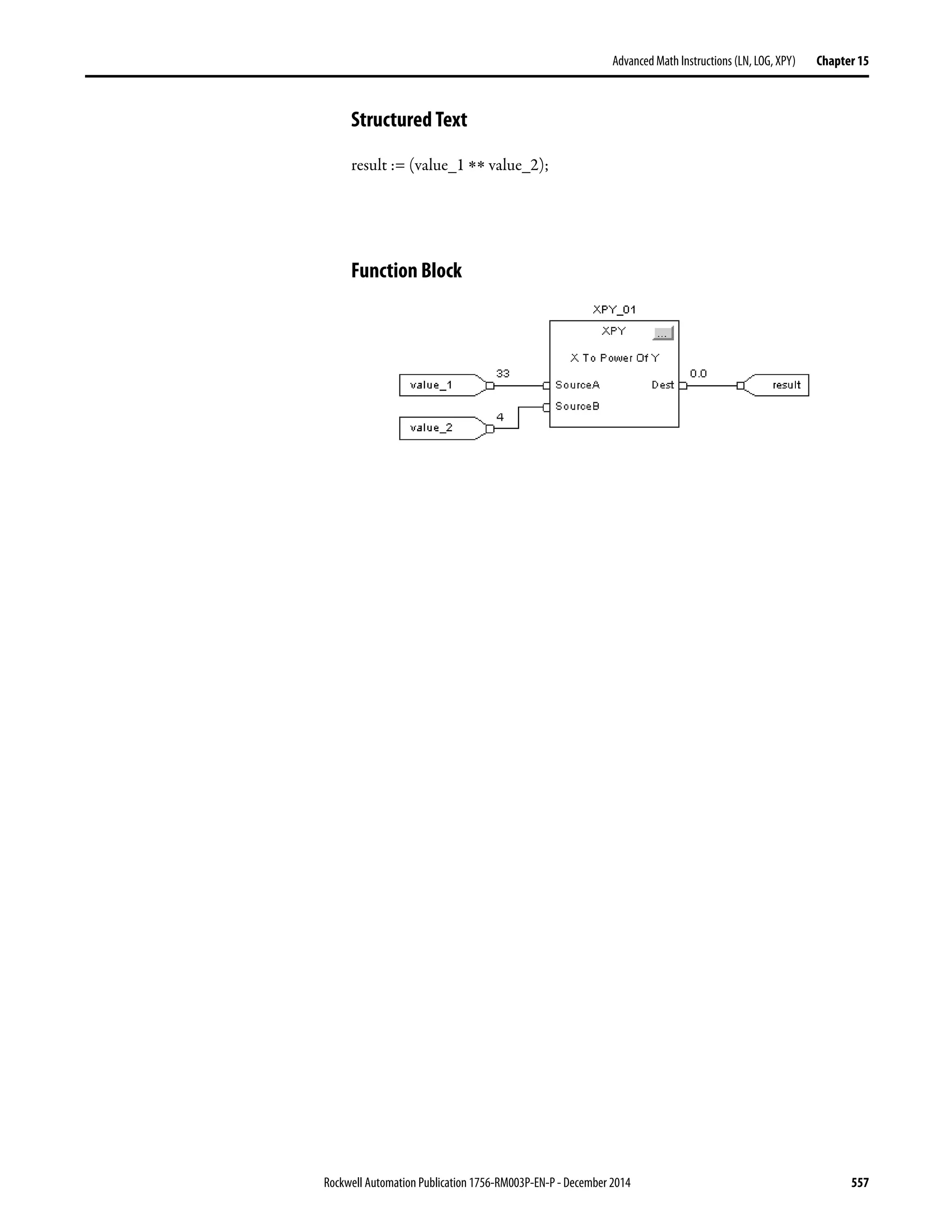


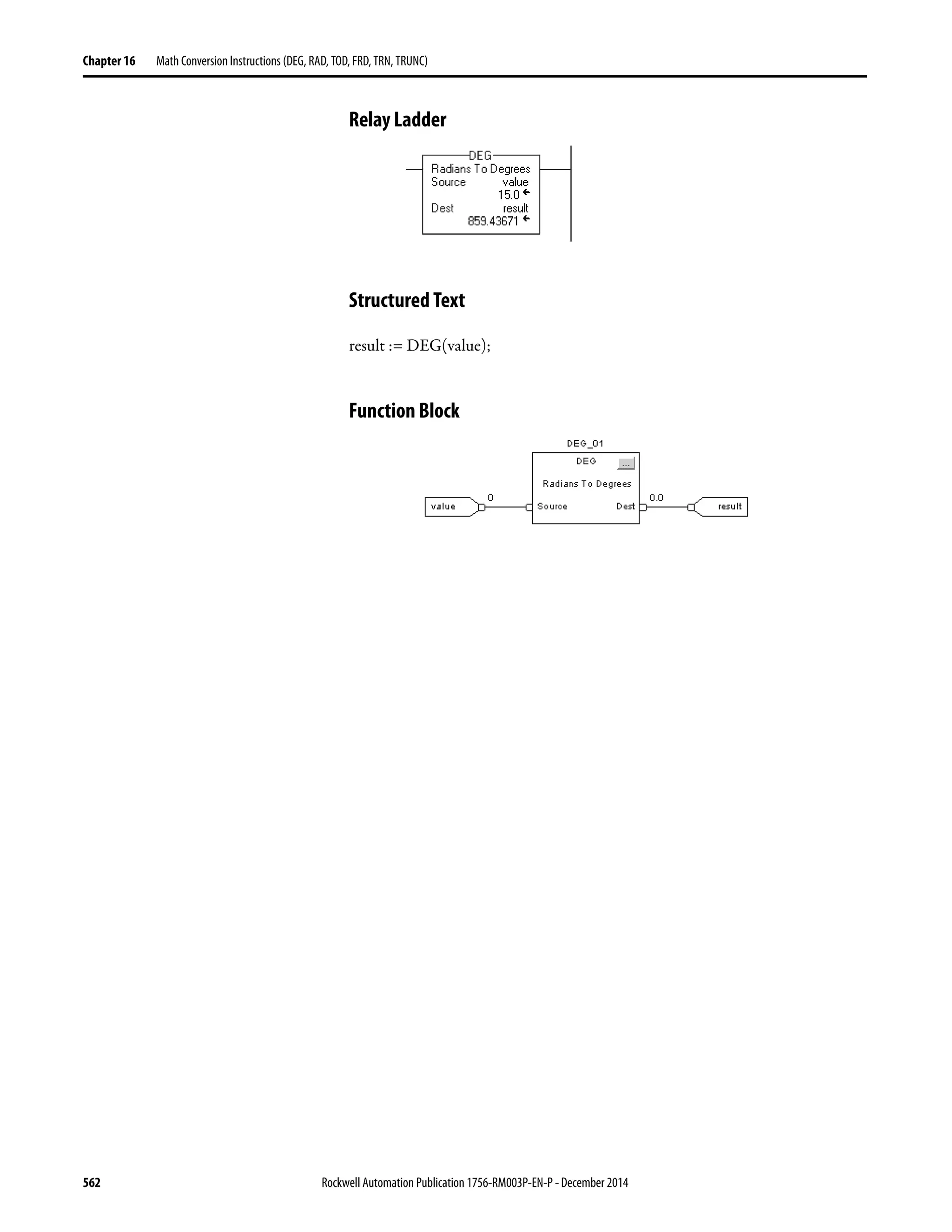
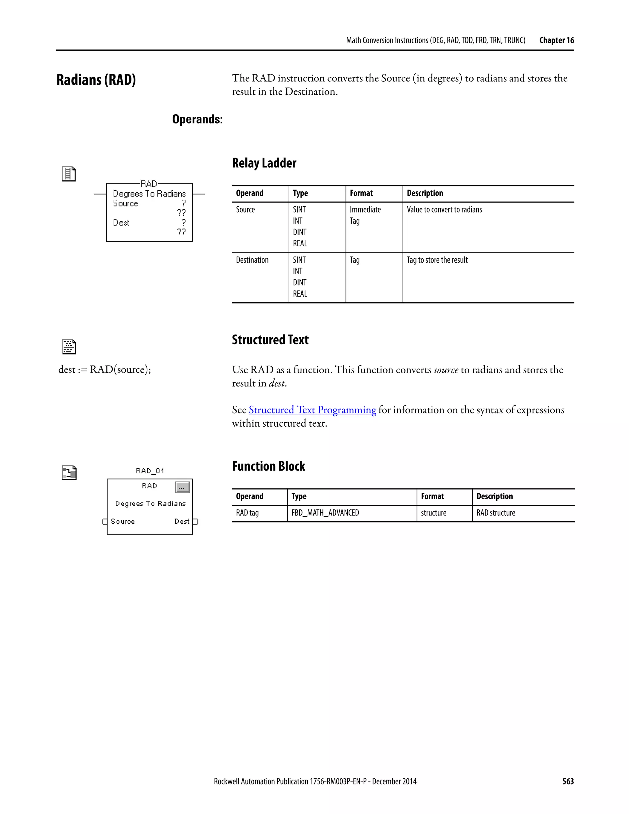


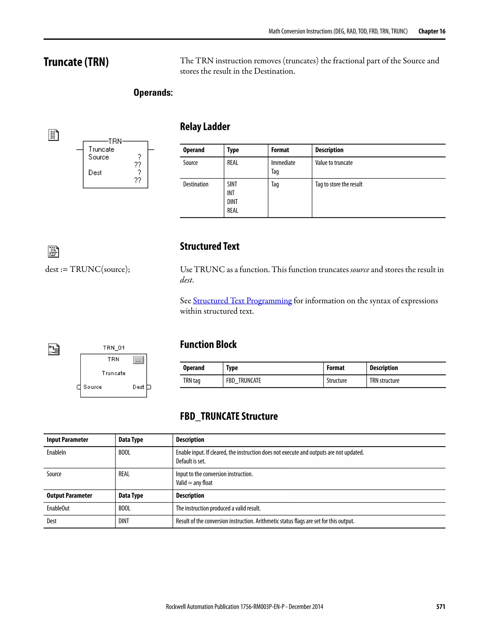


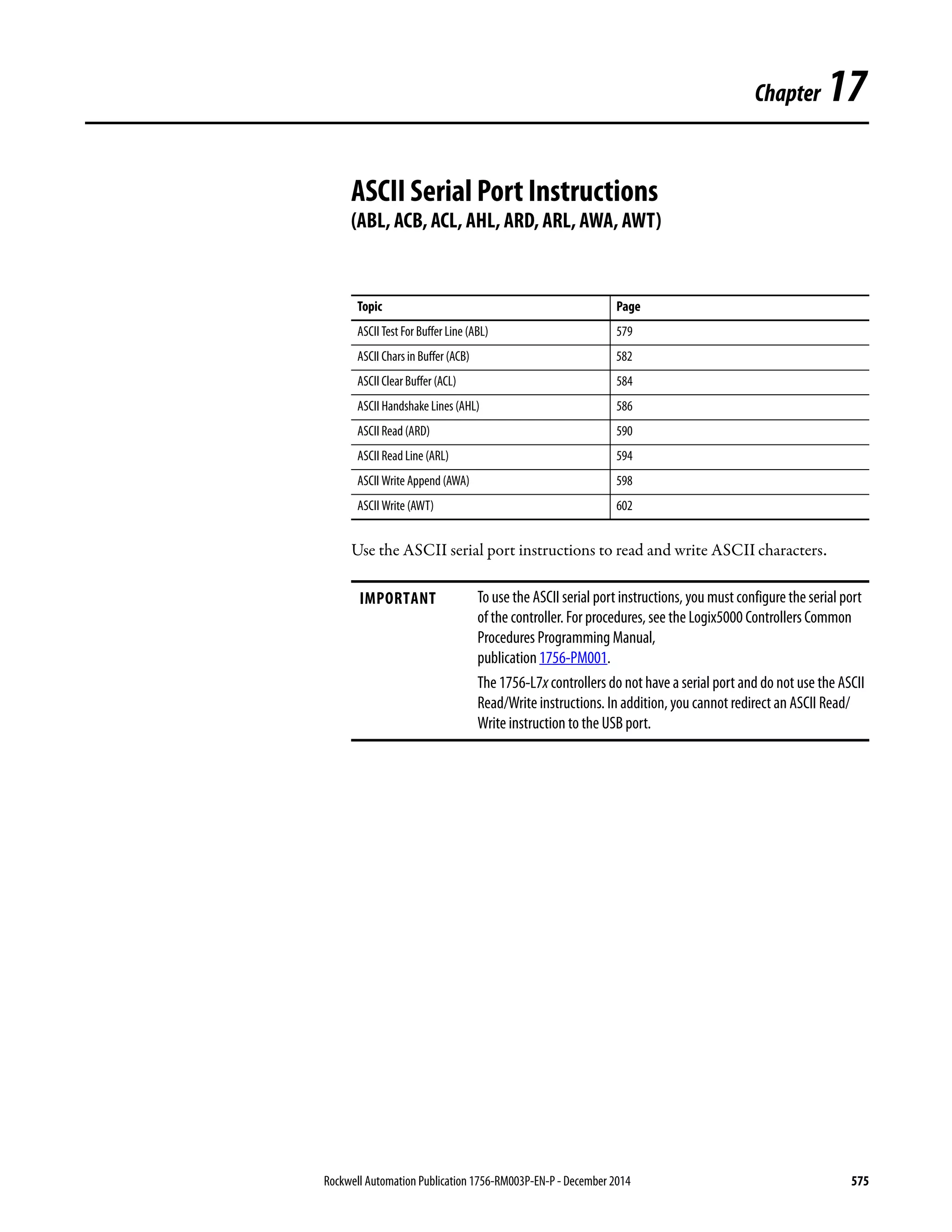
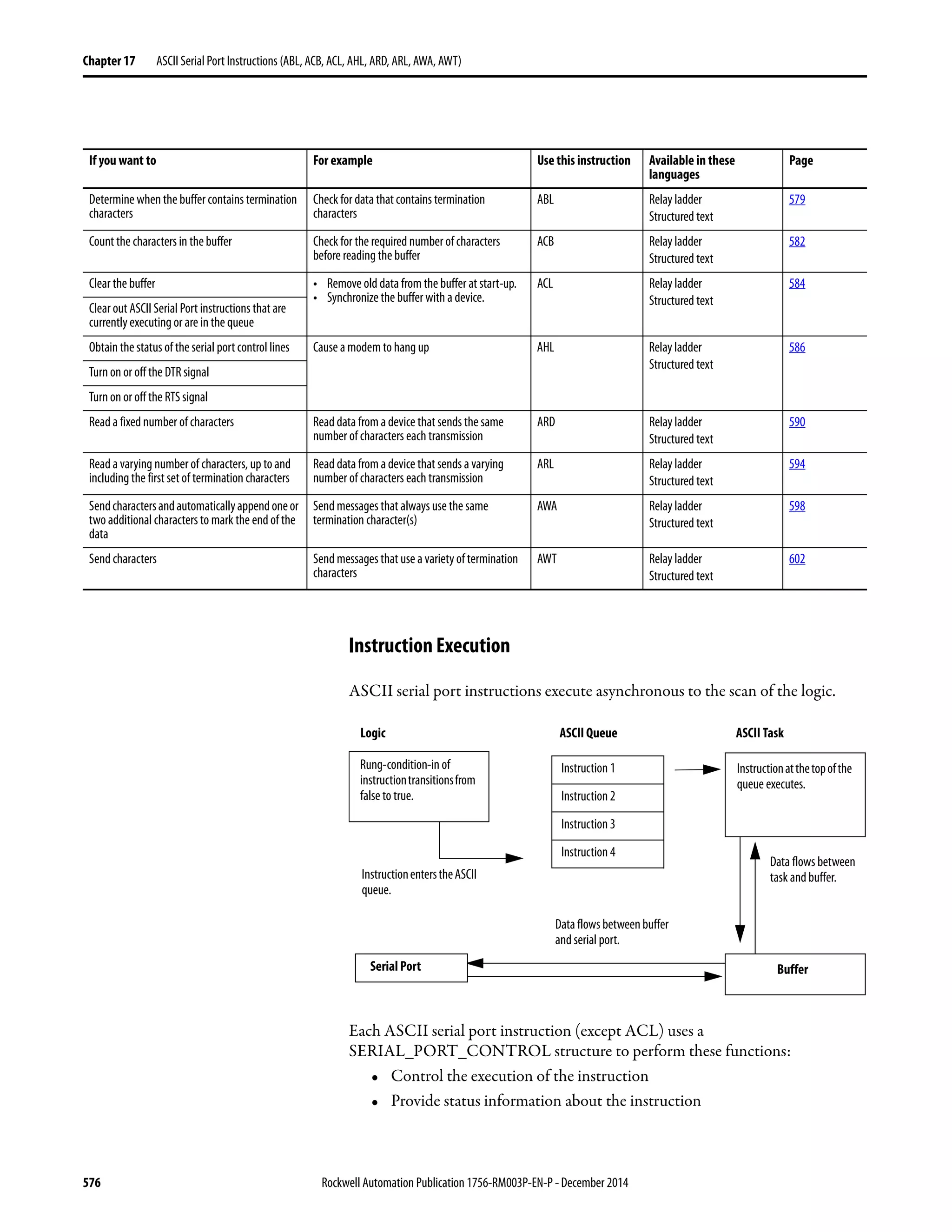


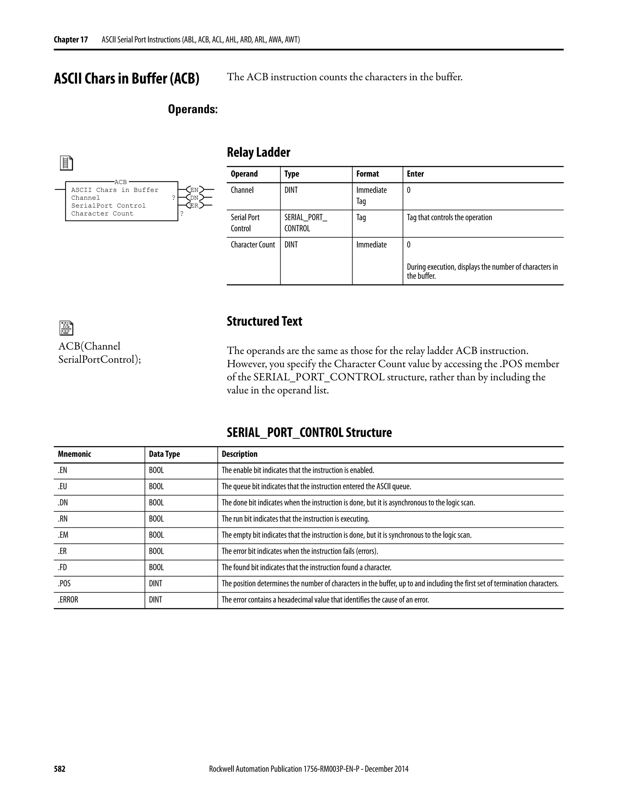

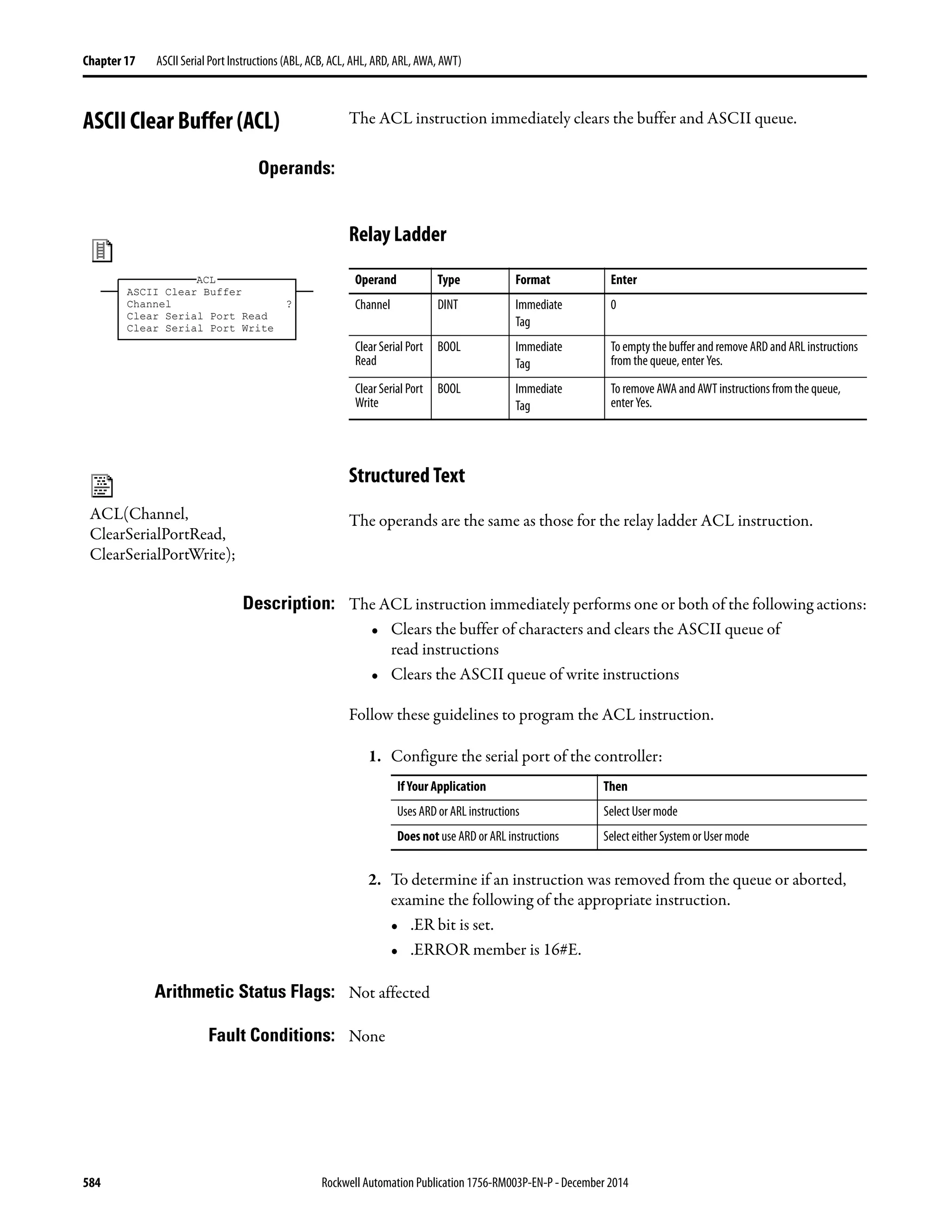
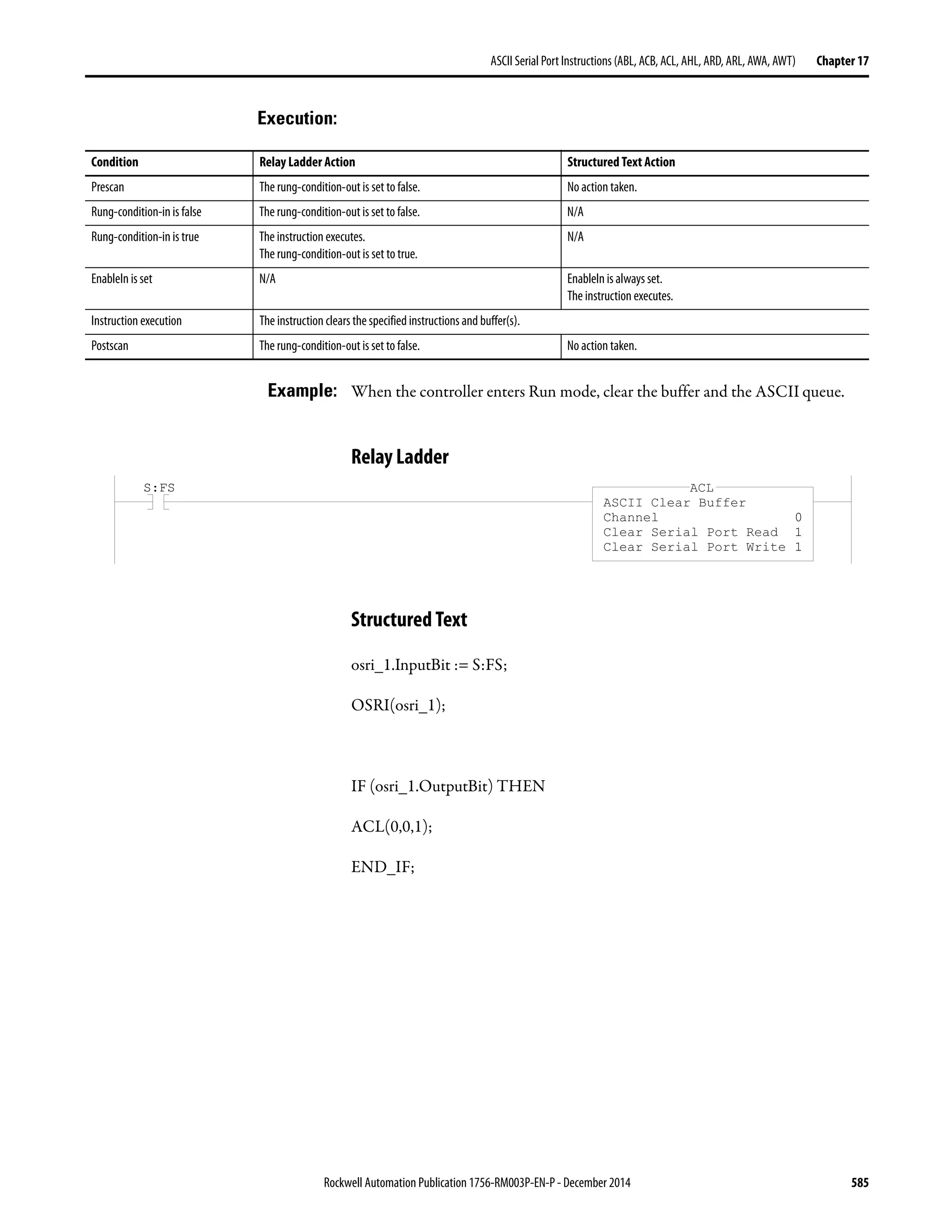

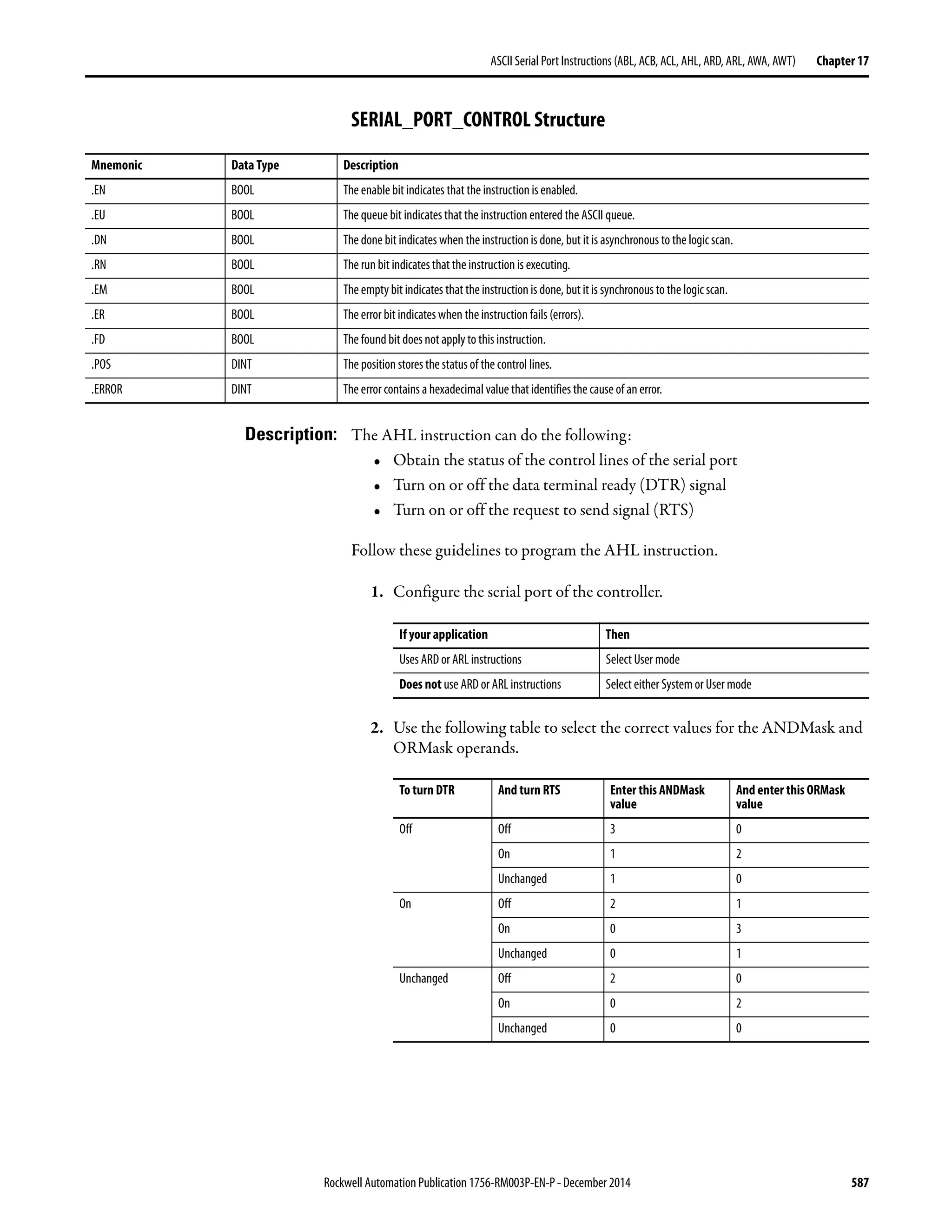


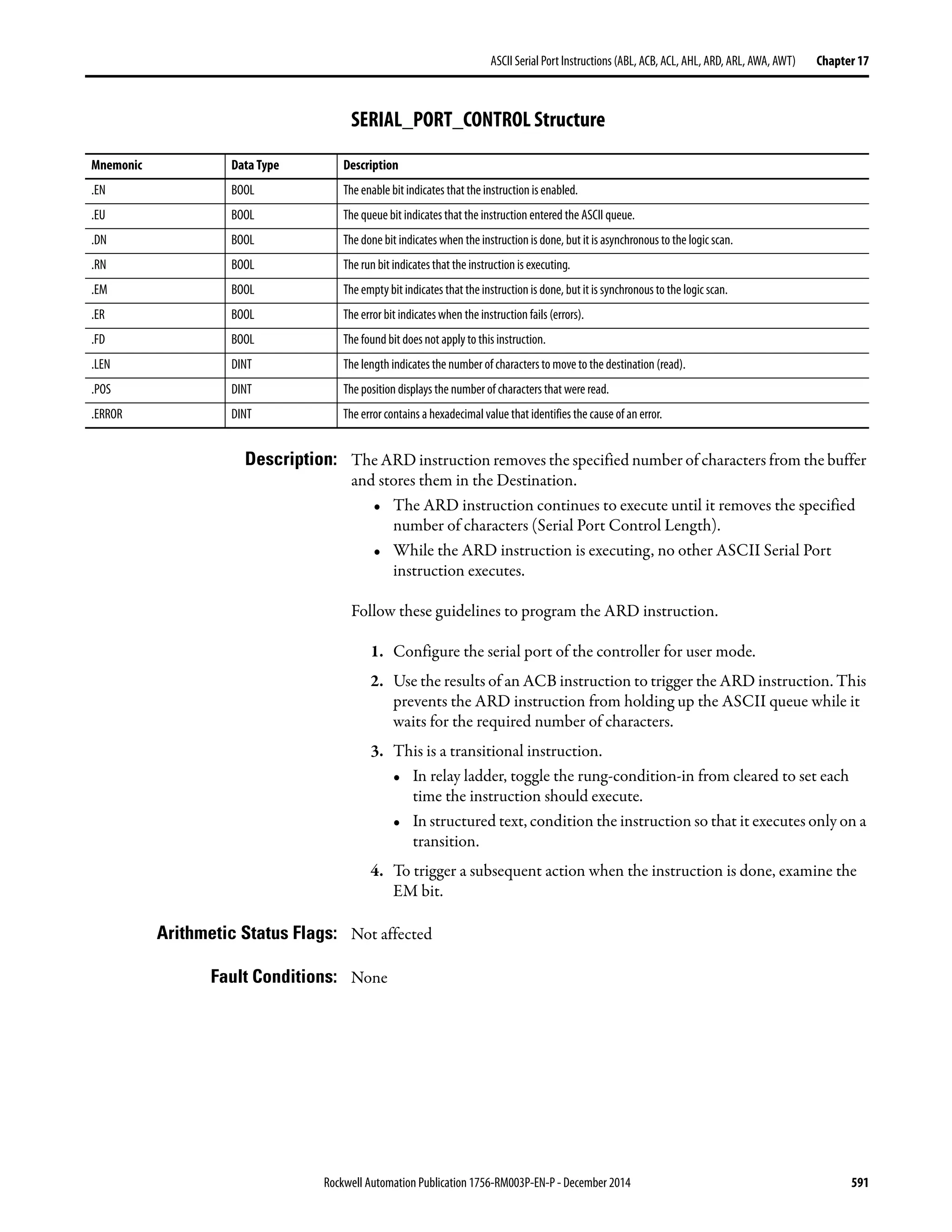


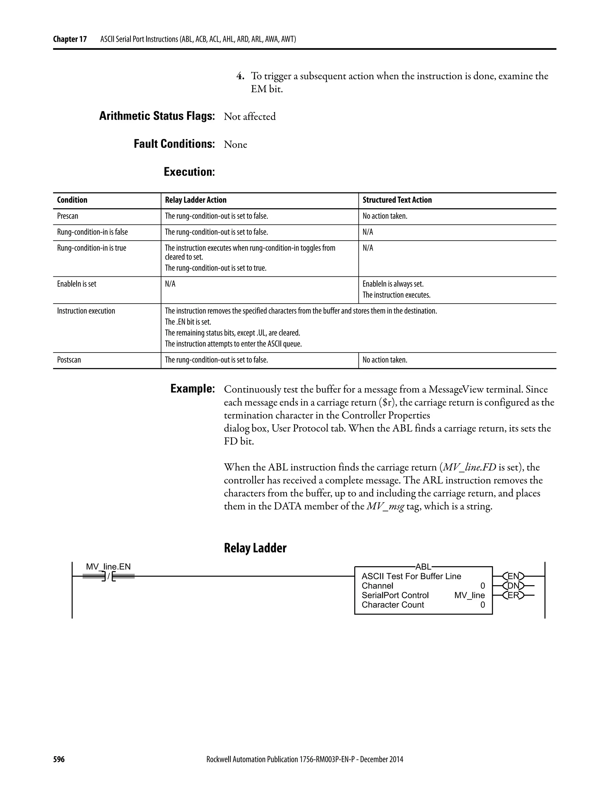
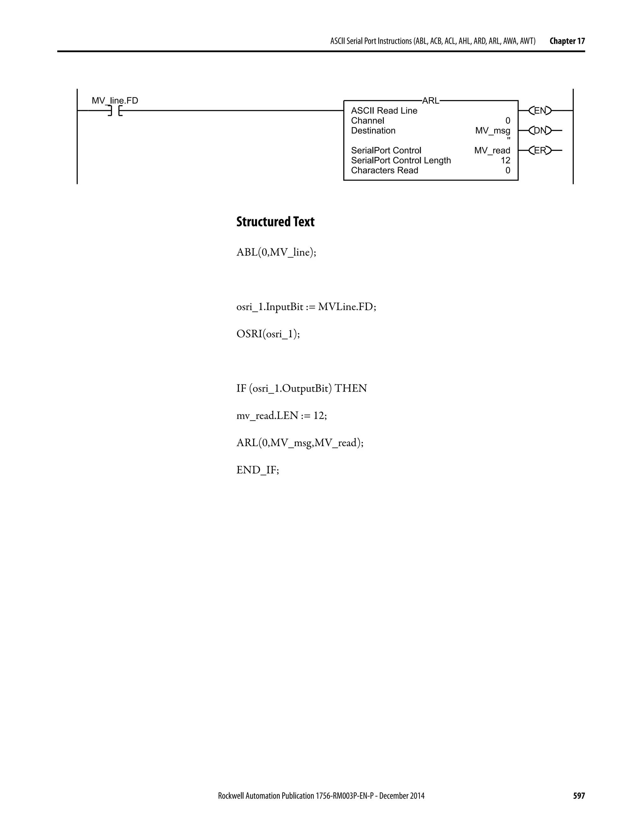


![600 Rockwell Automation Publication 1756-RM003P-EN-P - December 2014
Chapter 17 ASCII Serial Port Instructions (ABL, ACB, ACL, AHL, ARD, ARL, AWA, AWT)
Fault Conditions: None
Execution:
Example 1: When the temperature exceeds the high limit (temp_high is set), the AWA
instruction sends a message to a MessageView terminal that is connected to the
serial port of the controller. The message contains five characters from the DATA
member of the string[1] tag, which is a string. (The $14 counts as one character.
It is the hex code for the Ctrl-T character.) The instruction also sends (appends)
the characters defined in the controller properties. In this example, the AWA
instruction sends a carriage return ($0D), which marks the end of the message.
Relay Ladder
Structured Text
IF temp_high THEN
temp_high_write.LEN := 5;
AWA(0,string[1],temp_high_write);
temp_high := 0;
END_IF;
Condition Relay Ladder Action Structured Text Action
Prescan The rung-condition-out is set to false. No action taken.
Rung-condition-in is false The rung-condition-out is set to false. N/A
Rung-condition-in is true The instruction executes when rung-condition-in toggles from
cleared to set.
The rung-condition-out is set to true.
N/A
EnableIn is set N/A EnableIn is always set.
The instruction executes.
Instruction execution The instruction sends a specified number of characters and appends either one or two predefined characters.
The .EN bit is set.
The remaining status bits, except .UL, are cleared.
The instruction attempts to enter the ASCII queue.
Postscan The rung-condition-out is set to false. No action taken.
temp_high
EN
DN
ER
ASCII Write Append
Channel 0
Source string[1]
'$14251'
SerialPort Control temp_high_write
SerialPort Control Length 5
Characters Sent 6
AWA](https://image.slidesharecdn.com/1756-rm003-en-p-150617024022-lva1-app6892/75/1756-rm003-en-p-600-2048.jpg)


![604 Rockwell Automation Publication 1756-RM003P-EN-P - December 2014
Chapter 17 ASCII Serial Port Instructions (ABL, ACB, ACL, AHL, ARD, ARL, AWA, AWT)
Execution:
Example 1: When the temperature reaches the low limit (temp_low is set), the AWT
instruction sends a message to the MessageView terminal that is connected to the
serial port of the controller. The message contains nine characters from the
DATA member of the string[2] tag, which is a string. (The $14 counts as one
character. It is the hex code for the Ctrl-T character.) The last character is a
carriage return ($r), which marks the end of the message.
Relay Ladder
Structured Text
osri_1.InputBit := temp_low;
OSRI(osri_1);
IF (osri_1.OutputBit) THEN
temp_low_write.LEN := 9;
AWT(0,string[2],temp_low_write);
END_IF;
Condition Relay Ladder Action Structured Text Action
Prescan The rung-condition-out is set to false. No action taken.
Rung-condition-in is false The rung-condition-out is set to false. N/A
Rung-condition-in is true The instruction executes when rung-condition-in toggles from
cleared to set.
The rung-condition-out is set to true.
N/A
EnableIn is set N/A EnableIn is always set.
The instruction executes.
Instruction execution The instruction sends a specified number of characters.
The .EN bit is set.
The remaining status bits, except .UL, are cleared.
The instruction attempts to enter the ASCII queue.
Postscan The rung-condition-out is set to false. No action taken.
temp_low
EN
DN
ER
ASCII Write
Channel 0
Source string[2]
'$14222401$r'
SerialPort Control temp_low_write
SerialPort Control Length 9
Characters Sent 9
AWT](https://image.slidesharecdn.com/1756-rm003-en-p-150617024022-lva1-app6892/75/1756-rm003-en-p-604-2048.jpg)


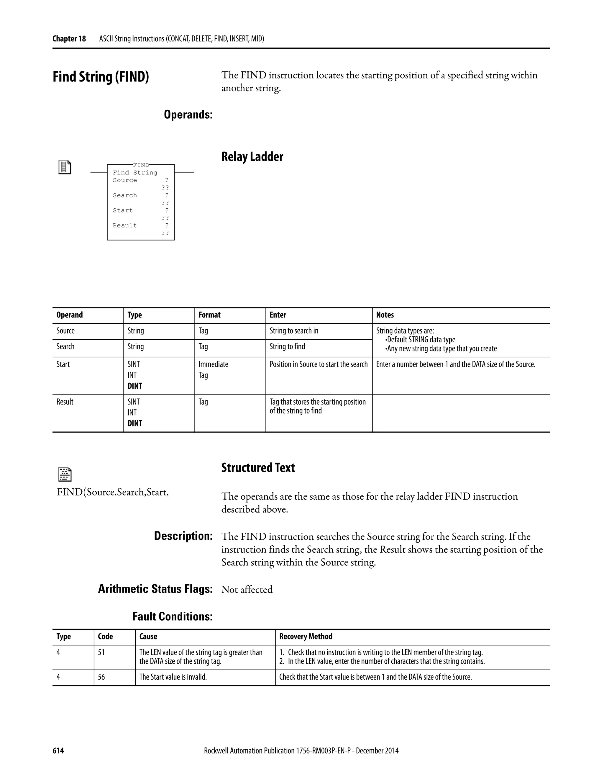
![Rockwell Automation Publication 1756-RM003P-EN-P - December 2014 615
ASCII String Instructions (CONCAT, DELETE, FIND, INSERT, MID) Chapter 18
Execution:
Example: A message from a MessageView terminal contains several pieces of information.
The backslash character [ ] separates each piece of information. To locate a piece
of information, the FIND instruction searches for the backslash character and
records its position in find_pos.
Relay Ladder
Structured Text
IF MV_read.EM THEN
FIND(MV_msg,find,1,find_pos);
MV_read.EM := 0;
END_IF;
Condition Relay Ladder Action Structured Text Action
Prescan The rung-condition-out is set to false. No action taken.
Rung-condition-in is false The rung-condition-out is set to false. N/A
Rung-condition-in is true The instruction executes.
The rung-condition-out is set to true.
N/A
EnableIn is set N/A EnableIn is always set.
The instruction executes.
Instruction execution The instruction searches for the specified characters.
Postscan The rung-condition-out is set to false. No action taken.
MV_read.EM
Find String
Source MV_msg
'$06324121$r'
Search find
''
Start 1
Result find_pos
5
FIND](https://image.slidesharecdn.com/1756-rm003-en-p-150617024022-lva1-app6892/75/1756-rm003-en-p-615-2048.jpg)


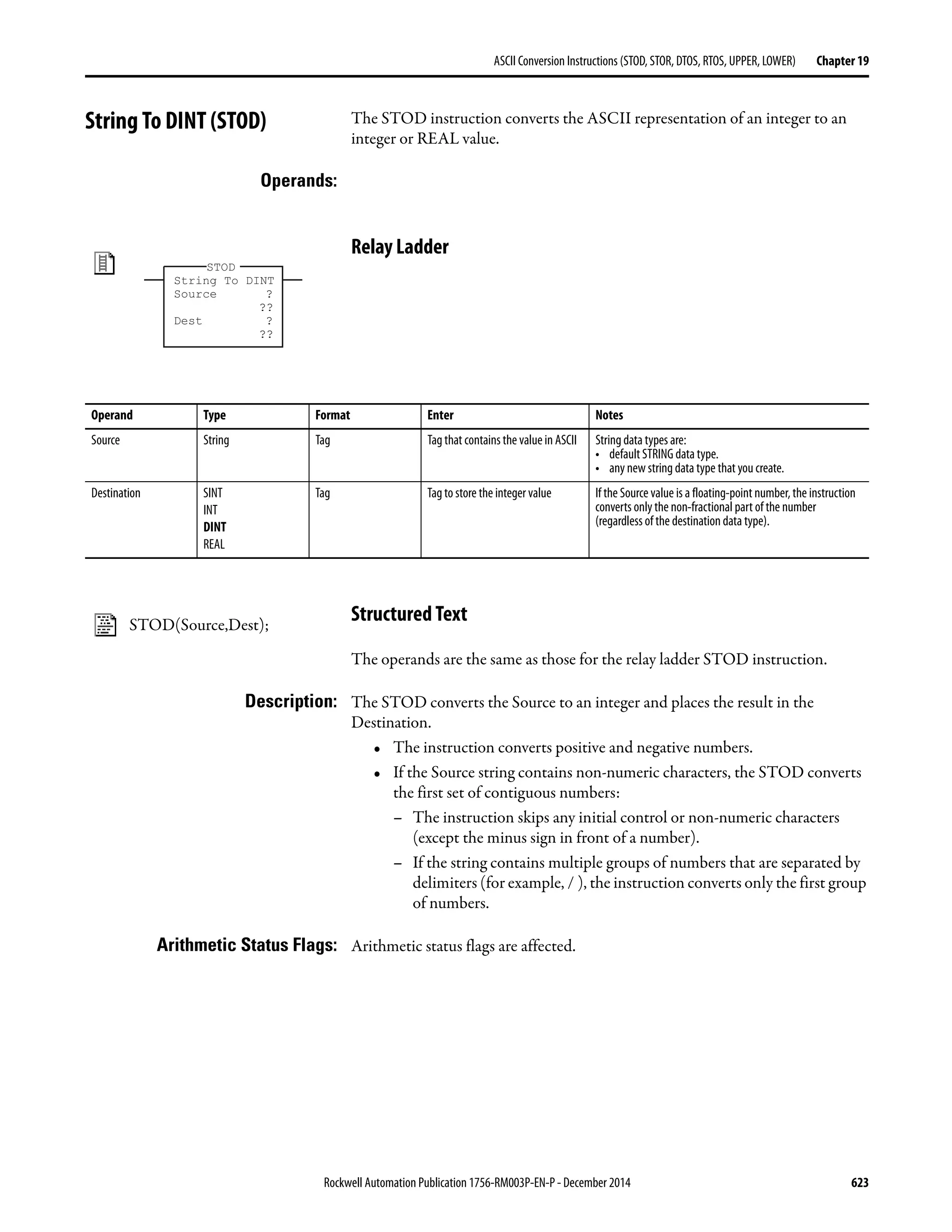
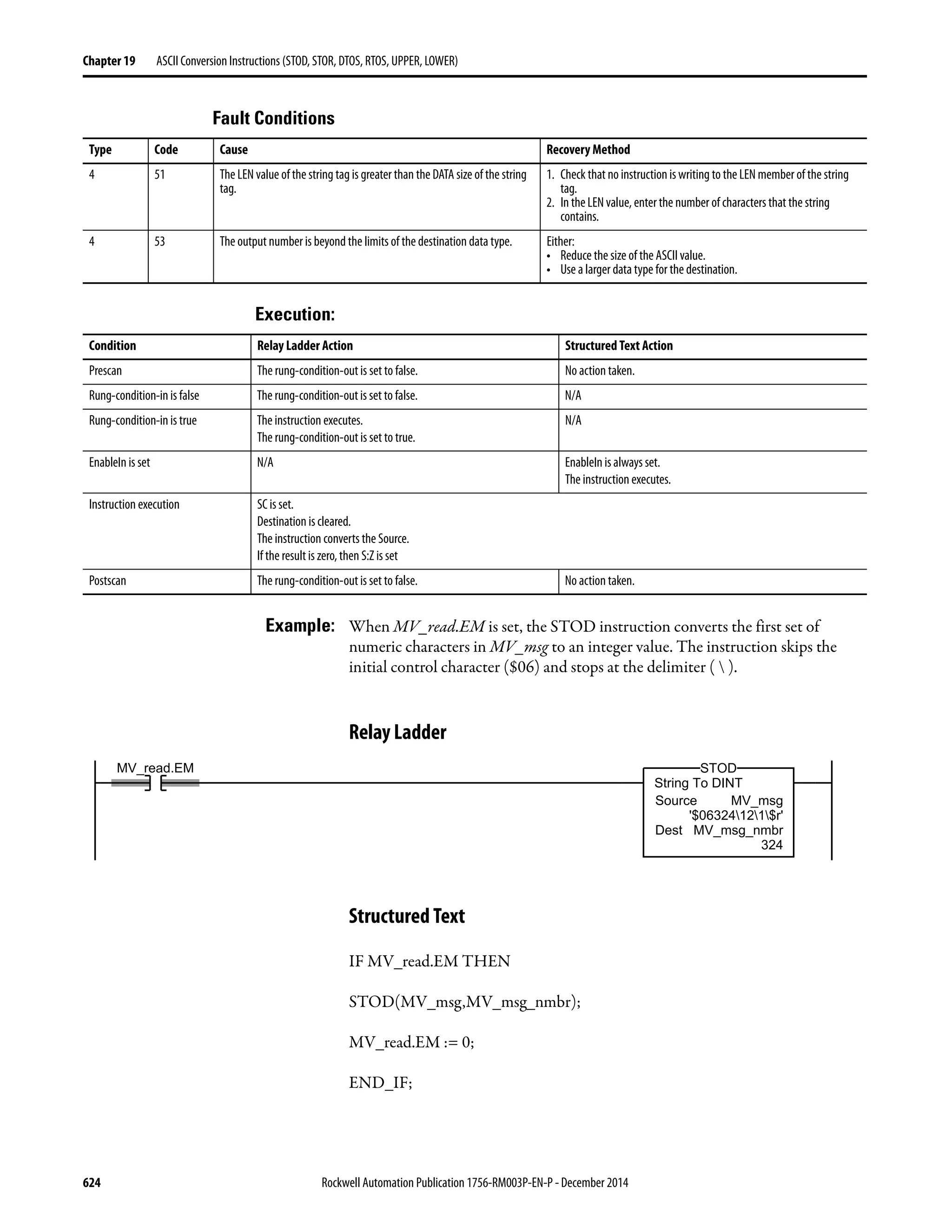
![Rockwell Automation Publication 1756-RM003P-EN-P - December 2014 625
ASCII Conversion Instructions (STOD, STOR, DTOS, RTOS, UPPER, LOWER) Chapter 19
String To REAL (STOR) The STOR instruction converts the ASCII representation of a floating-point
value to a REAL value.
Operands:
Relay Ladder Operands
Structured Text
The operands are the same as those for the relay ladder STOR instruction.
Description: The STOR converts the Source to a REAL value and places the result in the
Destination.
• The instruction converts positive and negative numbers.
• If the Source string contains non-numeric characters, the STOR converts
the first set of contiguous numbers, including the decimal point [ . ]:
– The instruction skips any initial control or non-numeric characters
(except the minus sign in front of a number).
– If the string contains multiple groups of numbers that are separated by
delimiters (for example, / ), the instruction converts only the first group
of numbers.
Arithmetic Status Flags: Arithmetic status flags are affected.
Fault Conditions:
String to Real
Source ?
??
Dest ?
??
STOR
Operand Type Format Enter Notes
Source String Tag Tag that contains the value in ASCII String data types are:
• Default STRING data type
• Any new string data type that you create
Destination REAL Tag Tag to store the REAL value
STOR(Source,Dest);
Type Code Cause Recovery Method
4 51 The LEN value of the string tag is greater than the DATA size of the string
tag.
1. Check that no instruction is writing to the LEN member of the string
tag.
2. In the LEN value, enter the number of characters that the string
contains.
4 53 The output number is beyond the limits of the destination data type. Either:
• Reduce the size of the ASCII value.
• Use a larger data type for the destination.](https://image.slidesharecdn.com/1756-rm003-en-p-150617024022-lva1-app6892/75/1756-rm003-en-p-625-2048.jpg)

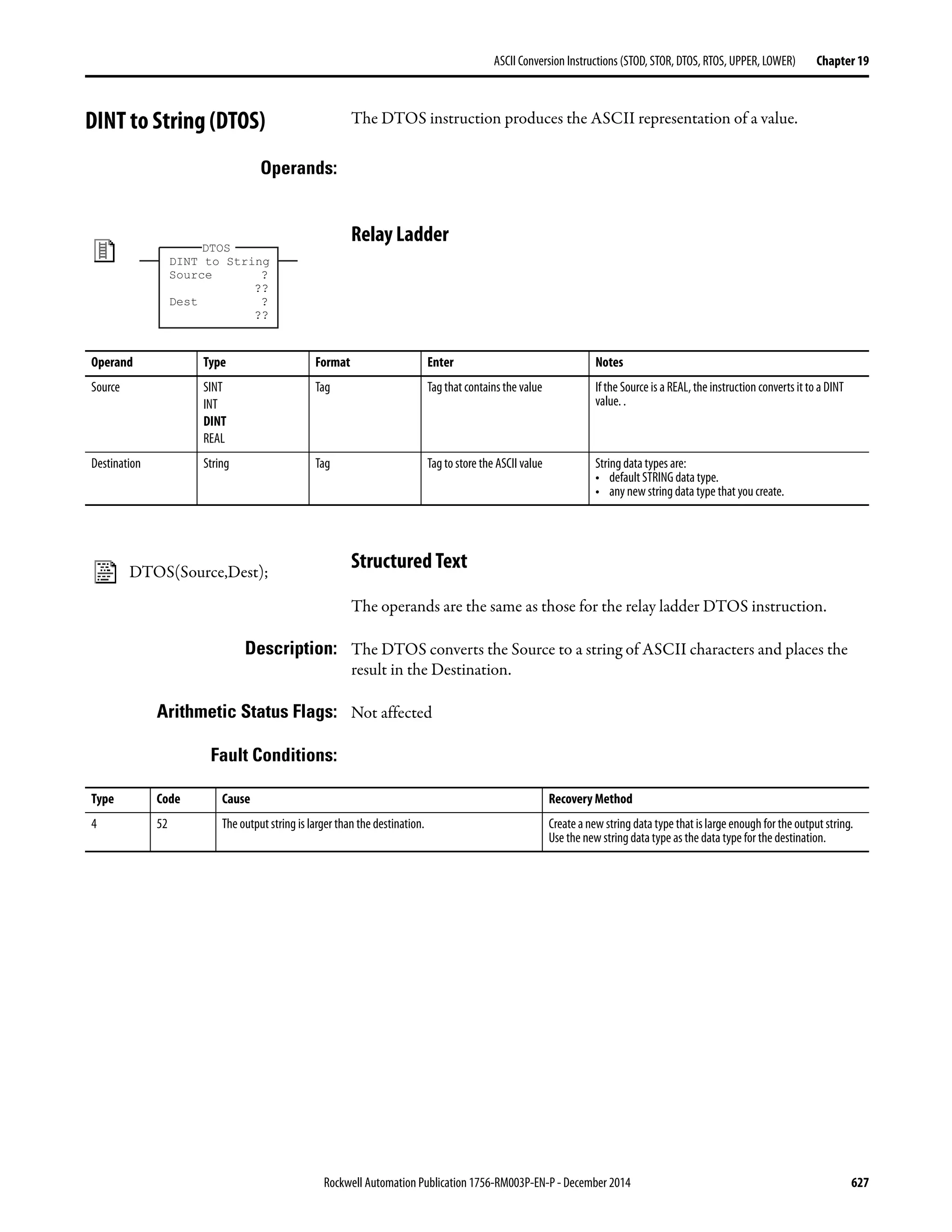
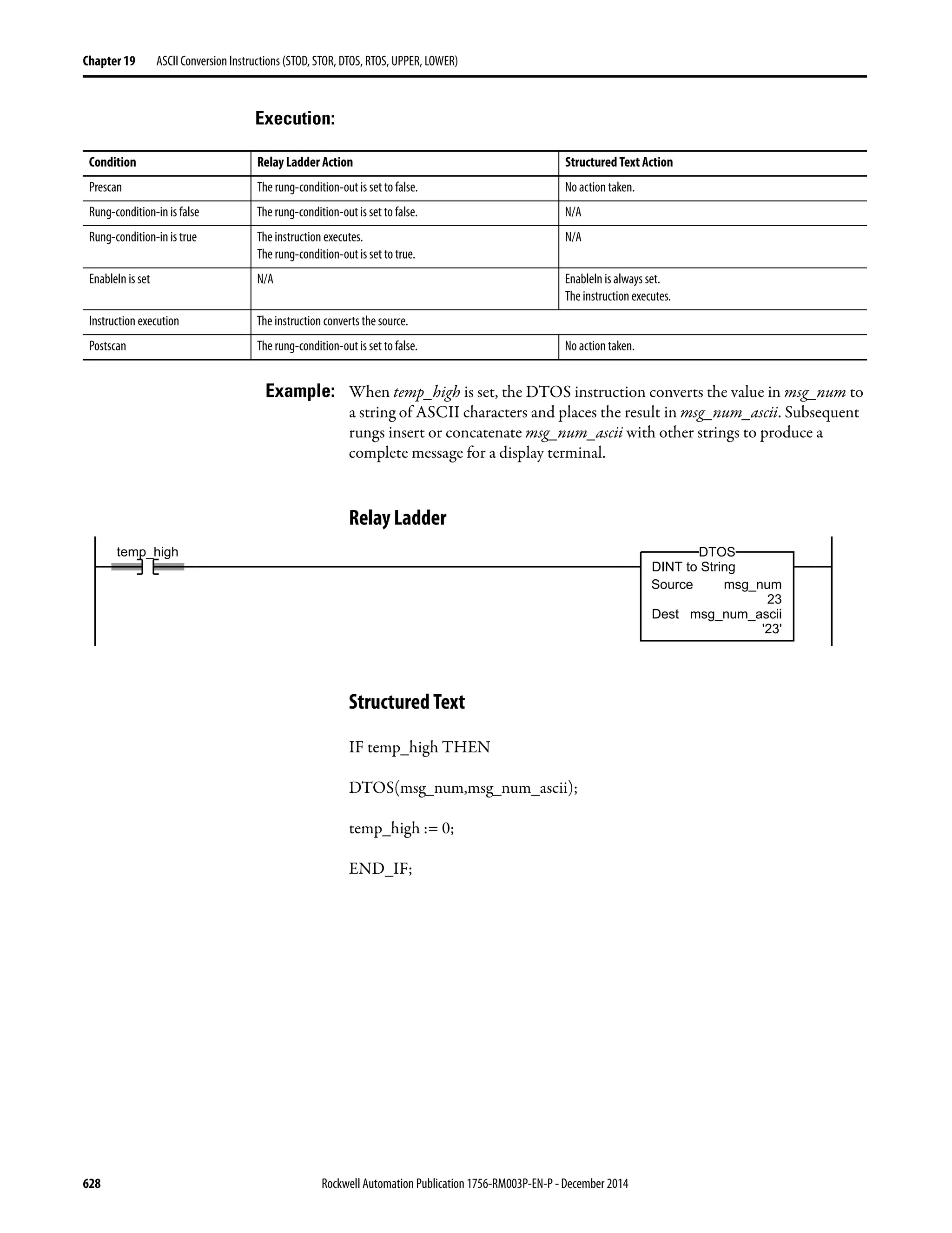


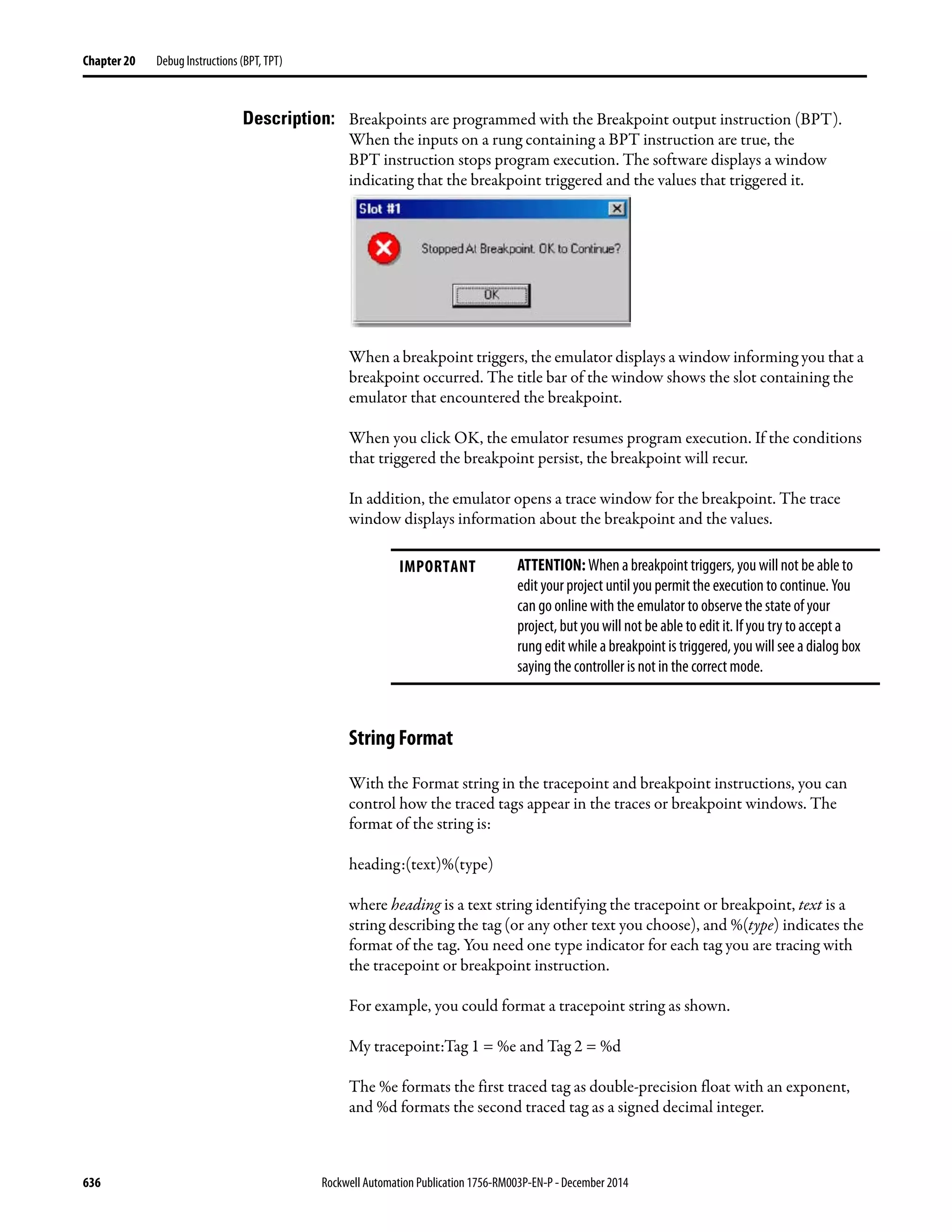


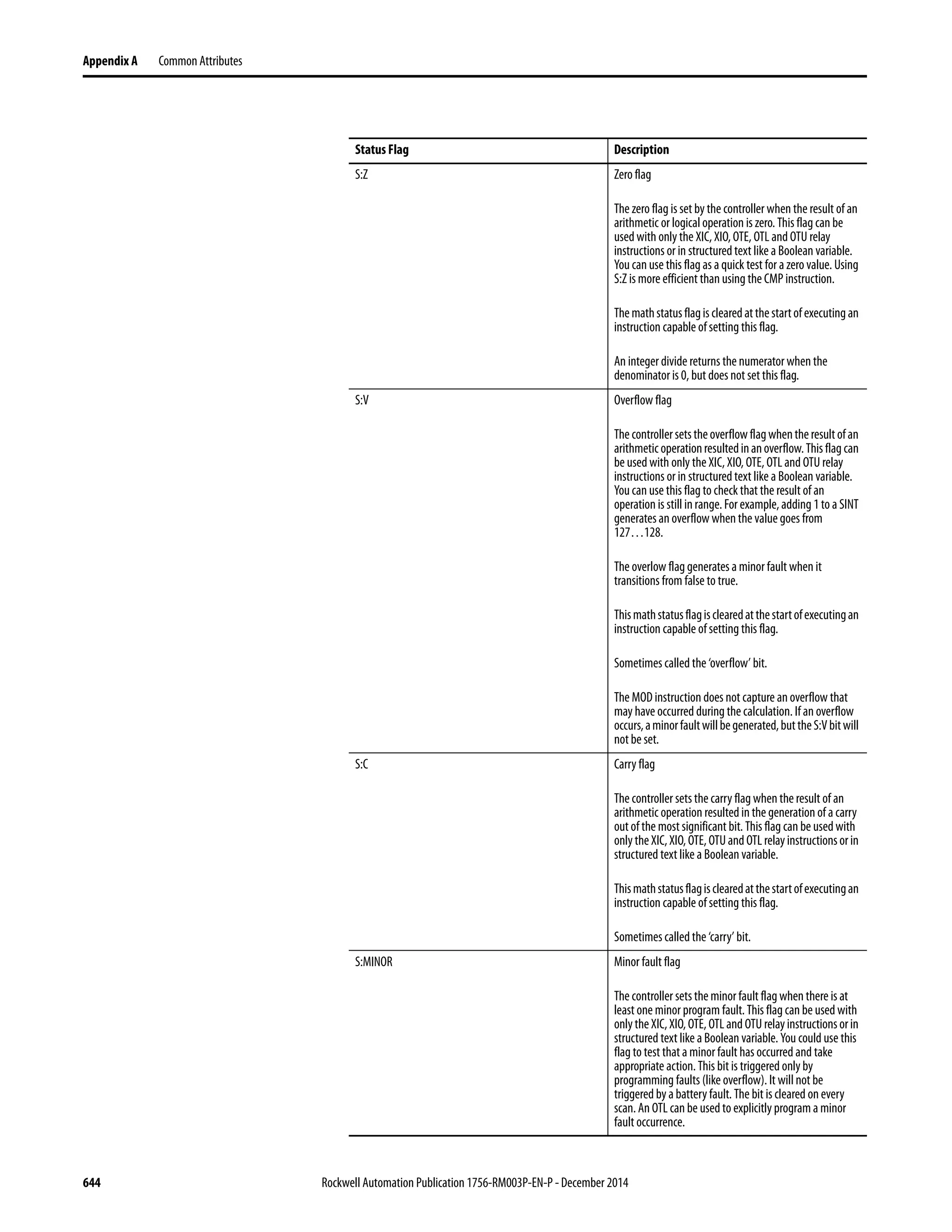
![Rockwell Automation Publication 1756-RM003P-EN-P - December 2014 645
Common Attributes Appendix A
Expressions in Array Subscripts
Expressions set status flags based on the results of arithmetic operations. If you
have an array subscript as an expression, both the expression and the instruction
could generate minor faults.
Under certain circumstances, the S:Z status flag may be set if the expression of an
array element evaluates to zero. In this example, Array[Element*3], 0 if
Element=0 the subscript [Element*3] evaluates to 0 and the S:Z bit will be set.
Immediate Values When you enter an immediate value (constant) in decimal format
(for example, -2, 3) the controller stores the value by using 32 bits. If you enter a
value in a radix other than decimal, such as binary or hexadecimal, and do not
specify all 32 bits, the controller places a zero in the bits that you do not specify
(zero-fill).
IMPORTANT Zero-filling of immediate values
If you enter The controller stores
-1 16#ffff ffff (-1)
16#ffff (-1) 16#0000 ffff (65535)
8#1234 (668) 16#0000 029c (668)
2#1010 (10) 16#0000 000a (10)](https://image.slidesharecdn.com/1756-rm003-en-p-150617024022-lva1-app6892/75/1756-rm003-en-p-645-2048.jpg)


![Rockwell Automation Publication 1756-RM003P-EN-P - December 2014 649
Common Attributes Appendix A
Data Types LINT Data Type Considerations
When using LINT data types, many limitations apply. A LINT data type cannot
be used in most instructions. Limitations are as follows:
• The LINT data type is not supported in Machine Edition. The LINT data
type is a 64-bit word; ME uses only 32-bit words.
• The LINT data type is not supported by HMIs.
• The LINT data type is not supported in most instructions.
When using LINT data types, consider the following descriptions when these
issues occur.
SINT or INT to DINT
For those instructions that convert SINT or INT values to DINT values, the
‘Operands’ sections in this manual identify the conversion method.
The following example shows the results of converting a value using sign-
extension and zero-fill.
TIP LINTs can only be used with Move and Copy instructions. They are used with
the CST/WallClock Time attribute, time synchronization and Add-On
Instructions.You cannot Add, Subtract, Multiply, or Divide this tag type.
How to Description
Move/copy two double-integer DINT values into one LINT Create a double integer array of two elements, total of 64
bits (that is, DINT[2], which can then be copied into one
long integer.
Correct Date/Time Display error Whenataghasanegativevalue,itcannotbedisplayedas
Date/Time. In the tag editor, check whether the value is
negative bychanging the style of thetag from Date/Time
to Binary. When the most significant bit (leftmost one) is
1,thevalueisnegativeandthereforecannotbedisplayed
as a Date or Time.
This conversion method Converts data by placing
Sign-extension The value of the leftmost bit (the sign of thevalue) into eachbitposition to
the left of the existing bits until there are 32 bits.
Zero-fill Zeroes to the left of the existing bits until there are 32 bits.
This value 2#1111_1111_1111_1111 (-1)
Converts to this value by
sign-extension
2#1111_1111_1111_1111_1111_1111_1111_1111 (-1)
Converts to this value by
zero-fill
2#0000_0000_0000_0000_1111_1111_1111_1111 (65535)](https://image.slidesharecdn.com/1756-rm003-en-p-150617024022-lva1-app6892/75/1756-rm003-en-p-649-2048.jpg)
![650 Rockwell Automation Publication 1756-RM003P-EN-P - December 2014
Appendix A Common Attributes
Because immediate values are always zero-filled, the conversion of a SINT or
INT value may produce unexpected results. In the following example, the
comparison is false because Source A, an INT, converts by sign-extension; while
Source B, an immediate value, is zero-filled.
If you use a SINT or INT tag and an immediate value in an instruction that
converts data by sign-extension, use one of these methods to handle immediate
values.
• Specify any immediate value in the decimal radix.
• If you are entering the value in a radix other than decimal, specify all
32 bits of the immediate value. To do so, enter the value of the leftmost bit
into each bit position to its left until there are 32 bits.
• Create a tag for each operand and use the same data type throughout the
instruction. To assign a constant value, either:
– Enter it into one of the tags.
– Add a MOV instruction that moves the value into one of the tags.
• Use a MEQ instruction to check only the required bits.
The following examples show two ways to mix an immediate value with an INT
tag. Both examples check the bits of a 1771 I/O module to determine if all the
bits are on. Since the input data word of a 1771 I/O module is an INT tag, it is
easiest to use a 16-bit constant value.
IMPORTANT Mixing an INT tag with an immediate value
ATTENTION: Since remote_rack_1:I.Data[0] is an INT tag, the value to
check it against is also entered as an INT tag.
adder Logic Listing - Total number of rungs: 3
Equal
Source A remote_rack_1:I.Data[0]
2#1111_1111_1111_1111
Source B2#1111_1111_1111_1111
EQU
42093
Equal
Source Aremote_rack_1:I.Data[0]
2#1111_1111_1111_1111
Source B int_0
2#1111_1111_1111_1111
EQU
42093](https://image.slidesharecdn.com/1756-rm003-en-p-150617024022-lva1-app6892/75/1756-rm003-en-p-650-2048.jpg)
![Rockwell Automation Publication 1756-RM003P-EN-P - December 2014 651
Common Attributes Appendix A
Integer to REAL
The controller stores REAL values in IEEE single-precision, floating-point
number format. It uses one bit for the sign of the value, 23 bits for the base value,
and eight bits for the exponent (32 bits total). If you mix an integer tag (SINT,
INT, or DINT) and a REAL tag as inputs in the same instruction, the controller
converts the integer value to a REAL value before the instruction executes.
• A SINT or INT value always converts to the same REAL value.
• A DINT value may not convert to the same REAL value:
– A REAL value uses up to 24 bits for the base value (23 stored bits plus a
‘hidden’ bit).
– A DINT value uses up to 32 bits for the value (one for the sign and 31
for the value).
– If the DINT value requires more than 24 significant bits, it may not
convert to the same REAL value. If it will not, the controller rounds to
the nearest REAL value by using 24 significant bits.
DINT to SINT or INT
To convert a DINT value to a SINT or INT value, the controller truncates the
upper portion of the DINT and sets the overflow status flag, if necessary. The
following example shows the result of a DINT to SINT or INT conversion.
IMPORTANT Mixing an INT tag with an immediate value
Since remote_rack_1:I.Data[0] is an INT tag, the value to check it against
first moves into int_0, also an INT tag. The EQU instruction then compares
both tags.
IMPORTANT Conversion of a DINT to an INT and a SINT
2#1111_1111_1111_1111
Move
Source2#1111_1111_1111_1111
Dest int_0
2#1111_1111_1111_1111
MOV
Equal
Source Aremote_rack_1:I.Data[0]
2#1111_1111_1111_1111
Source B int_0
2#1111_1111_1111_1111
EQU
42093
This DINT value Converts to this smaller value
16#0001_0081 (65,665) INT: 16#0081 (129)
SINT: 16#81 (-127)](https://image.slidesharecdn.com/1756-rm003-en-p-150617024022-lva1-app6892/75/1756-rm003-en-p-651-2048.jpg)
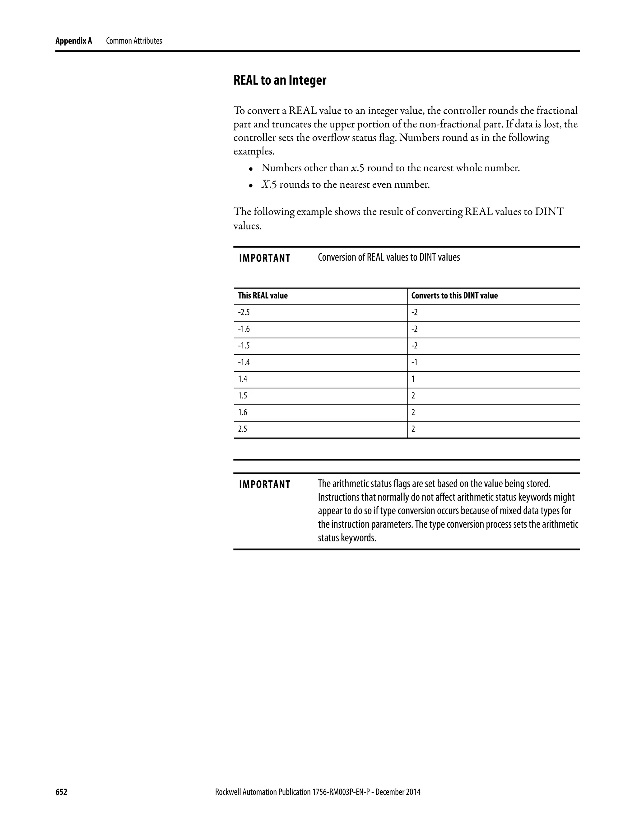

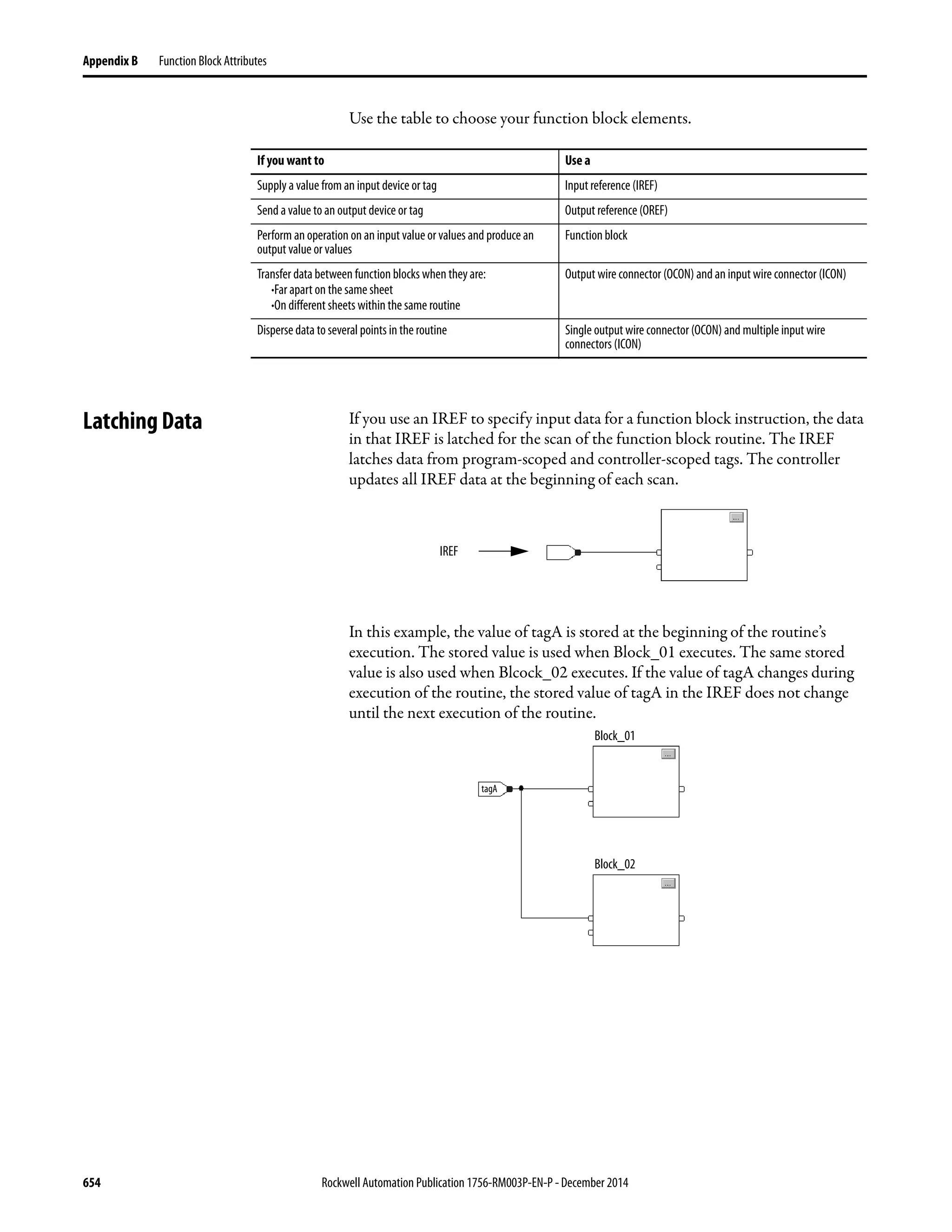


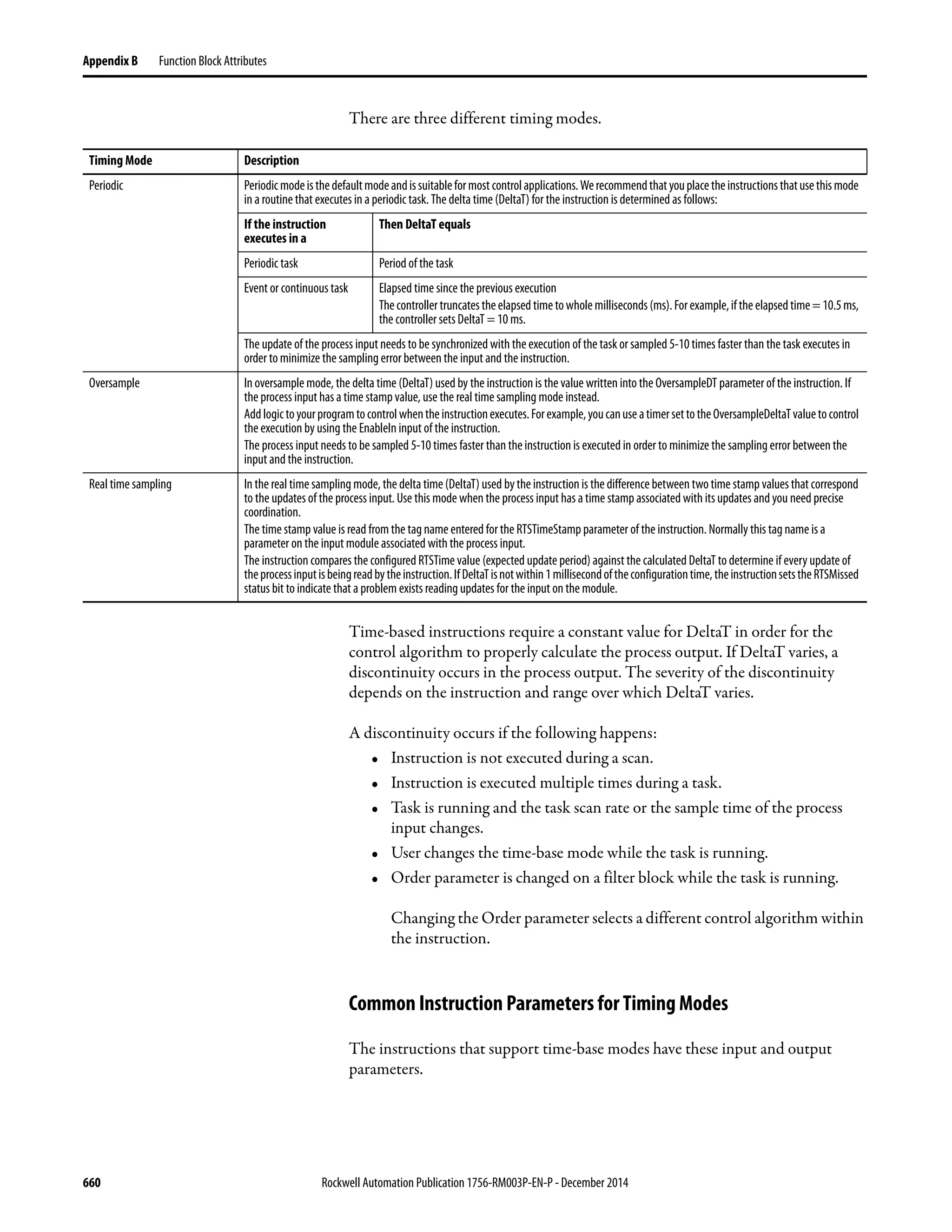


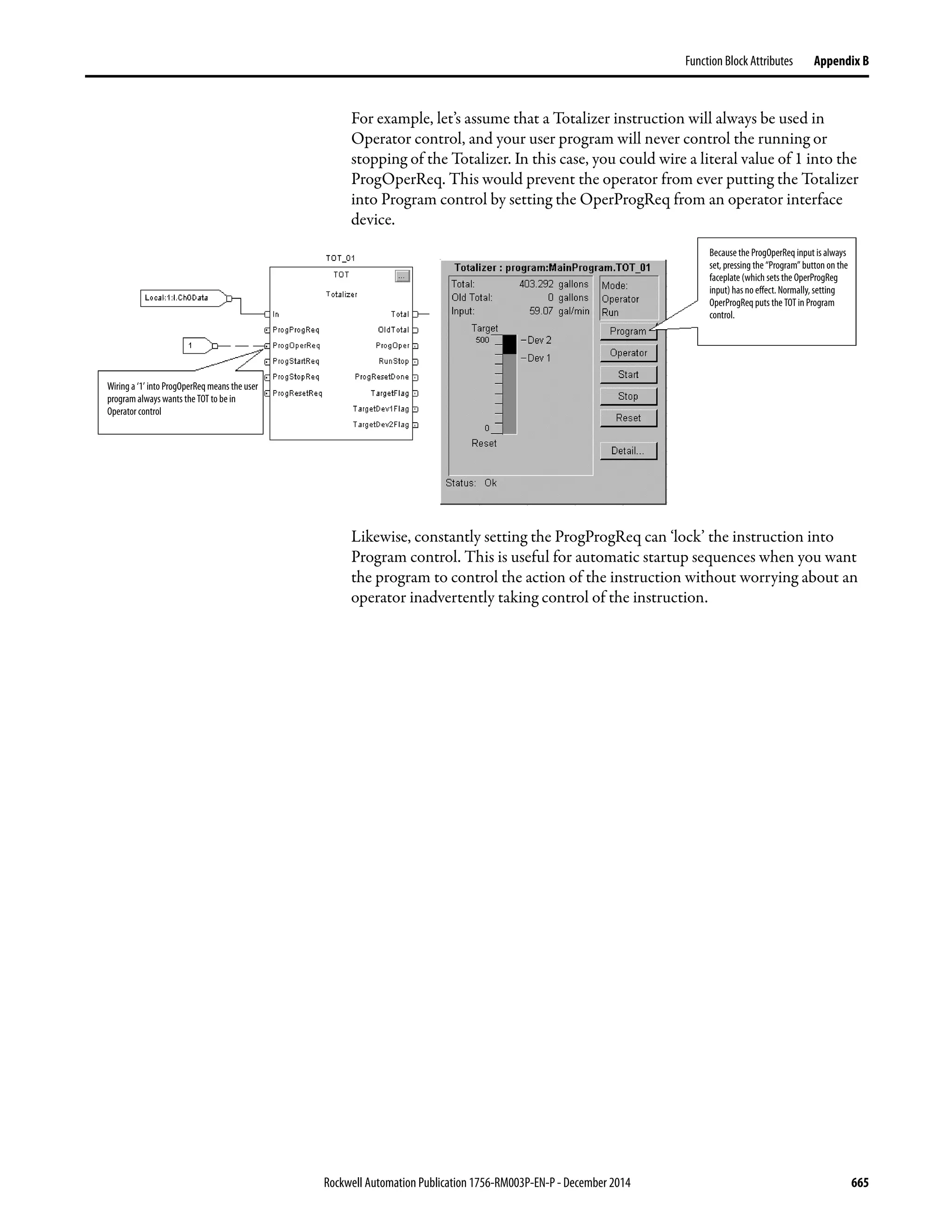

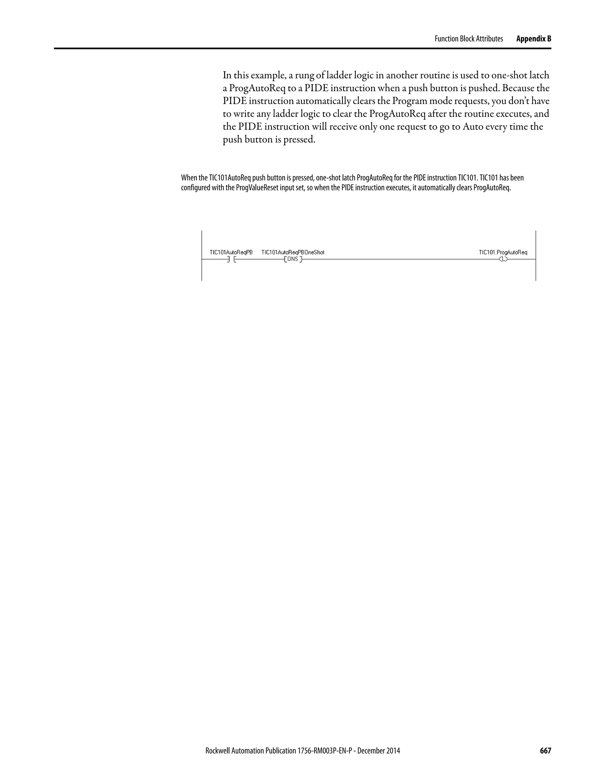

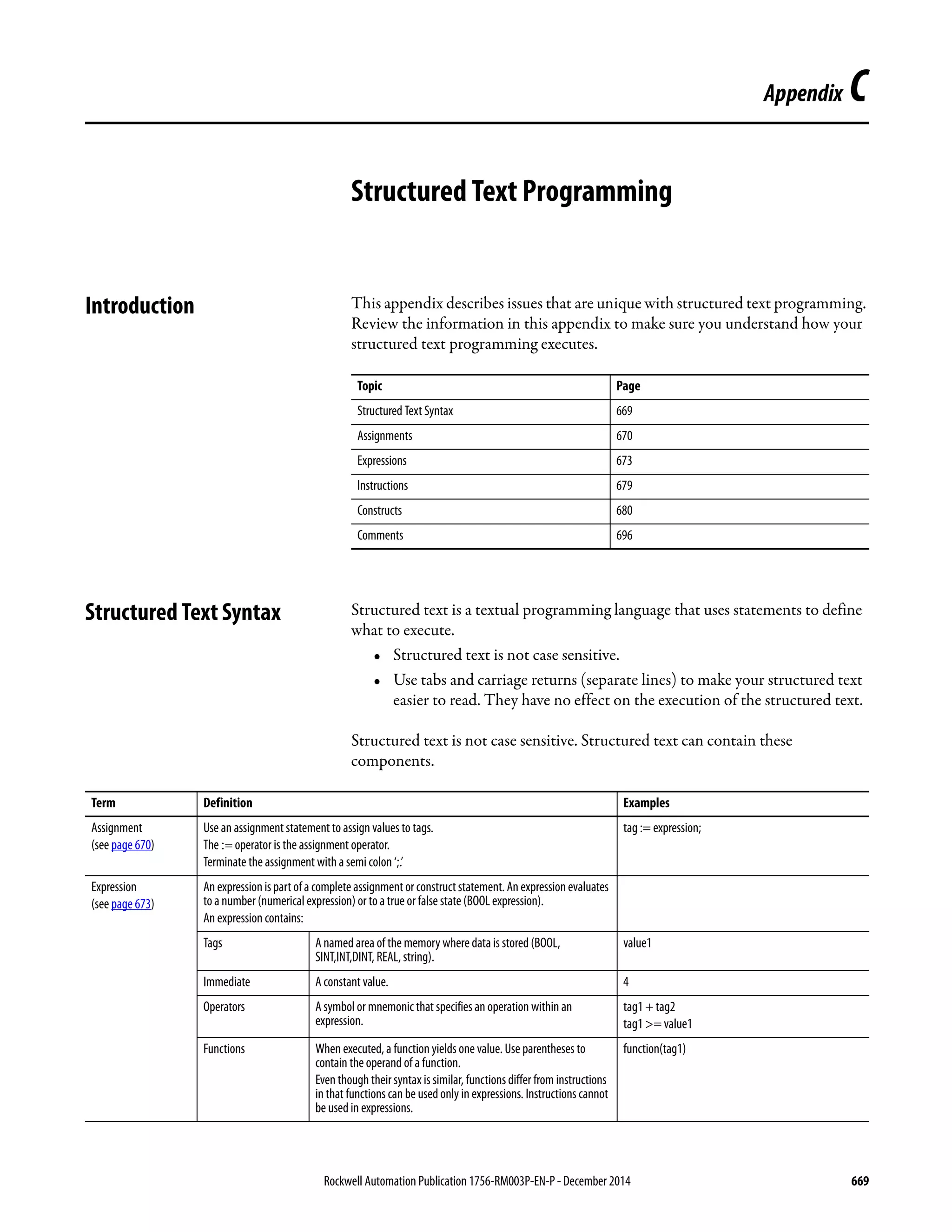

![Rockwell Automation Publication 1756-RM003P-EN-P - December 2014 671
Structured Text Programming Appendix C
Specify a Non-retentive Assignment
The non-retentive assignment is different from the regular assignment described
above in that the tag in a non-retentive assignment is reset to zero each time the
controller does the following:
• Enters the RUN mode.
• Leaves the step of an SFC if you configure the SFC for Automatic reset.
(This applies only if you embed the assignment in the action of the step or
use the action to call a structured text routine via a JSR instruction.)
A non-retentive assignment has this syntax:
tag [:=] expression ;
where:
Component Description
Tag Represents the tag that is getting the new value
The tag must be a BOOL, SINT, INT, DINT, or REAL
[:=] Is the non-retentive assignmentsymbol
Expression Represents the new value to assign to the tag
If tag is this data type Use this type of expression
BOOL BOOL expression
SINT
INT
DINT
REAL
Numeric expression
; Ends the assignment](https://image.slidesharecdn.com/1756-rm003-en-p-150617024022-lva1-app6892/75/1756-rm003-en-p-671-2048.jpg)
![672 Rockwell Automation Publication 1756-RM003P-EN-P - December 2014
Appendix C Structured Text Programming
Assign an ASCII Character to a String
Use the assignment operator to assign an ASCII character to an element of the
DATA member of a string tag. To assign a character, specify the value of the
character or specify the tag name, DATA member, and element of the character.
The table shows some examples.
To add or insert a string of characters to a string tag, use either of these ASCII
string instructions.
This Is Okay This Is Not Okay
string1.DATA[0]:= 65; string1.DATA[0] := A;
string1.DATA[0]:= string2.DATA[0]; string1 := string2;
To Use this instruction
Add characters to the end of a string CONCAT
Insert characters into a string INSERT](https://image.slidesharecdn.com/1756-rm003-en-p-150617024022-lva1-app6892/75/1756-rm003-en-p-672-2048.jpg)
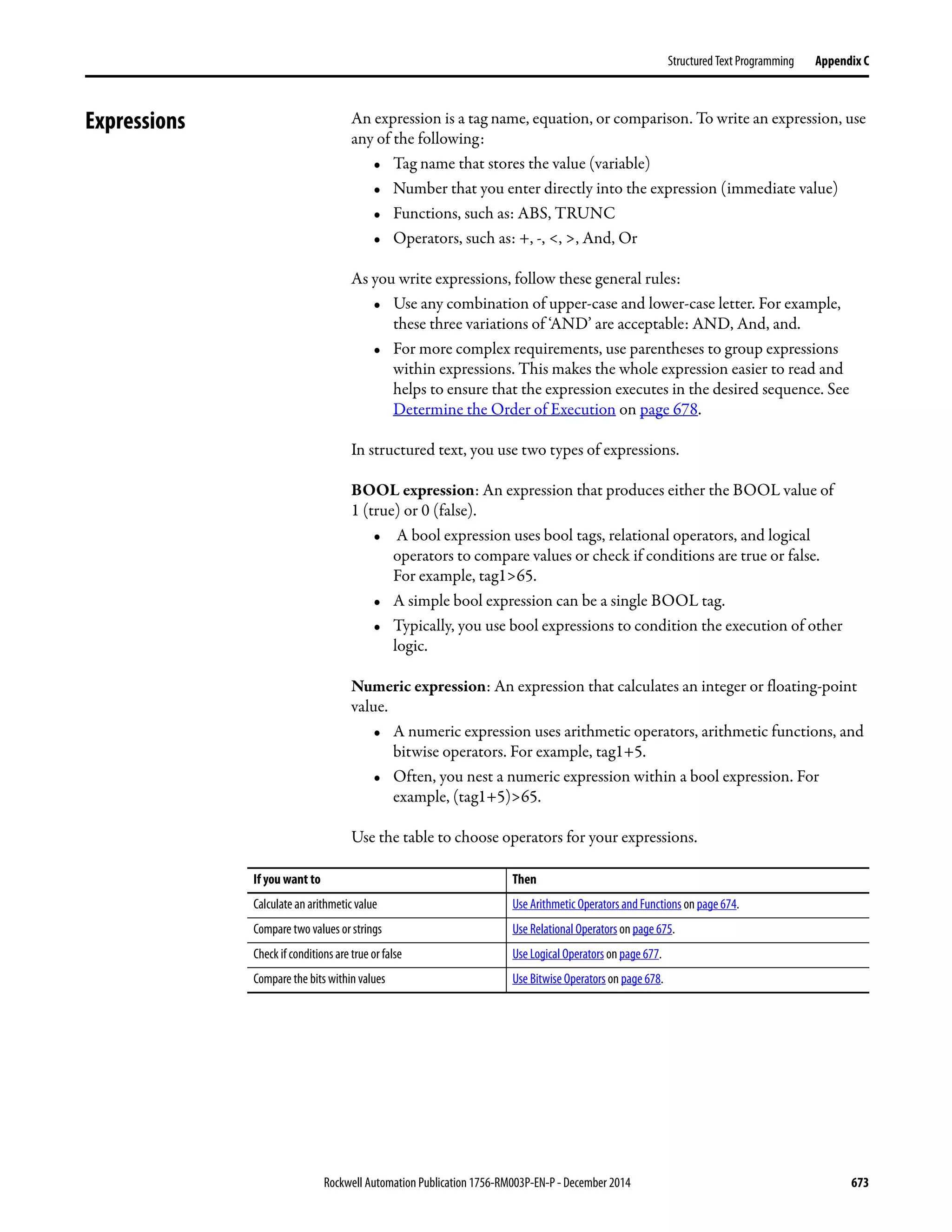

![Rockwell Automation Publication 1756-RM003P-EN-P - December 2014 675
Structured Text Programming Appendix C
Use Relational Operators
Relational operators compare two values or strings to provide a true or false
result. The result of a relational operation is a BOOL value.
Use these relational operators.
The table shows some examples.
If the comparison is The result is
True 1
False 0
For this comparison Use this operator Optimal data type
Equal = DINT, REAL, string
Less than < DINT, REAL, string
Less than or equal <= DINT, REAL, string
Greater than > DINT, REAL, string
Greater than or equal >= DINT, REAL, string
Not equal <> DINT, REAL, string
Use this format Example
For this situation Write
value1operatorvalue2 If tempisaDINT tag andyourspecificationsays:‘Iftempisless
than 100⋅ then…’
IF temp<100 THEN...
stringtag1operatorstringtag2 If bar_code and dest are string tags and your specification
says: ‘If bar_code equals dest then…’
IF bar_code=dest THEN...
char1operatorchar2
To enter an ASCII character directly into the expression,
enter the decimal value of the character.
If bar_code is a string tag and your specification says: ‘If
bar_code.DATA[0] equals ’A’ then…’
IF bar_code.DATA[0]=65 THEN...
bool_tag := bool_expressions If countand lengthareDINTtags, doneis a BOOL tag, and your
specification says: ‘If count is greater than or equal to length,
you aredone counting.’
Done := (count >= length);](https://image.slidesharecdn.com/1756-rm003-en-p-150617024022-lva1-app6892/75/1756-rm003-en-p-675-2048.jpg)


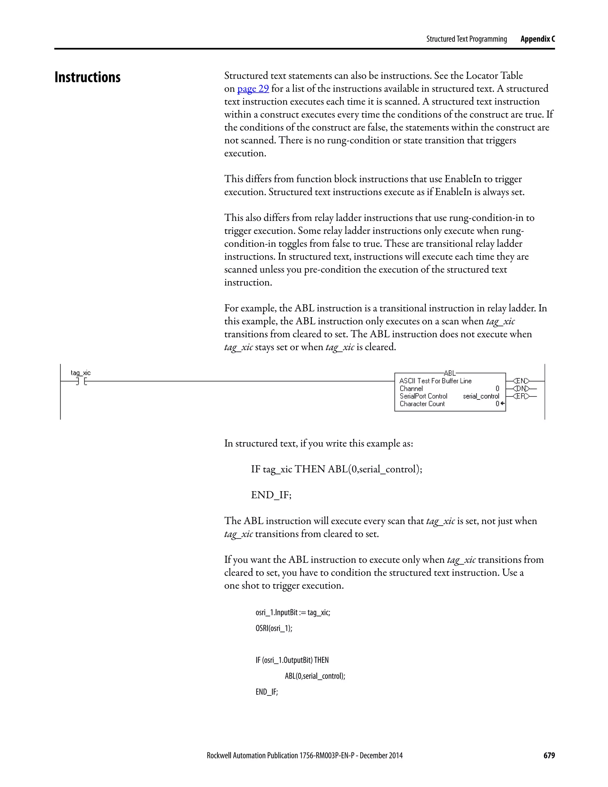


![682 Rockwell Automation Publication 1756-RM003P-EN-P - December 2014
Appendix C Structured Text Programming
The table summarizes different combinations of IF, THEN, ELSIF,
and ELSE.
Arithmetic Status Flags Not affected
Fault Conditions: None
Example 1: IF…THEN
Example 2: IF…THEN…ELSE
If you want to And Use this construct
Do something if or when conditions are true Do nothing if conditions are false IF…THEN
Do something else if conditions are false IF…THEN…ELSE
Choose from alternative statements (or groups of
statements) based on input conditions
Do nothing if conditions are false IF…THEN…ELSIF
Assign default statements if all conditions are false IF…THEN…ELSIF…ELSE
If you want this Enter this structured text
IF rejects > 3 then IF rejects > 3 THEN
conveyor = off (0) conveyor := 0;
alarm = on (1) alarm := 1;
END_IF;
If you want this Enter this structured text
If conveyor direction contact = forward (1) then IF conveyor_direction THEN
light =off light := 0;
Otherwise light = on ELSE
light [:=] 1;
END_IF;](https://image.slidesharecdn.com/1756-rm003-en-p-150617024022-lva1-app6892/75/1756-rm003-en-p-682-2048.jpg)
![Rockwell Automation Publication 1756-RM003P-EN-P - December 2014 683
Structured Text Programming Appendix C
The [:=] tells the controller to clear light whenever the controller does the
following:
• Enters the RUN mode.
• Leaves the step of an SFC if you configure the SFC for Automatic reset.
(This applies only if you embed the assignment in the action of the step or
use the action to call a structured text routine via a JSR instruction.)
Example 3: IF…THEN…ELSIF
The [:=] tells the controller to clear Sugar.Inlet whenever the controller does the
following:
• Enters the RUN mode.
• Leaves the step of an SFC if you configure the SFC for Automatic reset.
(This applies only if you embed the assignment in the action of the step or
use the action to call a structured text routine via a JSR instruction.)
Example 4: IF…THEN…ELSIF…ELSE
If you want this Enter this structured text
If sugar low limit switch = low (on) and sugar high limit switch = not high
(on) then
IF Sugar.Low & Sugar.High THEN
inlet valve = open (on) Sugar.Inlet [:=] 1;
Until sugar high limit switch = high (off) ELSIF NOT(Sugar.High) THEN
Sugar.Inlet := 0;
END_IF;
If you want this Enter this structured text
If tank temperature > 100 IF tank.temp > 200 THEN
then pump = slow pump.fast :=1; pump.slow :=0; pump.off :=0;
If tank temperature > 200 ELSIF tank.temp > 100 THEN
then pump = fast pump.fast :=0; pump.slow :=1; pump.off :=0;
Otherwise pump = off ELSE
pump.fast :=0; pump.slow :=0; pump.off :=1;
END_IF;](https://image.slidesharecdn.com/1756-rm003-en-p-150617024022-lva1-app6892/75/1756-rm003-en-p-683-2048.jpg)


![686 Rockwell Automation Publication 1756-RM003P-EN-P - December 2014
Appendix C Structured Text Programming
Example
The [:=] tells the controller to also clear the outlet tags whenever the controller
does the following:
• Enters the RUN mode.
• Leaves the step of an SFC if you configure the SFC for Automatic reset.
(This applies only if you embed the assignment in the action of the step or
use the action to call a structured text routine via a JSR instruction.)
If you want this Enter this structured text
If recipe number = 1 then
Ingredient A outlet 1 = open (1)
Ingredient B outlet 4 = open (1)
CASE recipe_number OF
1:
Ingredient_A.Outlet_1 :=1;
Ingredient_B.Outlet_4 :=1;
If recipe number = 2 or 3 then
Ingredient A outlet 4 = open (1)
Ingredient B outlet 2 = open (1)
2,3:
Ingredient_A.Outlet_4 :=1;
Ingredient_B.Outlet_2 :=1;
If recipe number = 4, 5, 6, or 7 then
Ingredient A outlet 4 = open (1)
Ingredient B outlet 2 = open (1)
4…7:
Ingredient_A.Outlet_4 :=1;
Ingredient_B.Outlet_2 :=1;
If recipe number = 8, 11, 12, or 13 then
Ingredient A outlet 1 = open (1)
Ingredient B outlet 4 = open (1)
8,11…13
Ingredient_A.Outlet_1 :=1;
Ingredient_B.Outlet_4 :=1;
Otherwise all outlets = closed (0) ELSE
Ingredient_A.Outlet_1 [:=]0;
Ingredient_A.Outlet_4 [:=]0;
Ingredient_B.Outlet_2 [:=]0;
Ingredient_B.Outlet_4 [:=]0;
END_CASE;](https://image.slidesharecdn.com/1756-rm003-en-p-150617024022-lva1-app6892/75/1756-rm003-en-p-686-2048.jpg)
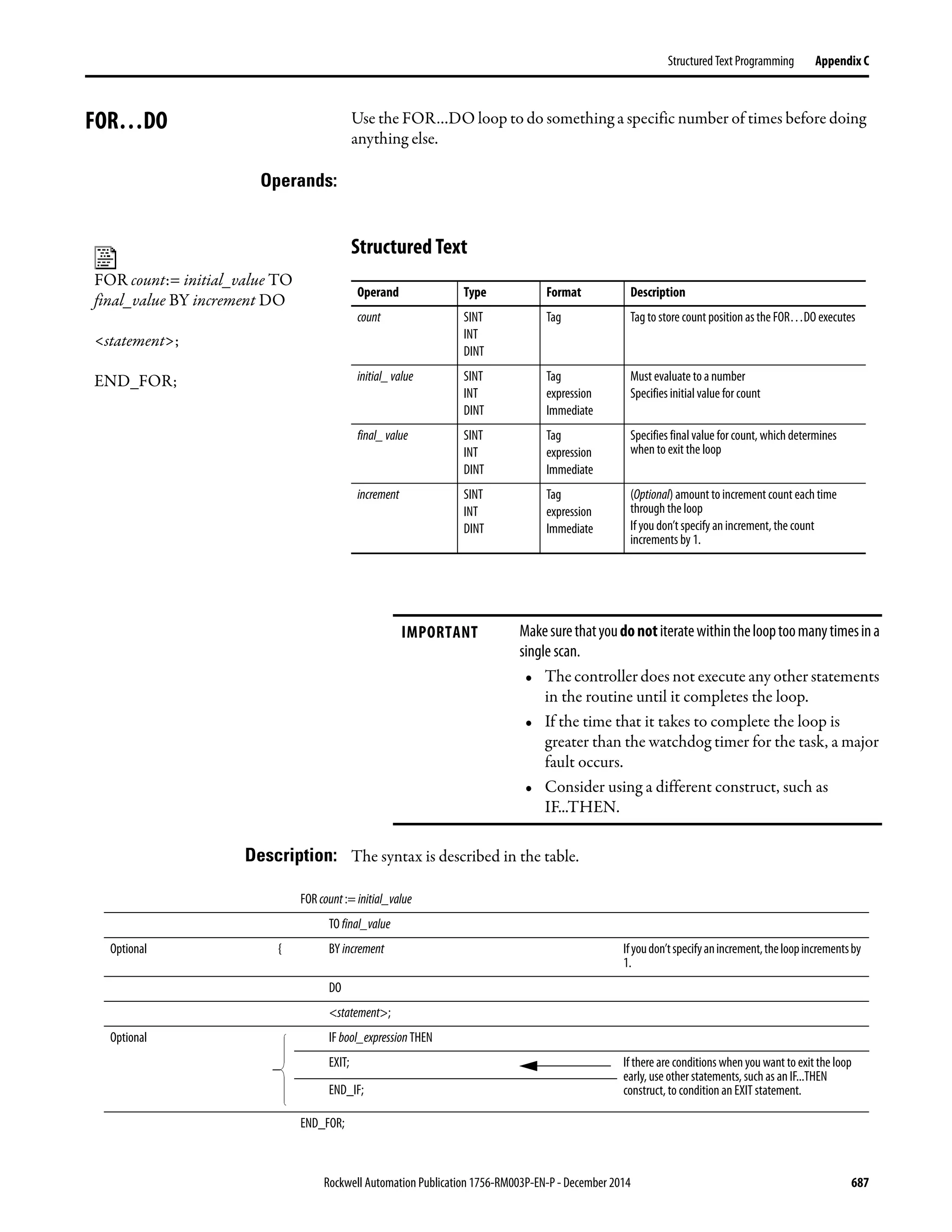
![688 Rockwell Automation Publication 1756-RM003P-EN-P - December 2014
Appendix C Structured Text Programming
The following diagrams show how a FOR...DO loop executes and how an EXIT
statement leaves the loop early.
Arithmetic Status Flags: Not affected
Fault Conditions:
Example 1:
Statement 1
Statement2
Statement 3
Statement 4
…
DonexNumberOf
Times?
No
Yes
Rest Of The Routine
Statement 1
Statement 2
Statement 3
Statement 4
…
Exit ?
DonexNumberOf
Times?
No
Yes
Rest Of The Routine
Yes
No
The FOR…DO loop executes a specific number of times. To stop the loop before the count reaches the last value, use an EXIT
statement.
A major fault will occur if Fault type Fault code
The construct loops too long. 6 1
If you want this Enter this structured text
Clear bits 0…31 in an array of BOOLs:
1. Initialize the subscript tag to 0.
2. Cleararray[subscript] . For example, when
subscript = 5, clear array[5].
3. Add 1 to subscript.
4. If subscript is ≤ to31, repeat 2 and 3.
Otherwise, stop.
For subscript:=0 to 31 by 1 do
array[subscript] := 0;
End_for;](https://image.slidesharecdn.com/1756-rm003-en-p-150617024022-lva1-app6892/75/1756-rm003-en-p-688-2048.jpg)
![Rockwell Automation Publication 1756-RM003P-EN-P - December 2014 689
Structured Text Programming Appendix C
Example 2:
If you want this Enter this structured text
A user-defined data type (structure) stores the following information about an
item in your inventory:
• Barcode ID of the item (string data type)
• Quantity in stock of the item (DINT data type)
Anarrayoftheabovestructurecontainsan elementforeachdifferentiteminyour
inventory.Youwanttosearchthearrayforaspecificproduct(useitsbarcode)and
determine the quantity that is in stock.
1. Get the size (number of items) of theInventory array and store the result in
Inventory_Items (DINT tag).
2. Initialize the position tag to 0.
3. If Barcode matches the ID of an item in the array, then:
a. Set theQuantity tag = Inventory[position].Qty. This produces the quantity
in stock of the item.
b. Stop.
Barcode is a string tag that stores the bar code of the item for which you are
searching. For example, when
position= 5, compare Barcode to Inventory[5].ID.
4. Add 1 toposition.
5. Ifpositionis≤to(Inventory_Items-1),repeat3and4.Sinceelementnumbers
start at 0, the last element is 1 less than the number of elements in the array.
Otherwise, stop.
SIZE(Inventory,0,Inventory_Items);
For position:=0 toInventory_Items - 1 do
If Barcode = Inventory[position].ID then
Quantity := Inventory[position].Qty;
Exit;
End_if;
End_for;](https://image.slidesharecdn.com/1756-rm003-en-p-150617024022-lva1-app6892/75/1756-rm003-en-p-689-2048.jpg)

![Rockwell Automation Publication 1756-RM003P-EN-P - December 2014 691
Structured Text Programming Appendix C
The following diagrams show how a WHILE...DO loop executes and how an
EXIT statement leaves the loop early.
Arithmetic Status Flags: Not affected
Fault Conditions:
Example 1:
While the bool_expression is true, the controller
executes only the statements within the WHILE…DO loop.
Tostoptheloopbeforetheconditionsaretrue,useanEXITstatement.
Statement 1
Statement 2
Statement 3
Statement 4
…
Exit ?
BOOL expression
True
False
Rest Of The Routine
Yes
No
Statement 1
Statement 2
Statement 3
Statement 4
…
BOOL expression
True
False
Rest Of The Routine
A major fault will occur if Fault type Fault code
The construct loops too long 6 1
If you want this Enter this structured text
The WHILE...DO loop evaluates its conditions first. If the conditions are true, the
controller then executes the statements within the loop.
This differs from the REPEAT...UNTIL loop because the REPEAT...UNTIL loop
executesthestatementsintheconstructandthendeterminesiftheconditionsare
true before executing the statements again. The statements in a REPEAT...UNTIL
looparealwaysexecutedatleastonce.ThestatementsinaWHILE...DOloopmight
never be executed.
pos:= 0;
While ((pos <= 100) & structarray[pos].value <> targetvalue)) do
pos := pos + 2;
String_tag.DATA[pos] := SINT_array[pos];
end_while;](https://image.slidesharecdn.com/1756-rm003-en-p-150617024022-lva1-app6892/75/1756-rm003-en-p-691-2048.jpg)
![692 Rockwell Automation Publication 1756-RM003P-EN-P - December 2014
Appendix C Structured Text Programming
Example 2:
If you want this Enter this structured text
Move ASCII characters from a SINT array into a string tag. (In a SINT array, each
element holds one character.) Stop when you reach the carriage return.
1. InitializeElement_number to 0.
2. Count the number of elements inSINT_array (array that contains the ASCII
characters) and store the result in SINT_array_size (DINT tag).
3. If the character atSINT_array[element_number] = 13 (decimal value of the
carriage return), then stop.
4. SetString_tag[element_number] = the characterat
SINT_array[element_number].
5. Add 1 to element_number. This lets the controller check the next character in
SINT_array.
6. Set the Length member of String_tag = element_number. (This records the
number of characters inString_tag so far.)
7. If element_number = SINT_array_size, then stop. (You are at the end of the
array and it does not contain a carriage return.)
8. Go to step 3.
element_number := 0;
SIZE(SINT_array, 0, SINT_array_size);
While SINT_array[element_number] <> 13 do
String_tag.DATA[element_number] := SINT_array[element_number];
element_number := element_number + 1;
String_tag.LEN := element_number;
If element_number = SINT_array_sizethen
exit;
end_if;
end_while;](https://image.slidesharecdn.com/1756-rm003-en-p-150617024022-lva1-app6892/75/1756-rm003-en-p-692-2048.jpg)

![694 Rockwell Automation Publication 1756-RM003P-EN-P - December 2014
Appendix C Structured Text Programming
The following diagrams show how a REPEAT...UNTIL loop executes and how
an EXIT statement leaves the loop early.
Arithmetic Status Flags: Not affected
Fault Conditions:
Example 1:
While the bool_expression is false, the controller executes
only the statements within the REPEAT…UNTIL loop.
To stop the loop before the conditions are false, use an EXIT
statement.
Statement 1
Statement 2
Statement 3
Statement 4
…
BOOL expression
False
True
Rest Of The Routine
BOOL expression
False
True
Rest Of The Routine
Statement 1
Statement 2
Statement 3
statement 4
…
Exit ? Yes
No
A major fault will occur if Fault type Fault code
The construct loops too long 6 1
If you want this Enter this structured text
The REPEAT...UNTIL loop executes the statements in the construct and then
determines if the conditions are truebefore executing the statements again.
This differs from the WHILE...DO loop because the WHILE...DO The WHILE...DO
loop evaluates its conditions first. If the conditions are true, the controller then
executes the statements within the loop. The statements in a REPEAT...UNTIL loop
are always executed at least once. The statements in a WHILE...DO loop might
never be executed.
pos:= -1;
REPEAT
pos := pos + 2;
UNTIL ((pos = 101) OR (structarray[pos].value = targetvalue))
end_repeat;](https://image.slidesharecdn.com/1756-rm003-en-p-150617024022-lva1-app6892/75/1756-rm003-en-p-694-2048.jpg)
![Rockwell Automation Publication 1756-RM003P-EN-P - December 2014 695
Structured Text Programming Appendix C
Example 2:
If you want this Enter this structured text
Move ASCII characters from a SINT array into a string tag. (In a SINT array, each
element holds one character.) Stop when you reach the carriage return.
1. InitializeElement_number to 0.
2. Count the number of elements inSINT_array (array that contains the ASCII
characters) and store the result in SINT_array_size (DINT tag).
3. SetString_tag[element_number] = the characterat
SINT_array[element_number].
4. Add 1 to element_number. This lets the controller check the next character in
SINT_array.
5. Set the Length member of String_tag = element_number. (This records the
number of characters inString_tag so far.)
6. If element_number = SINT_array_size, then stop. (You are at the end of the
array and it does not contain a
carriage return.)
7. If the character atSINT_array[element_number] = 13 (decimal value of the
carriage return), then stop.
Otherwise, go tostep 3.
element_number := 0;
SIZE(SINT_array, 0, SINT_array_size);
Repeat
String_tag.DATA[element_number] := SINT_array[element_number];
element_number := element_number + 1;
String_tag.LEN := element_number;
If element_number = SINT_array_sizethen
exit;
end_if;
Until SINT_array[element_number] = 13
end_repeat;](https://image.slidesharecdn.com/1756-rm003-en-p-150617024022-lva1-app6892/75/1756-rm003-en-p-695-2048.jpg)
![696 Rockwell Automation Publication 1756-RM003P-EN-P - December 2014
Appendix C Structured Text Programming
Comments To make your structured text easier to interpret, add comments to it.
• Comments let you use plain language to describe how your structured text
works.
• Comments do not affect the execution of the structured text.
The table describes how to add comments to your structured text.
The table shows some examples.
To add a comment Use one of these formats
On a single line //comment
(*comment*)
/*comment*/
At the end of a line of structured text
Within a line of structured text (*comment*)
/*comment*/
That spans more than one line (*start of comment . . . end of
comment*)
/*start of comment . . . end of
comment*/
Format Example
//comment At the beginning of a line
//Check conveyor belt direction
IF conveyor_direction THEN...
At the end of a line
ELSE //If conveyor isn’t moving, set alarm light
light := 1;
END_IF;
(*comment*) Sugar.Inlet[:=]1;(*open the inlet*)
IF Sugar.Low (*low level LS*)& Sugar.High (*high level LS*)THEN...
(*Controls the speed of the recirculation pump. The speed depends on the temperature in thetank.*)
IF tank.temp > 200 THEN...
/*comment*/ Sugar.Inlet:=0;/*close the inlet*/
IF bar_code=65 /*A*/ THEN...
/*Gets thenumber of elements in the Inventory array and stores the value in the Inventory_Items tag*/
SIZE(Inventory,0,Inventory_Items);](https://image.slidesharecdn.com/1756-rm003-en-p-150617024022-lva1-app6892/75/1756-rm003-en-p-696-2048.jpg)
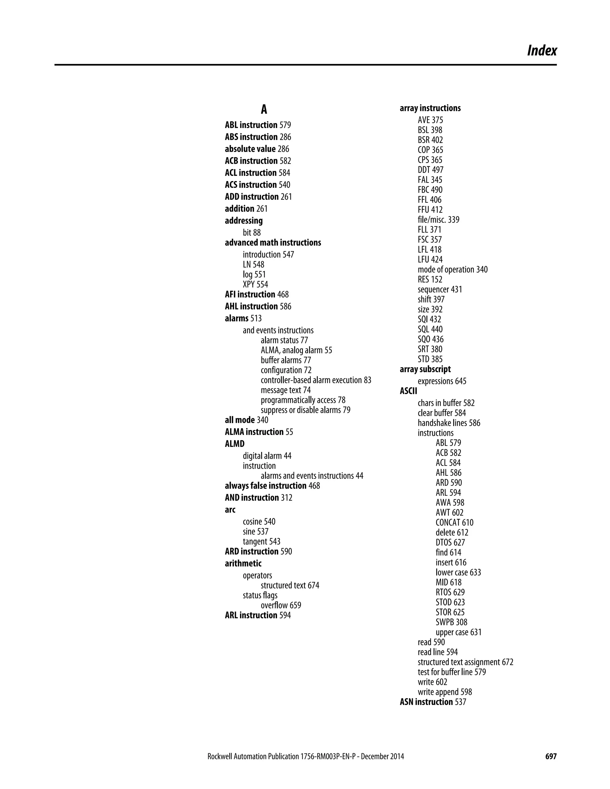

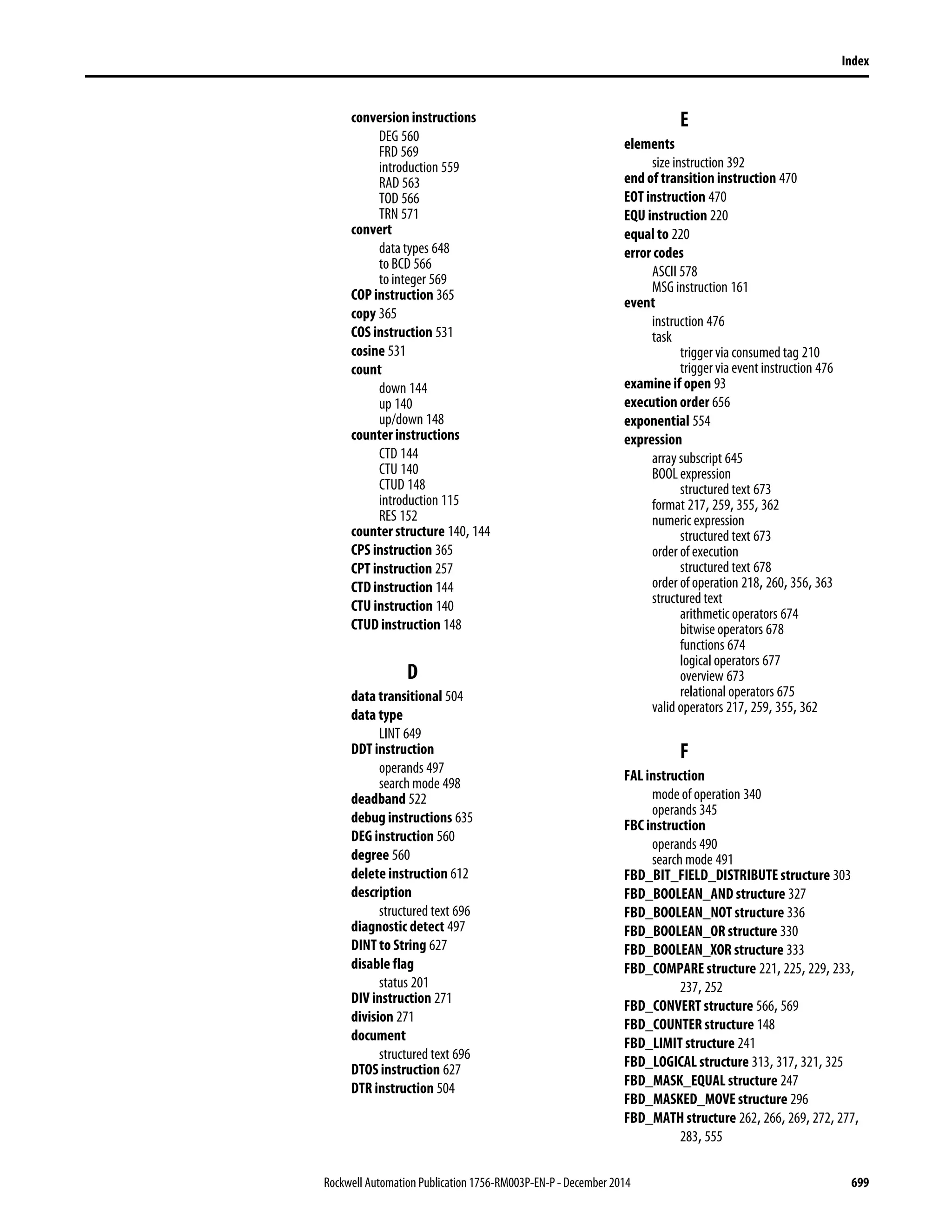


![6104525_Anderson_BSN499-11B_Jan_Final_Project_Power_Point[1]](https://cdn.slidesharecdn.com/ss_thumbnails/02254436-efd1-4663-9789-ebfdf3209389-150422125135-conversion-gate01-thumbnail.jpg?width=640&height=640&fit=bounds)


