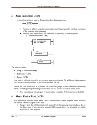
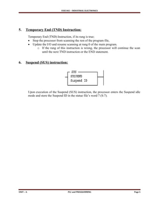
03EC402 – INDUSTRIAL ELECTRONICS
L – 19: Data Handling Instructions in PLC Programming
1. Data Handling Instructions
The instructions like timers and counters handle single bit of data (0 or 1). Data handling
instructions deals with more than a bit, like;
 Moving or transferring numbers from one memory location to another,
 Comparing data values, or
 Performing simple arithmetic operations,
a) Move (MOV) Instructions
This output instruction moves the source value to the destination location. As long as the rung
remains true, the instruction moves the data on each scan.
Entering parameters;
 Source is the address or constant of the data you want to move,
 Destination is the address where the instruction moves the data,
Application note: if you wish to move one word of data without affecting the math flags,
use a copy (COP) instruction with a length of one word instead of the MOV instruction.
Using MOV for variable initialization
S:1/15 is a bit in status date file that is energized for exactly one PLC scan when the PLC is
placed in run mode.
 It can be used to condition the initialization of variables used elsewhere in the ladder
logic.
UNIT – 4: PLC and PROGRAMMING Page 1
03EC402 – INDUSTRIAL ELECTRONICS
b) Masked Move (MVM) instructions,
The MVM instruction is a word instruction that moves data from a source location to a
destination and allows portions of the destination data to be masked by a separate word.
As long as the rung remains true, the instruction moves the data on each scan.
Entering parameters;
 Source is the address of the data you want to move,
 Mask is the address of the mask through which the instruction moves data;
 Destination is the address where the instruction ‘move’ data.
c) Bitwise AND instruction
The instruction performs a bit-by-bit logical AND. The operation is performed using the value at
source A and the value at source B.
 The result is stored in the destination.
 Source A and B can either be a word address or a constant; however, both sources cannot
be a constant.
 The destination must be a word address.
Application note:
When entering constants, you can used the ampersand (&) operator to change the radix of the
your entry.
 Instead of entering – 1 as a constant, you could enter &B1111111111111111 or &HFFFF
UNIT – 4: PLC and PROGRAMMING Page 2
03EC402 – INDUSTRIAL ELECTRONICS
d) Clear (CLR) Instruction
The CLR instruction is used to set the destination value of a word to zero.
This instruction always set the zero (Z) flag (S:0/2).
 Other arithmetic status bits are always cleared (reset)
o S:0/0, carry (C)
o S:0/1, overflow (V)
o S:0/3, sign (S)
2. Math Instructions:
Math instructions are used in ladder logic for various arithmetic operations like;
 Addition,
 Subtraction,
 Multiplication,
 Division
Source is the value / (values) to be used for the numerical, logic and moving operation.
 An instruction with two source operands in both operands does not accept program
constants.
Destination is the address of the operation’s end.
 Signed integers are contained in the complimentary shape of two and refer to parameters
of source and destination.
Location of math instructions in ladder logic will decide the operation performed,
 i.e If the (AB+C) operation is required, the ADD operation will occur before the MUL.
There are math instructions such as;
 ADD (addition),
 SUB (subtraction),
 MUL(multiplication),
 DIV (division),
 SQR (square root),
 NEG (negative a value -2’s
complementary),
 TOD ( convert integer to BCD),
 FRD (convert from BCD to integer)
UNIT – 4: PLC and PROGRAMMING Page 3
03EC402 – INDUSTRIAL ELECTRONICS
3. Jump Instructions (JMP)
A jump instruction is used to skip portion of the ladder program,
 Jumping to a label saves the scanning time of the program by omitting a segment
of the program until necessary.
 Jumping backwards allows the controller to repeatedly execute segments.
o Jump to subroutine (JSR)
The instructions for;
 Jump to Subroutine (JSR),
 Subroutine (SBR),
 Return (RET),
Are used to guide the controller to execute a separate subroutine file within the ladder system
and return to the instructions as per the instructions for JSR.
When the JSR instruction is executed, the controller jumps to the subroutine instruction
(SBR) at the beginning of the target subroutine file and resume execution at that point.
 You cannot jump into any part of a subroutine except the first instruction in that file.
4. Master Control Reset (MCR)
Use pair-based Master Control Reset (MCR) instructions to create program zones that turn
off all non-retentive outputs in the area.
 Rungs within the MCR zone are still scanned, but the scanning time is reduced due to
the false state of non-retentive outputs MCR zones allow you to enable or inhibit
segments of your program.
UNIT – 4: PLC and PROGRAMMING Page 4
03EC402 – INDUSTRIAL ELECTRONICS
5. Temporary End (TND) Instruction:
Temporary End (TND) Instruction, if its rung is true;
 Stop the processor from scanning the rest of the program file,
 Update the I/O and resume scanning at rung 0 of the main program.
o If the rung of this instruction is wrong, the processor will continue the scan
until the next TND instruction or the END statement.
6. Suspend (SUS) instruction:
Upon execution of the Suspend (SUS) instruction, the processor enters the Suspend idle
mode and store the Suspend ID in the statue file’s word 7 (S:7).
UNIT – 4: PLC and PROGRAMMING Page 5

data handling fuctions for programmable logic controller

  • 1.
    03EC402 – INDUSTRIALELECTRONICS L – 19: Data Handling Instructions in PLC Programming 1. Data Handling Instructions The instructions like timers and counters handle single bit of data (0 or 1). Data handling instructions deals with more than a bit, like;  Moving or transferring numbers from one memory location to another,  Comparing data values, or  Performing simple arithmetic operations, a) Move (MOV) Instructions This output instruction moves the source value to the destination location. As long as the rung remains true, the instruction moves the data on each scan. Entering parameters;  Source is the address or constant of the data you want to move,  Destination is the address where the instruction moves the data, Application note: if you wish to move one word of data without affecting the math flags, use a copy (COP) instruction with a length of one word instead of the MOV instruction. Using MOV for variable initialization S:1/15 is a bit in status date file that is energized for exactly one PLC scan when the PLC is placed in run mode.  It can be used to condition the initialization of variables used elsewhere in the ladder logic. UNIT – 4: PLC and PROGRAMMING Page 1
  • 2.
    03EC402 – INDUSTRIALELECTRONICS b) Masked Move (MVM) instructions, The MVM instruction is a word instruction that moves data from a source location to a destination and allows portions of the destination data to be masked by a separate word. As long as the rung remains true, the instruction moves the data on each scan. Entering parameters;  Source is the address of the data you want to move,  Mask is the address of the mask through which the instruction moves data;  Destination is the address where the instruction ‘move’ data. c) Bitwise AND instruction The instruction performs a bit-by-bit logical AND. The operation is performed using the value at source A and the value at source B.  The result is stored in the destination.  Source A and B can either be a word address or a constant; however, both sources cannot be a constant.  The destination must be a word address. Application note: When entering constants, you can used the ampersand (&) operator to change the radix of the your entry.  Instead of entering – 1 as a constant, you could enter &B1111111111111111 or &HFFFF UNIT – 4: PLC and PROGRAMMING Page 2
  • 3.
    03EC402 – INDUSTRIALELECTRONICS d) Clear (CLR) Instruction The CLR instruction is used to set the destination value of a word to zero. This instruction always set the zero (Z) flag (S:0/2).  Other arithmetic status bits are always cleared (reset) o S:0/0, carry (C) o S:0/1, overflow (V) o S:0/3, sign (S) 2. Math Instructions: Math instructions are used in ladder logic for various arithmetic operations like;  Addition,  Subtraction,  Multiplication,  Division Source is the value / (values) to be used for the numerical, logic and moving operation.  An instruction with two source operands in both operands does not accept program constants. Destination is the address of the operation’s end.  Signed integers are contained in the complimentary shape of two and refer to parameters of source and destination. Location of math instructions in ladder logic will decide the operation performed,  i.e If the (AB+C) operation is required, the ADD operation will occur before the MUL. There are math instructions such as;  ADD (addition),  SUB (subtraction),  MUL(multiplication),  DIV (division),  SQR (square root),  NEG (negative a value -2’s complementary),  TOD ( convert integer to BCD),  FRD (convert from BCD to integer) UNIT – 4: PLC and PROGRAMMING Page 3
  • 4.
    03EC402 – INDUSTRIALELECTRONICS 3. Jump Instructions (JMP) A jump instruction is used to skip portion of the ladder program,  Jumping to a label saves the scanning time of the program by omitting a segment of the program until necessary.  Jumping backwards allows the controller to repeatedly execute segments. o Jump to subroutine (JSR) The instructions for;  Jump to Subroutine (JSR),  Subroutine (SBR),  Return (RET), Are used to guide the controller to execute a separate subroutine file within the ladder system and return to the instructions as per the instructions for JSR. When the JSR instruction is executed, the controller jumps to the subroutine instruction (SBR) at the beginning of the target subroutine file and resume execution at that point.  You cannot jump into any part of a subroutine except the first instruction in that file. 4. Master Control Reset (MCR) Use pair-based Master Control Reset (MCR) instructions to create program zones that turn off all non-retentive outputs in the area.  Rungs within the MCR zone are still scanned, but the scanning time is reduced due to the false state of non-retentive outputs MCR zones allow you to enable or inhibit segments of your program. UNIT – 4: PLC and PROGRAMMING Page 4
  • 5.
    03EC402 – INDUSTRIALELECTRONICS 5. Temporary End (TND) Instruction: Temporary End (TND) Instruction, if its rung is true;  Stop the processor from scanning the rest of the program file,  Update the I/O and resume scanning at rung 0 of the main program. o If the rung of this instruction is wrong, the processor will continue the scan until the next TND instruction or the END statement. 6. Suspend (SUS) instruction: Upon execution of the Suspend (SUS) instruction, the processor enters the Suspend idle mode and store the Suspend ID in the statue file’s word 7 (S:7). UNIT – 4: PLC and PROGRAMMING Page 5