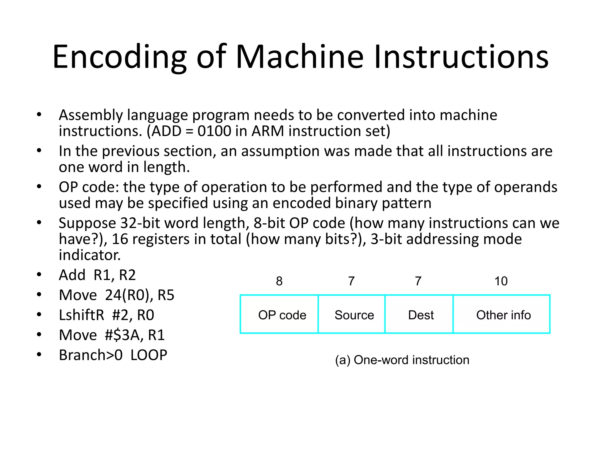
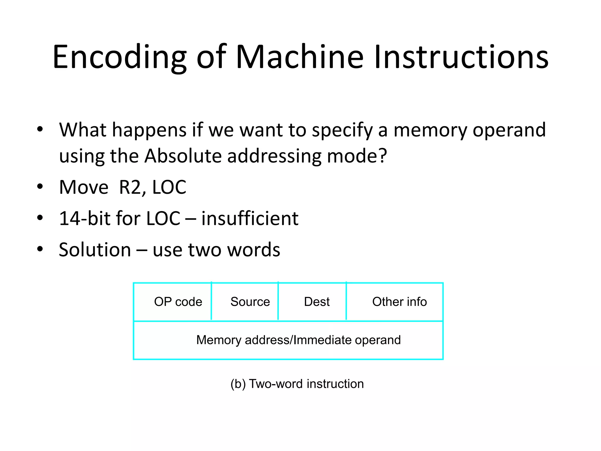
The document discusses different types of machine instructions including data transfer, data manipulation, and program control instructions. It also covers instruction encoding, where the operation code and operands are encoded into a binary pattern to specify the instruction. Instructions can be encoded into a single word or multiple words depending on the operands and addressing modes used. Encoding instructions into a fixed number of words results in a RISC architecture, while allowing variable length instructions creates a CISC architecture.
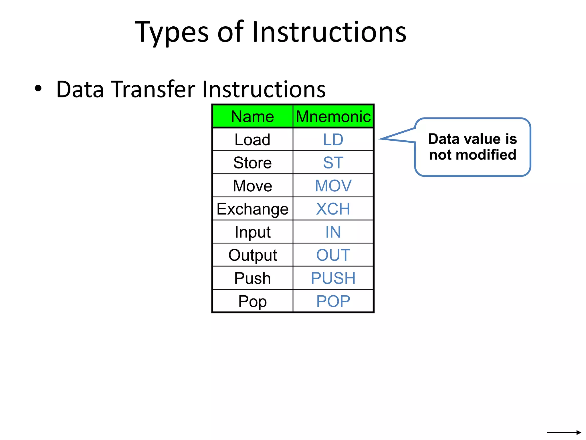
![Data Transfer Instructions
Mode Assembly Register Transfer
Direct address LD ADR AC ← M[ADR]
Indirect address LD @ADR AC ← M[M[ADR]]
Relative address LD $ADR AC ← M[PC+ADR]
Immediate operand LD #NBR AC ← NBR
Index addressing LD ADR(X) AC ← M[ADR+XR]
Register LD R1 AC ← R1
Register indirect LD (R1) AC ← M[R1]
Autoincrement LD (R1)+ AC ← M[R1], R1 ← R1+1](https://image.slidesharecdn.com/instructiontypes-210316075920/75/Instruction-types-3-2048.jpg)
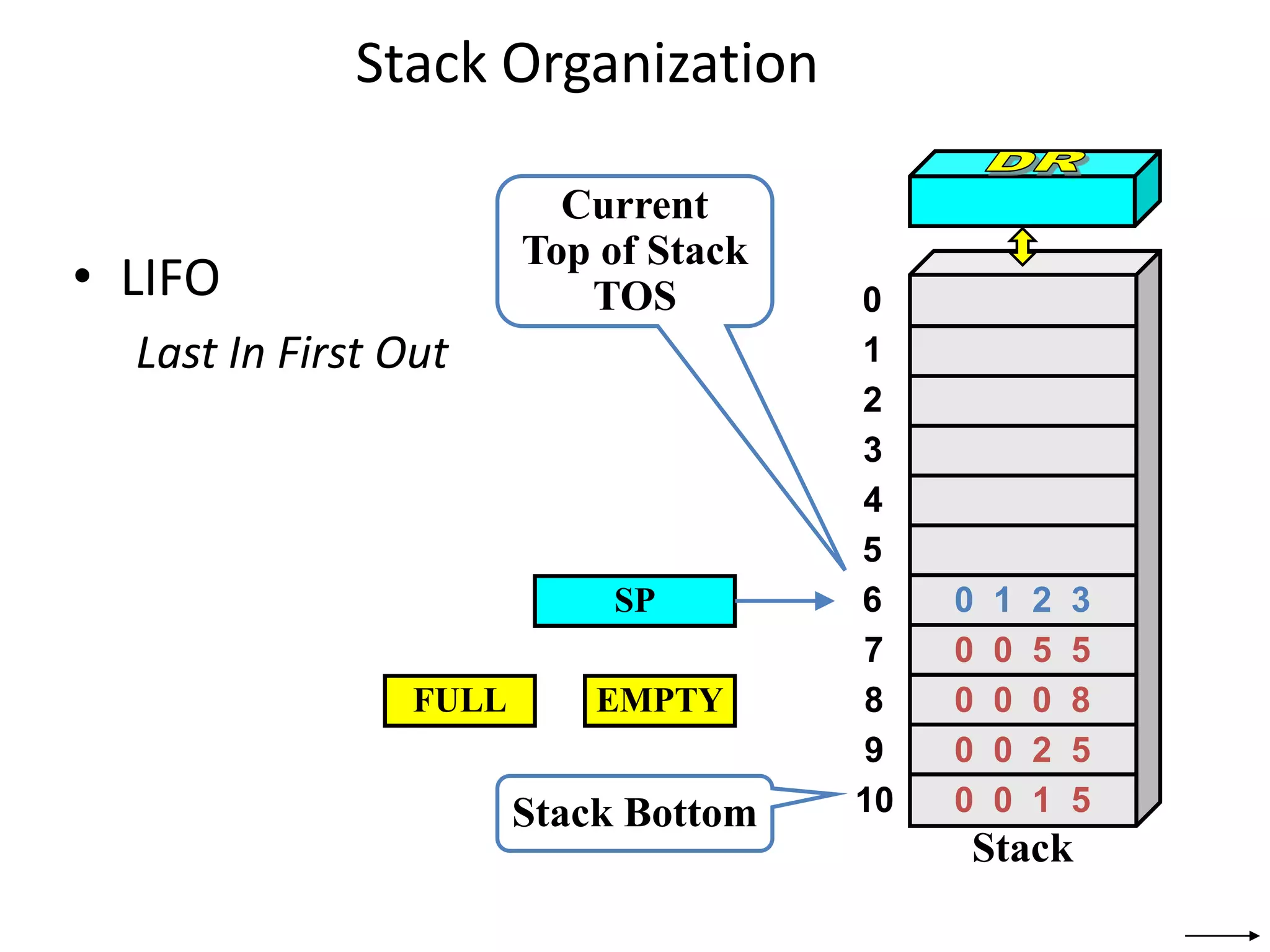
![Stack Organization
• PUSH
SP ← SP – 1
M[SP] ← DR
If (SP = 0) then (FULL ← 1)
EMPTY ← 0
SP
Stack Bottom
Current
Top of Stack
TOS 0
1
2
3
4
7
8
9
10
5
6
Stack
0 0 5 5
0 0 0 8
0 0 2 5
0 0 1 5
0 1 2 3
FULL EMPTY
1 6 9 0
1 6 9 0
Current
Top of Stack
TOS](https://image.slidesharecdn.com/instructiontypes-210316075920/75/Instruction-types-16-2048.jpg)
![Stack Organization
• POP
DR ← M[SP]
SP ← SP + 1
If (SP = 11) then (EMPTY ← 1)
FULL ← 0
SP
Stack Bottom
Current
Top of Stack
TOS 0
1
2
3
4
7
8
9
10
5
6
Stack
0 0 5 5
0 0 0 8
0 0 2 5
0 0 1 5
0 1 2 3
FULL EMPTY
1 6 9 0
1 6 9 0
Current
Top of Stack
TOS](https://image.slidesharecdn.com/instructiontypes-210316075920/75/Instruction-types-17-2048.jpg)
![0
1
2
102
202
201
200
100
101
Stack Organization
• Memory Stack
– PUSH
SP ← SP – 1
M[SP] ← DR
– POP
DR ← M[SP]
SP ← SP + 1
PC
AR
SP](https://image.slidesharecdn.com/instructiontypes-210316075920/75/Instruction-types-18-2048.jpg)
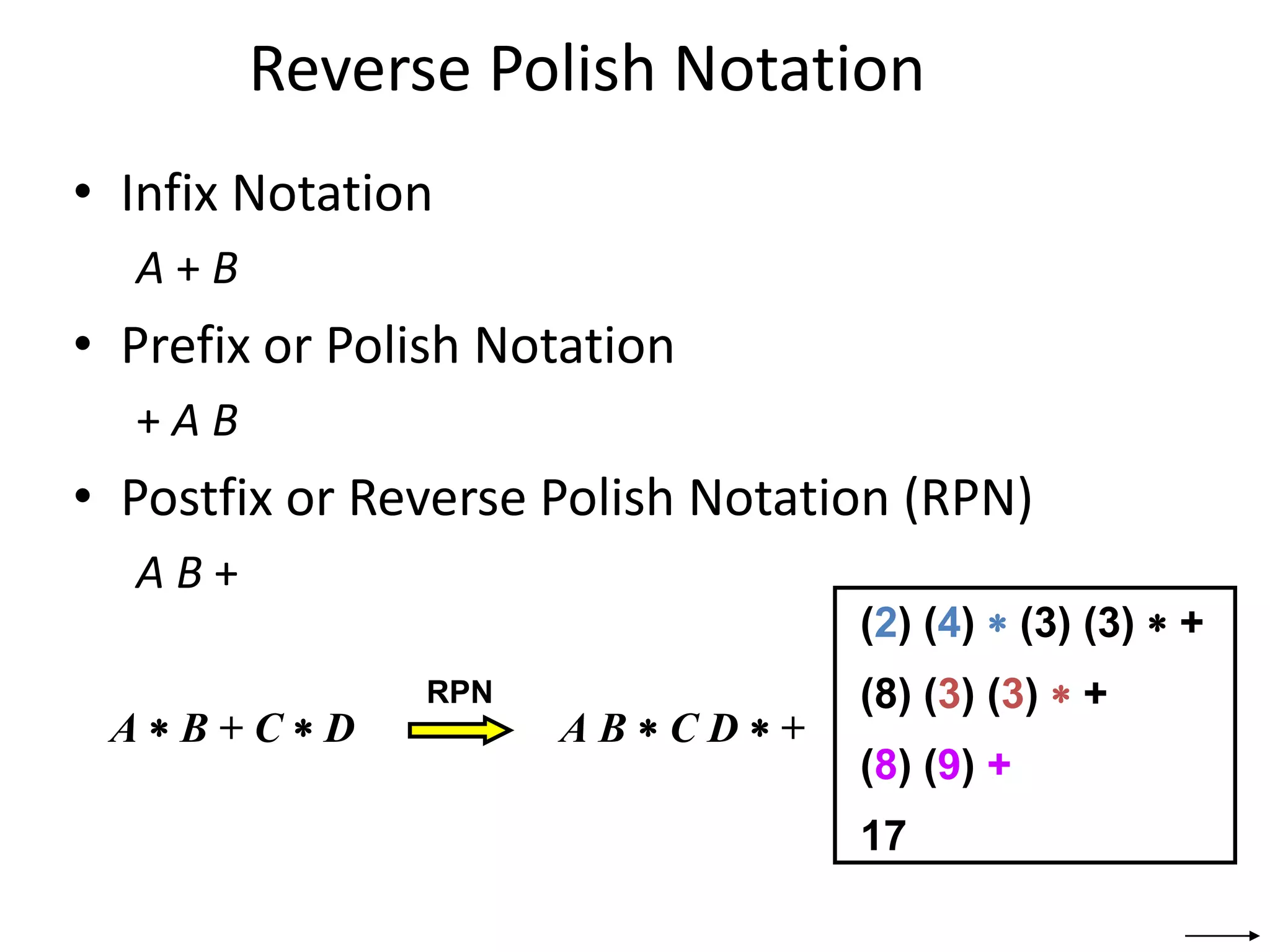
![Reverse Polish Notation
• Example
(A + B) ∗ [C ∗ (D + E) + F]
(A B +) (D E +) C ∗ ∗
F +](https://image.slidesharecdn.com/instructiontypes-210316075920/75/Instruction-types-20-2048.jpg)

![Multiplication and Division
• Not very popular (especially division)
• Multiply Ri, Rj
Rj ← [Ri] х [Rj]
• 2n-bit product case: high-order half in R(j+1)
• Divide Ri, Rj
Rj ← [Ri] / [Rj]
Quotient is in Rj, remainder may be placed in R(j+1)](https://image.slidesharecdn.com/instructiontypes-210316075920/75/Instruction-types-26-2048.jpg)