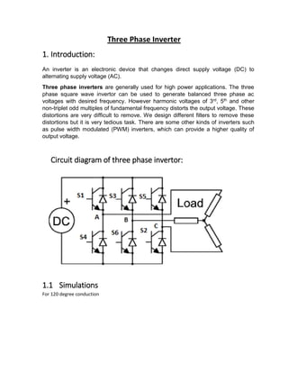
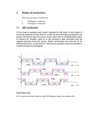
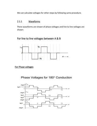
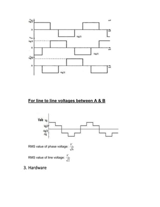
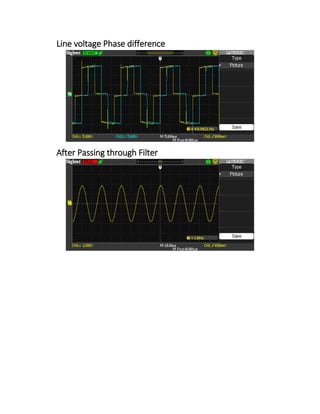
SlideShare a Scribd company logo
Three Phase Inverter
1. Introduction:
An inverter is an electronic device that changes direct supply voltage (DC) to
alternating supply voltage (AC).
Three phase inverters are generally used for high power applications. The three
phase square wave invertor can be used to generate balanced three phase ac
voltages with desired frequency. However harmonic voltages of 3rd, 5th and other
non-triplet odd multiples of fundamental frequency distorts the output voltage. These
distortions are very difficult to remove. We design different filters to remove these
distortions but it is very tedious task. There are some other kinds of inverters such
as pulse width modulated (PWM) inverters, which can provide a higher quality of
output voltage.
Circuit diagram of three phase invertor:
1.1 Simulations
For 120 degree conduction
Phase voltages will be as
Phase difference will be as
Line voltage will be as
Line voltage difference will be as
For 180 degree Conduction
Line voltage will be as
Line difference will be as
Phase voltage will be as
Phase difference will be as
2. Modes of conduction:
There are two modes of conduction:
i. 180 degrees’ conduction
ii. 120 degrees’ conduction
2.1 180o conduction:
In this mode of operation each switch conducts for half cycle. At any instant of
time three switches are ON. When S1 is ON, the terminal A gets connected to the
positive terminal of input DC source, at the same time its complementary switch
S4 remains off. Similarly, when S4 is ON, terminal A gets connected with the
negative terminal of the DC source. These combinations are same for S3, S6
(terminal B) and S5, S2 (terminal C). There are six possible modes of operation in
a cycle and each is of 60 degree.
Equivalent circuit
For Y-connected resistive load for step1 (0-60 degree), others are similar to this:
For step 1 (0-60 degree) S1, S6, S5 will conduct A and B will be connected with
positive terminal of DC source and C will be connected with negative terminal of
DC source. Equivalent resistance is equal to
𝑅𝑒𝑞 = 𝑅 +
𝑅 ∗ 𝑅
𝑅 + 𝑅
𝑅 +
𝑅
2
=
3𝑅
2
Current can be calculated as
𝑖 =
𝑉𝑔
𝑅𝑒𝑞
=
2𝑉𝑔
3𝑅
Phase Voltages can be calculated as
𝑉𝑎𝑛 = 𝑉𝑐𝑛 =
𝑅
2
3𝑅
2
∗ 𝑉𝑔 =
1
3
𝑉𝑔
𝑉𝑏𝑛 =
𝑅
3𝑅
2
∗ 𝑉𝑔 =
−2
3
𝑉𝑔
Line to line voltages can be calculated as
𝑉𝑎𝑏 = 𝑉𝑎𝑛 − 𝑉𝑏𝑛 = 𝑉𝑔
𝑉𝑏𝑐 = 𝑉𝑏𝑛 − 𝑉𝑐𝑛 = −𝑉𝑔
𝑉𝑐𝑎 = 𝑉𝑐𝑛 − 𝑉𝑎𝑛 = 0
We can calculate voltages for other steps by following same procedure.
2.1.1 Waveforms
There waveforms are shown of phase voltages and line to line voltages are
shown:
For line to line voltages between A & B
For Phase voltages
RMS value of phase voltage:
√2
3
𝑉𝑔
RMS value of line voltage: √
2
3
𝑉𝑔
2.2 1200 conduction:
In 120-degree conduction mode, only two switches conduct at the same time;
one upper switch and one lower switch. Each switch conducts for a duration of
1200 in one period of 3600 of the output voltage. The gating signal for each switch
is maintained for 120-degree. There are six sub-intervals of 600 each. The
operation of invertor during one cycle of input voltage can be explained in six
different steps. I have explained only on, others are similar to this.
In step 1 (0-60 degree) S6 and S1 is conducting as figure becomes:
Equivalent circuit
For Y-connected resistive load for step1 (0-60 degree)
Phase voltages can be calculated as:
𝑉𝑎𝑛 =
𝑉𝑔
2
𝑉𝑏𝑛 = −
𝑉𝑔
2
𝑉𝑐𝑛 = 0
𝑉𝑎𝑏 = 𝑉𝑔
𝑉𝑏𝑐 = 𝑉𝑐𝑎 =
−𝑉𝑔
2
2.2.1 Waveforms
For phase voltages
For line to line voltages between A & B
RMS value of phase voltage:
6
sV
RMS value of line voltage:
2
sV
3. Hardware
Waveforms
Across Phase voltage
Phase voltage (phase) difference
Line Voltage
Line voltage Phase difference
After Passing through Filter

More Related Content

What's hot

Power Electronics Chopper (dc – dc converter)
Power Electronics   Chopper (dc – dc converter)Power Electronics   Chopper (dc – dc converter)
Power Electronics Chopper (dc – dc converter)
Burdwan University
 
Synchronous generator
Synchronous generatorSynchronous generator
Synchronous generator
Power System Operation
 
Power electronics Phase Controlled Rectifiers - SCR
Power electronics   Phase Controlled Rectifiers - SCRPower electronics   Phase Controlled Rectifiers - SCR
Power electronics Phase Controlled Rectifiers - SCR
Burdwan University
 
dc to dc-converter
dc to dc-converterdc to dc-converter
dc to dc-converter
Student
 
Voltage Source Inverter
Voltage Source InverterVoltage Source Inverter
Voltage Source Inverter
PreetamJadhav2
 
SIMULATION AND STUDY OF MULTILEVEL INVERTER (ppt)
SIMULATION AND STUDY OF MULTILEVEL INVERTER (ppt)SIMULATION AND STUDY OF MULTILEVEL INVERTER (ppt)
SIMULATION AND STUDY OF MULTILEVEL INVERTER (ppt)
Arpit Kurel
 
INVERTERS PRESENTATION
INVERTERS PRESENTATIONINVERTERS PRESENTATION
INVERTERS PRESENTATION
Rajesh V
 
Buck-Boost Converter
Buck-Boost ConverterBuck-Boost Converter
Buck-Boost Converter
Sagar Patil
 
Inverters (DC-AC)
Inverters (DC-AC)Inverters (DC-AC)
Inverters (DC-AC)
Taimur Ijaz
 
VSC based HVDC system
VSC based HVDC systemVSC based HVDC system
VSC based HVDC system
mdhsudhan
 
Motor drives
Motor drivesMotor drives
Motor drives
Nilesh Kulkarni
 
Inverter
InverterInverter
Inverter
InverterInverter
Inverter
raguprince
 
Voltage source Converters as a building block of HVDC and FACTS
Voltage source Converters as a building block of HVDC and FACTSVoltage source Converters as a building block of HVDC and FACTS
Voltage source Converters as a building block of HVDC and FACTS
Karthik Bharadwaj
 
BUCK CONVERTER
BUCK CONVERTERBUCK CONVERTER
BUCK CONVERTER
NIT MEGHALAYA
 
Transformer basic
Transformer basicTransformer basic
Transformer basic
BHAGWAN PRASAD
 
Two Quadrant chopper
Two Quadrant chopperTwo Quadrant chopper
Two Quadrant chopper
Ashish Kashyap
 
Unit I design of electrical machines
Unit I   design of electrical machinesUnit I   design of electrical machines
Unit I design of electrical machines
nganesh90
 
A presentation on inverter by manoj
A presentation on inverter by manojA presentation on inverter by manoj
A presentation on inverter by manoj
IACM SmartLearn Ltd.
 

What's hot (20)

Power Electronics Chopper (dc – dc converter)
Power Electronics   Chopper (dc – dc converter)Power Electronics   Chopper (dc – dc converter)
Power Electronics Chopper (dc – dc converter)
 
Synchronous generator
Synchronous generatorSynchronous generator
Synchronous generator
 
Power electronics Phase Controlled Rectifiers - SCR
Power electronics   Phase Controlled Rectifiers - SCRPower electronics   Phase Controlled Rectifiers - SCR
Power electronics Phase Controlled Rectifiers - SCR
 
dc to dc-converter
dc to dc-converterdc to dc-converter
dc to dc-converter
 
Voltage Source Inverter
Voltage Source InverterVoltage Source Inverter
Voltage Source Inverter
 
SIMULATION AND STUDY OF MULTILEVEL INVERTER (ppt)
SIMULATION AND STUDY OF MULTILEVEL INVERTER (ppt)SIMULATION AND STUDY OF MULTILEVEL INVERTER (ppt)
SIMULATION AND STUDY OF MULTILEVEL INVERTER (ppt)
 
Tap Changer
Tap ChangerTap Changer
Tap Changer
 
INVERTERS PRESENTATION
INVERTERS PRESENTATIONINVERTERS PRESENTATION
INVERTERS PRESENTATION
 
Buck-Boost Converter
Buck-Boost ConverterBuck-Boost Converter
Buck-Boost Converter
 
Inverters (DC-AC)
Inverters (DC-AC)Inverters (DC-AC)
Inverters (DC-AC)
 
VSC based HVDC system
VSC based HVDC systemVSC based HVDC system
VSC based HVDC system
 
Motor drives
Motor drivesMotor drives
Motor drives
 
Inverter
InverterInverter
Inverter
 
Inverter
InverterInverter
Inverter
 
Voltage source Converters as a building block of HVDC and FACTS
Voltage source Converters as a building block of HVDC and FACTSVoltage source Converters as a building block of HVDC and FACTS
Voltage source Converters as a building block of HVDC and FACTS
 
BUCK CONVERTER
BUCK CONVERTERBUCK CONVERTER
BUCK CONVERTER
 
Transformer basic
Transformer basicTransformer basic
Transformer basic
 
Two Quadrant chopper
Two Quadrant chopperTwo Quadrant chopper
Two Quadrant chopper
 
Unit I design of electrical machines
Unit I   design of electrical machinesUnit I   design of electrical machines
Unit I design of electrical machines
 
A presentation on inverter by manoj
A presentation on inverter by manojA presentation on inverter by manoj
A presentation on inverter by manoj
 

Similar to three phase inverter

PE UNIT IV - INVERTERS.pptx
PE UNIT IV - INVERTERS.pptxPE UNIT IV - INVERTERS.pptx
PE UNIT IV - INVERTERS.pptx
MuthuKumar158260
 
PE UNIT IV.pptx
PE UNIT IV.pptxPE UNIT IV.pptx
PE UNIT IV.pptx
Karthik Kathan
 
Unit-5 AC-AC Cycloconverter
Unit-5 AC-AC CycloconverterUnit-5 AC-AC Cycloconverter
Unit-5 AC-AC Cycloconverter
johny renoald
 
Simplified analysis of graetz circuit copy - copy
Simplified analysis of graetz circuit   copy - copySimplified analysis of graetz circuit   copy - copy
Simplified analysis of graetz circuit copy - copy
Vert Wheeler
 
G1013238
G1013238G1013238
G1013238
IJERD Editor
 
l4-ac-ac converters.ppt
l4-ac-ac converters.pptl4-ac-ac converters.ppt
l4-ac-ac converters.ppt
antexnebyu
 
report of power electronics
report of power electronicsreport of power electronics
report of power electronics
Mohamad Nur Afham Shamsudin
 
Some Aspects on 3-Phase Bridge Inverter (180 Degree Mode)
Some Aspects on 3-Phase Bridge Inverter (180 Degree Mode)Some Aspects on 3-Phase Bridge Inverter (180 Degree Mode)
Some Aspects on 3-Phase Bridge Inverter (180 Degree Mode)
International Journal of Engineering Inventions www.ijeijournal.com
 
Power Circuits and Transforers-Unit 6 Labvolt Student Manual
Power Circuits and Transforers-Unit 6 Labvolt Student ManualPower Circuits and Transforers-Unit 6 Labvolt Student Manual
Power Circuits and Transforers-Unit 6 Labvolt Student Manual
phase3-120A
 
EMI_U_III_PPT_pptx (1).pptx
EMI_U_III_PPT_pptx (1).pptxEMI_U_III_PPT_pptx (1).pptx
EMI_U_III_PPT_pptx (1).pptx
sameed4
 
RGPV EX7102 UNITIII
RGPV EX7102 UNITIIIRGPV EX7102 UNITIII
RGPV EX7102 UNITIII
Mani Deep Dutt
 
Lecture6_Electrical engingveering_AC.pptx
Lecture6_Electrical engingveering_AC.pptxLecture6_Electrical engingveering_AC.pptx
Lecture6_Electrical engingveering_AC.pptx
Almasifidi
 
unit-1-Three phase circuits and power systems.pdf
unit-1-Three phase circuits and power systems.pdfunit-1-Three phase circuits and power systems.pdf
unit-1-Three phase circuits and power systems.pdf
deepaMS4
 
Cd35455460
Cd35455460Cd35455460
Cd35455460
IJERA Editor
 
Analisis result power e
Analisis result power eAnalisis result power e
Analisis result power eDen Besut
 
Three Phase Rectifier By Vivek Ahlawat
Three Phase Rectifier By Vivek AhlawatThree Phase Rectifier By Vivek Ahlawat
Three Phase Rectifier By Vivek Ahlawat
VIVEK AHLAWAT
 
Lecture slides_Ch 8 power electronics daniel hart.pdf
Lecture slides_Ch 8 power electronics daniel hart.pdfLecture slides_Ch 8 power electronics daniel hart.pdf
Lecture slides_Ch 8 power electronics daniel hart.pdf
GIFT University, Gujranwala, Pakistan
 
Electrical and Electronics Engineering
Electrical and Electronics EngineeringElectrical and Electronics Engineering
Electrical and Electronics Engineering
Ekeeda
 
yd_convertion_transdformer.docx
yd_convertion_transdformer.docxyd_convertion_transdformer.docx
yd_convertion_transdformer.docx
FREELANCER
 

Similar to three phase inverter (20)

PE UNIT IV - INVERTERS.pptx
PE UNIT IV - INVERTERS.pptxPE UNIT IV - INVERTERS.pptx
PE UNIT IV - INVERTERS.pptx
 
PE UNIT IV.pptx
PE UNIT IV.pptxPE UNIT IV.pptx
PE UNIT IV.pptx
 
Unit-5 AC-AC Cycloconverter
Unit-5 AC-AC CycloconverterUnit-5 AC-AC Cycloconverter
Unit-5 AC-AC Cycloconverter
 
Simplified analysis of graetz circuit copy - copy
Simplified analysis of graetz circuit   copy - copySimplified analysis of graetz circuit   copy - copy
Simplified analysis of graetz circuit copy - copy
 
G1013238
G1013238G1013238
G1013238
 
l4-ac-ac converters.ppt
l4-ac-ac converters.pptl4-ac-ac converters.ppt
l4-ac-ac converters.ppt
 
report of power electronics
report of power electronicsreport of power electronics
report of power electronics
 
Some Aspects on 3-Phase Bridge Inverter (180 Degree Mode)
Some Aspects on 3-Phase Bridge Inverter (180 Degree Mode)Some Aspects on 3-Phase Bridge Inverter (180 Degree Mode)
Some Aspects on 3-Phase Bridge Inverter (180 Degree Mode)
 
Power Circuits and Transforers-Unit 6 Labvolt Student Manual
Power Circuits and Transforers-Unit 6 Labvolt Student ManualPower Circuits and Transforers-Unit 6 Labvolt Student Manual
Power Circuits and Transforers-Unit 6 Labvolt Student Manual
 
EMI_U_III_PPT_pptx (1).pptx
EMI_U_III_PPT_pptx (1).pptxEMI_U_III_PPT_pptx (1).pptx
EMI_U_III_PPT_pptx (1).pptx
 
RGPV EX7102 UNITIII
RGPV EX7102 UNITIIIRGPV EX7102 UNITIII
RGPV EX7102 UNITIII
 
Lecture6_Electrical engingveering_AC.pptx
Lecture6_Electrical engingveering_AC.pptxLecture6_Electrical engingveering_AC.pptx
Lecture6_Electrical engingveering_AC.pptx
 
unit-1-Three phase circuits and power systems.pdf
unit-1-Three phase circuits and power systems.pdfunit-1-Three phase circuits and power systems.pdf
unit-1-Three phase circuits and power systems.pdf
 
Cd35455460
Cd35455460Cd35455460
Cd35455460
 
Analisis result power e
Analisis result power eAnalisis result power e
Analisis result power e
 
Three Phase Rectifier By Vivek Ahlawat
Three Phase Rectifier By Vivek AhlawatThree Phase Rectifier By Vivek Ahlawat
Three Phase Rectifier By Vivek Ahlawat
 
Lecture slides_Ch 8 power electronics daniel hart.pdf
Lecture slides_Ch 8 power electronics daniel hart.pdfLecture slides_Ch 8 power electronics daniel hart.pdf
Lecture slides_Ch 8 power electronics daniel hart.pdf
 
Electrical and Electronics Engineering
Electrical and Electronics EngineeringElectrical and Electronics Engineering
Electrical and Electronics Engineering
 
AC to DC convertor.pdf
AC to DC convertor.pdfAC to DC convertor.pdf
AC to DC convertor.pdf
 
yd_convertion_transdformer.docx
yd_convertion_transdformer.docxyd_convertion_transdformer.docx
yd_convertion_transdformer.docx
 

More from Malik Zaid

Design of Power Plant for House
Design of Power Plant for HouseDesign of Power Plant for House
Design of Power Plant for House
Malik Zaid
 
Load Monitoring and Design of Power Plant with its specifications
Load Monitoring and Design of Power Plant with its specificationsLoad Monitoring and Design of Power Plant with its specifications
Load Monitoring and Design of Power Plant with its specifications
Malik Zaid
 
Audio amplifier
Audio amplifierAudio amplifier
Audio amplifier
Malik Zaid
 
single-phase-lab-report
single-phase-lab-reportsingle-phase-lab-report
single-phase-lab-reportMalik Zaid
 
Jamshoro power plant New
Jamshoro power plant NewJamshoro power plant New
Jamshoro power plant NewMalik Zaid
 
Business Idea and its Working Plan
Business Idea and its Working PlanBusiness Idea and its Working Plan
Business Idea and its Working PlanMalik Zaid
 
report_5_forces
report_5_forcesreport_5_forces
report_5_forcesMalik Zaid
 
Mobile Controlled Car
Mobile Controlled CarMobile Controlled Car
Mobile Controlled CarMalik Zaid
 
Document on Different Power Plants In Pakistan
Document on Different Power Plants In PakistanDocument on Different Power Plants In Pakistan
Document on Different Power Plants In PakistanMalik Zaid
 
Document on Deisel And Gas Engine
Document on Deisel And Gas EngineDocument on Deisel And Gas Engine
Document on Deisel And Gas EngineMalik Zaid
 
Document on Speed Control Of D.C Motors
Document on  Speed Control Of D.C MotorsDocument on  Speed Control Of D.C Motors
Document on Speed Control Of D.C MotorsMalik Zaid
 

More from Malik Zaid (16)

Design of Power Plant for House
Design of Power Plant for HouseDesign of Power Plant for House
Design of Power Plant for House
 
Load Monitoring and Design of Power Plant with its specifications
Load Monitoring and Design of Power Plant with its specificationsLoad Monitoring and Design of Power Plant with its specifications
Load Monitoring and Design of Power Plant with its specifications
 
Audio amplifier
Audio amplifierAudio amplifier
Audio amplifier
 
single-phase-lab-report
single-phase-lab-reportsingle-phase-lab-report
single-phase-lab-report
 
buck_report
buck_reportbuck_report
buck_report
 
report
reportreport
report
 
Jamshoro power plant New
Jamshoro power plant NewJamshoro power plant New
Jamshoro power plant New
 
report
reportreport
report
 
Business Idea and its Working Plan
Business Idea and its Working PlanBusiness Idea and its Working Plan
Business Idea and its Working Plan
 
synopsis
synopsissynopsis
synopsis
 
report_5_forces
report_5_forcesreport_5_forces
report_5_forces
 
print
printprint
print
 
Mobile Controlled Car
Mobile Controlled CarMobile Controlled Car
Mobile Controlled Car
 
Document on Different Power Plants In Pakistan
Document on Different Power Plants In PakistanDocument on Different Power Plants In Pakistan
Document on Different Power Plants In Pakistan
 
Document on Deisel And Gas Engine
Document on Deisel And Gas EngineDocument on Deisel And Gas Engine
Document on Deisel And Gas Engine
 
Document on Speed Control Of D.C Motors
Document on  Speed Control Of D.C MotorsDocument on  Speed Control Of D.C Motors
Document on Speed Control Of D.C Motors
 

three phase inverter

  • 1. Three Phase Inverter 1. Introduction: An inverter is an electronic device that changes direct supply voltage (DC) to alternating supply voltage (AC). Three phase inverters are generally used for high power applications. The three phase square wave invertor can be used to generate balanced three phase ac voltages with desired frequency. However harmonic voltages of 3rd, 5th and other non-triplet odd multiples of fundamental frequency distorts the output voltage. These distortions are very difficult to remove. We design different filters to remove these distortions but it is very tedious task. There are some other kinds of inverters such as pulse width modulated (PWM) inverters, which can provide a higher quality of output voltage. Circuit diagram of three phase invertor: 1.1 Simulations For 120 degree conduction
  • 2. Phase voltages will be as Phase difference will be as
  • 4. Line voltage difference will be as For 180 degree Conduction
  • 5. Line voltage will be as Line difference will be as
  • 6. Phase voltage will be as Phase difference will be as
  • 7. 2. Modes of conduction: There are two modes of conduction: i. 180 degrees’ conduction ii. 120 degrees’ conduction 2.1 180o conduction: In this mode of operation each switch conducts for half cycle. At any instant of time three switches are ON. When S1 is ON, the terminal A gets connected to the positive terminal of input DC source, at the same time its complementary switch S4 remains off. Similarly, when S4 is ON, terminal A gets connected with the negative terminal of the DC source. These combinations are same for S3, S6 (terminal B) and S5, S2 (terminal C). There are six possible modes of operation in a cycle and each is of 60 degree. Equivalent circuit For Y-connected resistive load for step1 (0-60 degree), others are similar to this:
  • 8. For step 1 (0-60 degree) S1, S6, S5 will conduct A and B will be connected with positive terminal of DC source and C will be connected with negative terminal of DC source. Equivalent resistance is equal to 𝑅𝑒𝑞 = 𝑅 + 𝑅 ∗ 𝑅 𝑅 + 𝑅 𝑅 + 𝑅 2 = 3𝑅 2 Current can be calculated as 𝑖 = 𝑉𝑔 𝑅𝑒𝑞 = 2𝑉𝑔 3𝑅 Phase Voltages can be calculated as 𝑉𝑎𝑛 = 𝑉𝑐𝑛 = 𝑅 2 3𝑅 2 ∗ 𝑉𝑔 = 1 3 𝑉𝑔 𝑉𝑏𝑛 = 𝑅 3𝑅 2 ∗ 𝑉𝑔 = −2 3 𝑉𝑔 Line to line voltages can be calculated as 𝑉𝑎𝑏 = 𝑉𝑎𝑛 − 𝑉𝑏𝑛 = 𝑉𝑔 𝑉𝑏𝑐 = 𝑉𝑏𝑛 − 𝑉𝑐𝑛 = −𝑉𝑔 𝑉𝑐𝑎 = 𝑉𝑐𝑛 − 𝑉𝑎𝑛 = 0
  • 9. We can calculate voltages for other steps by following same procedure. 2.1.1 Waveforms There waveforms are shown of phase voltages and line to line voltages are shown: For line to line voltages between A & B For Phase voltages
  • 10. RMS value of phase voltage: √2 3 𝑉𝑔 RMS value of line voltage: √ 2 3 𝑉𝑔 2.2 1200 conduction: In 120-degree conduction mode, only two switches conduct at the same time; one upper switch and one lower switch. Each switch conducts for a duration of 1200 in one period of 3600 of the output voltage. The gating signal for each switch is maintained for 120-degree. There are six sub-intervals of 600 each. The operation of invertor during one cycle of input voltage can be explained in six different steps. I have explained only on, others are similar to this. In step 1 (0-60 degree) S6 and S1 is conducting as figure becomes: Equivalent circuit For Y-connected resistive load for step1 (0-60 degree)
  • 11. Phase voltages can be calculated as: 𝑉𝑎𝑛 = 𝑉𝑔 2 𝑉𝑏𝑛 = − 𝑉𝑔 2 𝑉𝑐𝑛 = 0 𝑉𝑎𝑏 = 𝑉𝑔 𝑉𝑏𝑐 = 𝑉𝑐𝑎 = −𝑉𝑔 2 2.2.1 Waveforms For phase voltages
  • 12. For line to line voltages between A & B RMS value of phase voltage: 6 sV RMS value of line voltage: 2 sV 3. Hardware
  • 13.
  • 14. Waveforms Across Phase voltage Phase voltage (phase) difference Line Voltage
  • 15. Line voltage Phase difference After Passing through Filter