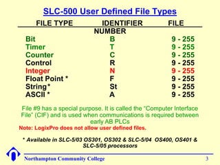
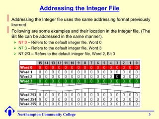
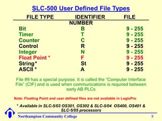
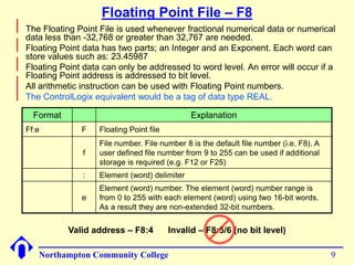
SLC500 and LogixPro 
The Integer File 
Data File #7 (N7) 
Supplement to your textbook 
Northampton Community College 1
SLC-500 Default File Types 
FILE TYPE IDENTIFIER FILE 
NUMBER 
Output O 0 
Input I 1 
Status S 2 
Bit B 3 
Timer T 4 
Counter C 5 
Control R 6 
Integer N 7 
Float Point * F 8 
* Available in SLC-5/03 OS301, OS302 & SLC-5/04 OS400, OS401 & 
SLC-5/05 processors 
Northampton Community College 2
SLC-500 User Defined File Types 
FILE TYPE IDENTIFIER FILE 
NUMBER 
Bit B 9 - 255 
Timer T 9 - 255 
Counter C 9 - 255 
Control R 9 - 255 
Integer N 9 - 255 
Float Point * F 9 - 255 
String* St 9 - 255 
ASCII * A 9 - 255 
File #9 has a special purpose. It is called the “Computer Interface 
File” (CIF) and is used when communications is required between 
early AB PLCs 
Note: LogixPro does not allow user defined files. 
* Available in SLC-5/03 OS301, OS302 & SLC-5/04 OS400, OS401 & 
SLC-5/05 processors 
Northampton Community College 3
Integer File – Data File #7 
Northampton Community College 4 
 
The Integer file is a file of 256, 16-bit words. This file can be used, as 
needed, for user storage of integer data. The default radix is decimal, 
but it can be changed to binary, octal, hex/BCD or ASCII. 
 
The ControlLogix equivalent would be a tag of data type INT
Addressing the Integer File 
Northampton Community College 5 
 
Addressing the Integer file uses the same addressing format previously 
learned. 
 
Following are some examples and their location in the Integer file. (The 
Bit file can be addressed in the same manner). 
 N7:0 – Refers to the default integer file, Word 0 
 N7:3 – Refers to the default integer file, Word 3 
 N7:2/3 – Refers to the default integer file, Word 2, Bit 3
SLC500 
Floating Point File 
Not available in LogixPro 
Data File #8 (F8) 
Supplement to your textbook 
Northampton Community College 6
SLC-500 Default File Types 
FILE TYPE IDENTIFIER FILE 
NUMBER 
Output O 0 
Input I 1 
Status S 2 
Bit B 3 
Timer T 4 
Counter C 5 
Control R 6 
Integer N 7 
Float Point * F 8 
* Available in SLC-5/03 OS301, OS302 & SLC-5/04 OS400, OS401 & 
SLC-5/05 processors 
Northampton Community College 7
SLC-500 User Defined File Types 
FILE TYPE IDENTIFIER FILE 
NUMBER 
Bit B 9 - 255 
Timer T 9 - 255 
Counter C 9 - 255 
Control R 9 - 255 
Integer N 9 - 255 
Float Point * F 9 - 255 
String* St 9 - 255 
ASCII * A 9 - 255 
File #9 has a special purpose. It is called the “Computer Interface 
File” (CIF) and is used when communications is required between 
early AB PLCs 
Note: Floating Point and user defined files are not available in LogixPro 
* Available in SLC-5/03 OS301, OS302 & SLC-5/04 OS400, OS401 & 
SLC-5/05 processors 
Northampton Community College 8
Floating Point File – F8 
Format Explanation 
Ff:e F Floating Point file 
f 
File number. File number 8 is the default file number (i.e. F8). A 
user defined file number from 9 to 255 can be used if additional 
storage is required (e.g. F12 or F25) 
: Element (word) delimiter 
e 
Element (word) number. The element (word) number range is 
from 0 to 255 with each element (word) using two 16-bit words. 
As a result they are non-extended 32-bit numbers. 
Northampton Community College 9 
 
The Floating Point File is used whenever fractional numerical data or numerical 
data less than -32,768 or greater than 32,767 are needed. 
 
Floating Point data has two parts; an Integer and an Exponent. Each word can 
store values such as: 23.45987 
 
Floating Point data can only be addressed to word level. An error will occur if a 
Floating Point address is addressed to bit level. 
 
All arithmetic instruction can be used with Floating Point numbers. 
 
The ControlLogix equivalent would be a tag of data type REAL. 
Valid address – F8:4 Invalid – F8:5/6 (no bit level)
Data Manipulation 
Chapter 06 Section 6-5-6 
Supplement to your textbook. 
Your textbook does not talk in any great detail 
about the Move (MOV) and Masked Move 
(MVM) instructions. 
Northampton Community College 10
Data Manipulation Instructions 
Northampton Community College 11 
 
Data manipulation instructions enable the programmable 
controller to manipulate data stored in memory. 
 
This extra characteristic gives the PLC capabilities that go 
far beyond the conventional relay equivalent instructions. 
 
Data manipulation involves transfer of data and operation 
on data with math functions, data conversion, data 
comparison and logical operations.
Data Files, Words and Bits 
Northampton Community College 12 
 
Words of data memory, in singular form, can be referred to 
either as registers, elements or as words, depending upon 
the PLC/PAC manufacturer. 
 
The terms table, array or file are generally used when a 
consecutive group of related data memory words is 
referenced. A group of consecutive elements or words in the 
SLC-500 family are referred to as a file, in a ControlLogix 
controller they are referred to as an array, in Siemens it is 
called a table or an array. 
 
The data contained in files and words will be in the form of 
binary bits represented as a series of 1’s and 0’s.
Data Files, Words and Bits 
Northampton Community College 13 
 
This is a pictorial representation of a file 
File, Array or Table
Data Manipulation Instructions 
Northampton Community College 14 
 
Data manipulation instructions allow the movement, 
manipulation or storage of data in either single or multiple 
word groups from one data memory area of the PLC to 
another. 
 
The use of data manipulation instructions in applications 
that require the generation and manipulation of large 
quantities of data generally reduces the complexity and 
quantity of the programming required.
Data Transfer Operations 
Northampton Community College 15 
 
Data transfer instructions simply involve the transfer of the 
contents from one word or register to another. 
 
When new data replaces existing data, the process is 
referred to as writing over the existing data. 
 
Data transfer instructions can address almost any location 
in memory. That location may be the preset word for a timer 
or counter or even an output register that controls a seven-segment 
display or a series of output devices.
Data Transfer Concept 
User defined Integer 
file N10:7 starts out 
with no data. 
After the data 
transfer occurs, 
word N10:7 will 
contain the same 
data as word 
N7:14. 
Data is to be transferred from a word in the 
default Integer file N7:14 to a word in the 
user defined Integer file N10:7. 
Northampton Community College 16
Move (MOV) Instruction 
Northampton Community College 17 
 
Allen-Bradley series controllers use a block formatted Move (MOV) 
instruction to perform data moves. 
 
The MOV instruction is an output instruction that moves the value stored 
in one word to another word. It doesn’t actually move the data, it makes 
a copy of the data from the source to the destination. 
 
The MOV instruction has two parameters: 
 Source 
 Destination 
Source specifies the 
word containing the 
data to be moved. 
Dest specifies the 
word where the data 
should be moved. 
Place holder that 
will display the 
value stored in 
these words when 
monitoring online.
Move (MOV) Instruction 
Northampton Community College 18 
 
The instruction parameters of a MOV instruction have several rules: 
 The destination (Dest) must always be a WORD level address or WORD 
level tag. 
 The Source can be a WORD level address, a WORD level tag or a program 
constant. 
 
MOV instructions can be conditional or unconditional. 
Conditional MOV 
Unconditional MOV
Move (MOV) Instruction 
Northampton Community College 19 
 
When the rung is true, the value 
stored at the Source address, N7:56, 
is Moved (copied) into the Dest 
address, C5:34.PRE. 
 
When the rung goes false, the Dest 
address will retain the value unless it 
is changed somewhere else in the 
program.
Siemens Move (MOVE) Instruction 
Northampton Community College 20 
 
When the Enable (EN) input becomes true, the data stored in the IN tag 
is moved to the OUT tag. 
 
The Enable Out (ENO) will be a logic 1 if the EN input is true and the 
MOVE occurred without error. 
 
MOVE instructions can be conditional or unconditional.
Lets Build the Following Circuit 
Northampton Community College 21 
 
You were assigned the task of implementing a new circuit that 
can be used to control a pump that is being used to pump sugar 
syrup or molasses. Because these ingredients have a different 
viscosity, the pump needs a startup delay of 10-seconds when 
pumping sugar syrup and 15-seconds when pumping molasses. 
 
Two separate latching N/O selector switches are used to select 
the correct time-delay. One for selecting the time delay for sugar 
syrup and one for selecting the time delay for molasses. The user 
should not be able to start the system if both time-delays are 
selected at the same time. 
 
Nothing should start unless the Start push button is pressed and 
everything should stop if the Stop push button is pressed. 
 
Once the Start push button is pressed, if the operator attempts to 
change the delay time, the setting should not take affect. For the 
new setting to take affect, the Stop push button must be pressed 
and the system must than be restarted. 
 
Preload the delay times into the appropriate tags before 
downloading the program.
Lets Build the Following Circuit – I/O Assignment 
 
Field device assignment: 
 Start Push Button – Wired to IN9 of the input module in slot 03 
 Stop Push Button – Wired to IN10 of the input module in slot 03 
 10-Second selector – Wired to IN4 of the input module in slot 03 
 15-Second selector – Wired to IN6 of the input module in slot 03 
 Pump motor starter – Wired to OUT7 of the output module in slot 09 
Northampton Community College 22
Circuit that Changes the Preset of a Counter with a MOV 
Northampton Community College 23
Masked Move (MVM) Instruction 
(Not in the IEC Standard) 
Northampton Community College 24 
 
The Masked Move (MVM) instruction is slightly different 
from the MOV instruction in that a mask word is involved in 
the MOV. 
 
The data being moved must pass through a mask to get to 
the Dest address. 
 
In the SLC500, the MVM instruction is used to move (copy) 
only the desired bits from a 16-bit word from the Source to 
the Dest by masking the bits that should not be moved. 
 
In the ControlLogix, the MVM instruction is used to move 
(copy) only the desired bits from a tag of data type SINT, 
INT or DINT from the Source to the Destination by masking 
the bits that should not be moved.
Masked Move (MVM) Instruction 
Northampton Community College 25 
 
The MVM instruction has three parameters: 
 Source 
 Mask 
 Dest 
 
The parameters have several rules: 
 The Source and Dest must be WORD level addresses. 
 The Mask can be a WORD level address or a program constant, preferably 
in Hexadecimal. 
Source must 
be a WORD 
level address 
Mask can be a 
hexadecimal number or 
a WORD level address 
Dest must be a WORD 
level address 
These fields 
display the 
values stored 
in the 
parameter 
addresses
Masked Move (MVM) Instruction 
Northampton Community College 26 
 
The Mask can be though of as a filter. The data in the Source word will pass 
through this filter (mask) and the value exiting the filter (mask) will be stored in 
the Dest word. 
 
Think of the mask as a plate with 16-holes (32-holes if there are 32-bits) and a 
butterfly valve in each hole; like a choke on an old style carburetor. If the valve is 
closed, nothing can get through (a zero). If the valve is open, an object can drop 
through the hole (a one). 
The valve is 
open a one (1) 
and data can 
pass through 
The valve is 
closed a zero (0) 
Data cannot 
pass through 
To the destination 
Word 
To the destination 
Word 
To the destination 
Word 
The mask shown would be: 1110000010000010 or E082h
Entering a Constant Mask Value 
Northampton Community College 27 
 
When entering the mask value as a constant it can be 
entered as a binary, octal or hexadecimal value. It is usually 
best to enter a constant as a hexadecimal number. 
 
Entering mask values as constants is done in the following 
formats: 
 
SLC500 
 Hexadecimal value: 0FFA3h 
 Octal value: 2273o 
 Binary value: 1010001100111100b 
 
ControlLogix 
 Hexadecimal value: 16#FFA37BC8 
 Octal value: 8#2273 
 Binary value: 2#101000110011100
Masked Move (MVM) Instruction 
These statement are not always true depending 
upon what version of RSLogix 500 is being used 
Northampton Community College 28 
 
The Mask can be entered as an address or tag, or as a program 
constant in hexadecimal, binary or octal. 
 
Where there is a ‘1 in the mask, data will pass from the Source to the 
Dest. Where there is a ‘0’ in the mask, data from the Source will not 
pass to the Dest. The bit positions in the Dest that are masked will retain 
whatever state they were in before the MVM occurred. 
Mask as a hex value: 7AB4h 
If the hex value starts with a letter, 
a leading ‘0’ will be added: 0AB74h 
Mask as an address: B3:16 
The value stored in B3:16 = 71CFh
Masked Move (MVM) Instruction 
1 1 0 0 1 1 0 0 1 1 0 0 1 1 0 0 Destination before the MVM 
Northampton Community College 29 
 
Mask operation example 
1 0 1 0 1 0 1 0 1 0 1 0 1 0 1 0 Source 
1 1 1 0 0 0 0 0 1 0 0 0 0 1 0 0 Mask 
1 0 1 0 1 1 0 0 1 1 0 0 1 0 0 0 Destination after the MVM
MVM Example 
Northampton Community College 30 
 
In the SLC500 MVM all 16-bits of the input module in slot 1 are being 
moved through a mask and storing the result in N7:0. 
 
The mask is “filtering out” everything except the devices wired to IN 
terminals, 4, 5, 6, 7, 8 & 11. 
 
In the ControlLogix MVM all 16-bits of the input module in slot 10 of the 
local rack are being moved through a mask and stored in the destination 
tag. 
 
The mask is “filtering out” everything except the devices wired to IN 
terminals, 0, 1, 3, 5, 12, 13, 14, 15. 
0000 
MVM 
Masked Move 
Source I:1.0 
0< 
Mask 09F0h 
2544< 
Dest N7:0 
0<
ControlLogix Masks 
DINT mask (32-bit) 
INT mask (16-bit) 
SINT mask (8-bit) 
Northampton Community College 31

11 chapter06 slc_int_float_mov_mvm_fa14

  • 1.
    SLC500 and LogixPro The Integer File Data File #7 (N7) Supplement to your textbook Northampton Community College 1
  • 2.
    SLC-500 Default FileTypes FILE TYPE IDENTIFIER FILE NUMBER Output O 0 Input I 1 Status S 2 Bit B 3 Timer T 4 Counter C 5 Control R 6 Integer N 7 Float Point * F 8 * Available in SLC-5/03 OS301, OS302 & SLC-5/04 OS400, OS401 & SLC-5/05 processors Northampton Community College 2
  • 3.
    SLC-500 User DefinedFile Types FILE TYPE IDENTIFIER FILE NUMBER Bit B 9 - 255 Timer T 9 - 255 Counter C 9 - 255 Control R 9 - 255 Integer N 9 - 255 Float Point * F 9 - 255 String* St 9 - 255 ASCII * A 9 - 255 File #9 has a special purpose. It is called the “Computer Interface File” (CIF) and is used when communications is required between early AB PLCs Note: LogixPro does not allow user defined files. * Available in SLC-5/03 OS301, OS302 & SLC-5/04 OS400, OS401 & SLC-5/05 processors Northampton Community College 3
  • 4.
    Integer File –Data File #7 Northampton Community College 4  The Integer file is a file of 256, 16-bit words. This file can be used, as needed, for user storage of integer data. The default radix is decimal, but it can be changed to binary, octal, hex/BCD or ASCII.  The ControlLogix equivalent would be a tag of data type INT
  • 5.
    Addressing the IntegerFile Northampton Community College 5  Addressing the Integer file uses the same addressing format previously learned.  Following are some examples and their location in the Integer file. (The Bit file can be addressed in the same manner).  N7:0 – Refers to the default integer file, Word 0  N7:3 – Refers to the default integer file, Word 3  N7:2/3 – Refers to the default integer file, Word 2, Bit 3
  • 6.
    SLC500 Floating PointFile Not available in LogixPro Data File #8 (F8) Supplement to your textbook Northampton Community College 6
  • 7.
    SLC-500 Default FileTypes FILE TYPE IDENTIFIER FILE NUMBER Output O 0 Input I 1 Status S 2 Bit B 3 Timer T 4 Counter C 5 Control R 6 Integer N 7 Float Point * F 8 * Available in SLC-5/03 OS301, OS302 & SLC-5/04 OS400, OS401 & SLC-5/05 processors Northampton Community College 7
  • 8.
    SLC-500 User DefinedFile Types FILE TYPE IDENTIFIER FILE NUMBER Bit B 9 - 255 Timer T 9 - 255 Counter C 9 - 255 Control R 9 - 255 Integer N 9 - 255 Float Point * F 9 - 255 String* St 9 - 255 ASCII * A 9 - 255 File #9 has a special purpose. It is called the “Computer Interface File” (CIF) and is used when communications is required between early AB PLCs Note: Floating Point and user defined files are not available in LogixPro * Available in SLC-5/03 OS301, OS302 & SLC-5/04 OS400, OS401 & SLC-5/05 processors Northampton Community College 8
  • 9.
    Floating Point File– F8 Format Explanation Ff:e F Floating Point file f File number. File number 8 is the default file number (i.e. F8). A user defined file number from 9 to 255 can be used if additional storage is required (e.g. F12 or F25) : Element (word) delimiter e Element (word) number. The element (word) number range is from 0 to 255 with each element (word) using two 16-bit words. As a result they are non-extended 32-bit numbers. Northampton Community College 9  The Floating Point File is used whenever fractional numerical data or numerical data less than -32,768 or greater than 32,767 are needed.  Floating Point data has two parts; an Integer and an Exponent. Each word can store values such as: 23.45987  Floating Point data can only be addressed to word level. An error will occur if a Floating Point address is addressed to bit level.  All arithmetic instruction can be used with Floating Point numbers.  The ControlLogix equivalent would be a tag of data type REAL. Valid address – F8:4 Invalid – F8:5/6 (no bit level)
  • 10.
    Data Manipulation Chapter06 Section 6-5-6 Supplement to your textbook. Your textbook does not talk in any great detail about the Move (MOV) and Masked Move (MVM) instructions. Northampton Community College 10
  • 11.
    Data Manipulation Instructions Northampton Community College 11  Data manipulation instructions enable the programmable controller to manipulate data stored in memory.  This extra characteristic gives the PLC capabilities that go far beyond the conventional relay equivalent instructions.  Data manipulation involves transfer of data and operation on data with math functions, data conversion, data comparison and logical operations.
  • 12.
    Data Files, Wordsand Bits Northampton Community College 12  Words of data memory, in singular form, can be referred to either as registers, elements or as words, depending upon the PLC/PAC manufacturer.  The terms table, array or file are generally used when a consecutive group of related data memory words is referenced. A group of consecutive elements or words in the SLC-500 family are referred to as a file, in a ControlLogix controller they are referred to as an array, in Siemens it is called a table or an array.  The data contained in files and words will be in the form of binary bits represented as a series of 1’s and 0’s.
  • 13.
    Data Files, Wordsand Bits Northampton Community College 13  This is a pictorial representation of a file File, Array or Table
  • 14.
    Data Manipulation Instructions Northampton Community College 14  Data manipulation instructions allow the movement, manipulation or storage of data in either single or multiple word groups from one data memory area of the PLC to another.  The use of data manipulation instructions in applications that require the generation and manipulation of large quantities of data generally reduces the complexity and quantity of the programming required.
  • 15.
    Data Transfer Operations Northampton Community College 15  Data transfer instructions simply involve the transfer of the contents from one word or register to another.  When new data replaces existing data, the process is referred to as writing over the existing data.  Data transfer instructions can address almost any location in memory. That location may be the preset word for a timer or counter or even an output register that controls a seven-segment display or a series of output devices.
  • 16.
    Data Transfer Concept User defined Integer file N10:7 starts out with no data. After the data transfer occurs, word N10:7 will contain the same data as word N7:14. Data is to be transferred from a word in the default Integer file N7:14 to a word in the user defined Integer file N10:7. Northampton Community College 16
  • 17.
    Move (MOV) Instruction Northampton Community College 17  Allen-Bradley series controllers use a block formatted Move (MOV) instruction to perform data moves.  The MOV instruction is an output instruction that moves the value stored in one word to another word. It doesn’t actually move the data, it makes a copy of the data from the source to the destination.  The MOV instruction has two parameters:  Source  Destination Source specifies the word containing the data to be moved. Dest specifies the word where the data should be moved. Place holder that will display the value stored in these words when monitoring online.
  • 18.
    Move (MOV) Instruction Northampton Community College 18  The instruction parameters of a MOV instruction have several rules:  The destination (Dest) must always be a WORD level address or WORD level tag.  The Source can be a WORD level address, a WORD level tag or a program constant.  MOV instructions can be conditional or unconditional. Conditional MOV Unconditional MOV
  • 19.
    Move (MOV) Instruction Northampton Community College 19  When the rung is true, the value stored at the Source address, N7:56, is Moved (copied) into the Dest address, C5:34.PRE.  When the rung goes false, the Dest address will retain the value unless it is changed somewhere else in the program.
  • 20.
    Siemens Move (MOVE)Instruction Northampton Community College 20  When the Enable (EN) input becomes true, the data stored in the IN tag is moved to the OUT tag.  The Enable Out (ENO) will be a logic 1 if the EN input is true and the MOVE occurred without error.  MOVE instructions can be conditional or unconditional.
  • 21.
    Lets Build theFollowing Circuit Northampton Community College 21  You were assigned the task of implementing a new circuit that can be used to control a pump that is being used to pump sugar syrup or molasses. Because these ingredients have a different viscosity, the pump needs a startup delay of 10-seconds when pumping sugar syrup and 15-seconds when pumping molasses.  Two separate latching N/O selector switches are used to select the correct time-delay. One for selecting the time delay for sugar syrup and one for selecting the time delay for molasses. The user should not be able to start the system if both time-delays are selected at the same time.  Nothing should start unless the Start push button is pressed and everything should stop if the Stop push button is pressed.  Once the Start push button is pressed, if the operator attempts to change the delay time, the setting should not take affect. For the new setting to take affect, the Stop push button must be pressed and the system must than be restarted.  Preload the delay times into the appropriate tags before downloading the program.
  • 22.
    Lets Build theFollowing Circuit – I/O Assignment  Field device assignment:  Start Push Button – Wired to IN9 of the input module in slot 03  Stop Push Button – Wired to IN10 of the input module in slot 03  10-Second selector – Wired to IN4 of the input module in slot 03  15-Second selector – Wired to IN6 of the input module in slot 03  Pump motor starter – Wired to OUT7 of the output module in slot 09 Northampton Community College 22
  • 23.
    Circuit that Changesthe Preset of a Counter with a MOV Northampton Community College 23
  • 24.
    Masked Move (MVM)Instruction (Not in the IEC Standard) Northampton Community College 24  The Masked Move (MVM) instruction is slightly different from the MOV instruction in that a mask word is involved in the MOV.  The data being moved must pass through a mask to get to the Dest address.  In the SLC500, the MVM instruction is used to move (copy) only the desired bits from a 16-bit word from the Source to the Dest by masking the bits that should not be moved.  In the ControlLogix, the MVM instruction is used to move (copy) only the desired bits from a tag of data type SINT, INT or DINT from the Source to the Destination by masking the bits that should not be moved.
  • 25.
    Masked Move (MVM)Instruction Northampton Community College 25  The MVM instruction has three parameters:  Source  Mask  Dest  The parameters have several rules:  The Source and Dest must be WORD level addresses.  The Mask can be a WORD level address or a program constant, preferably in Hexadecimal. Source must be a WORD level address Mask can be a hexadecimal number or a WORD level address Dest must be a WORD level address These fields display the values stored in the parameter addresses
  • 26.
    Masked Move (MVM)Instruction Northampton Community College 26  The Mask can be though of as a filter. The data in the Source word will pass through this filter (mask) and the value exiting the filter (mask) will be stored in the Dest word.  Think of the mask as a plate with 16-holes (32-holes if there are 32-bits) and a butterfly valve in each hole; like a choke on an old style carburetor. If the valve is closed, nothing can get through (a zero). If the valve is open, an object can drop through the hole (a one). The valve is open a one (1) and data can pass through The valve is closed a zero (0) Data cannot pass through To the destination Word To the destination Word To the destination Word The mask shown would be: 1110000010000010 or E082h
  • 27.
    Entering a ConstantMask Value Northampton Community College 27  When entering the mask value as a constant it can be entered as a binary, octal or hexadecimal value. It is usually best to enter a constant as a hexadecimal number.  Entering mask values as constants is done in the following formats:  SLC500  Hexadecimal value: 0FFA3h  Octal value: 2273o  Binary value: 1010001100111100b  ControlLogix  Hexadecimal value: 16#FFA37BC8  Octal value: 8#2273  Binary value: 2#101000110011100
  • 28.
    Masked Move (MVM)Instruction These statement are not always true depending upon what version of RSLogix 500 is being used Northampton Community College 28  The Mask can be entered as an address or tag, or as a program constant in hexadecimal, binary or octal.  Where there is a ‘1 in the mask, data will pass from the Source to the Dest. Where there is a ‘0’ in the mask, data from the Source will not pass to the Dest. The bit positions in the Dest that are masked will retain whatever state they were in before the MVM occurred. Mask as a hex value: 7AB4h If the hex value starts with a letter, a leading ‘0’ will be added: 0AB74h Mask as an address: B3:16 The value stored in B3:16 = 71CFh
  • 29.
    Masked Move (MVM)Instruction 1 1 0 0 1 1 0 0 1 1 0 0 1 1 0 0 Destination before the MVM Northampton Community College 29  Mask operation example 1 0 1 0 1 0 1 0 1 0 1 0 1 0 1 0 Source 1 1 1 0 0 0 0 0 1 0 0 0 0 1 0 0 Mask 1 0 1 0 1 1 0 0 1 1 0 0 1 0 0 0 Destination after the MVM
  • 30.
    MVM Example NorthamptonCommunity College 30  In the SLC500 MVM all 16-bits of the input module in slot 1 are being moved through a mask and storing the result in N7:0.  The mask is “filtering out” everything except the devices wired to IN terminals, 4, 5, 6, 7, 8 & 11.  In the ControlLogix MVM all 16-bits of the input module in slot 10 of the local rack are being moved through a mask and stored in the destination tag.  The mask is “filtering out” everything except the devices wired to IN terminals, 0, 1, 3, 5, 12, 13, 14, 15. 0000 MVM Masked Move Source I:1.0 0< Mask 09F0h 2544< Dest N7:0 0<
  • 31.
    ControlLogix Masks DINTmask (32-bit) INT mask (16-bit) SINT mask (8-bit) Northampton Community College 31