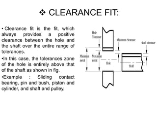
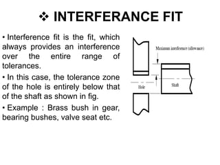
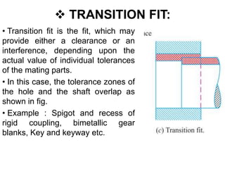
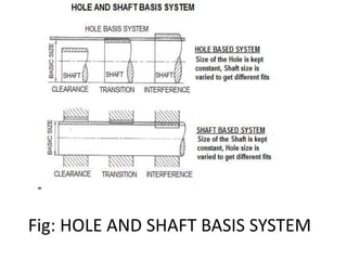
Subject :- MACHINE DESIGN AND INDUSTRIAL DRAFTING
Subject code: 2141907
Topic :- LIMITS AND FITS
•Made By :-
-PATEL VISHAL _160993119017_MDID
-PRAJAPATI HIMANSHU_160093119018_MDID
- TAILOR VISHAL _160093119019_MDID
- VANATH RAJVEER_160993119020_MDID
-VASAVA ANJAL_160993119021_MDID
-Guided By :-
-Mr. Rudra Parmar
 CONTENT
• LIMITS
• FITS
LIMITS
• The two extreme permissible size of a given
dimension are known as limits.
• MAXIMUM SIZE LIMIT: The greater of the two
extreme permissible sizes is known as Maximum
Limit.
• MINIMUM SIZE LIMIT: The smaller of the two
extreme permissible sizes is known as Minimum
limit.
• For example, for a shaft with basic size of 30 mm,
let the permissible variation in the diameter is
between 29.93mm and 30.05mm. Hence
maximum size limit = 30.05mm and minimum size
limit= 29.93mm
 FITS
• Dimensional tolerances deal with the permissible
variations in the dimension of a component.
• However, when the two components are to be assembled,
it is important to relate the dimensions of these two
components to be assembled (i.e, shaft and hole)
• The difference between the dimensions of the two
components to be assembled is very important form the
point of view of assembly as well as the performance of
the machine.
• FITS: When two parts ( Hole and Shaft) are assembled the
type of assembly resulting by virtue of the difference
between their sizes before assembly is called a fit.
 Types of Fits:
• Depending upon the relative sizes of the hole and shaft,
the fits are broadly classified into three types:
1. Clearance Fit
2. Interference Fit
3. Transition Fit
 CLEARANCE FIT:
• Clearance fit is the fit, which
always provides a positive
clearance between the hole and
the shaft over the entire range of
tolerances.
•In this case, the tolerances zone
of the hole is entirely above that
of the shaft as shown in fig.
•Example : Sliding contact
bearing, pin and bush, piston and
cylinder, and shaft and pulley.
 INTERFERANCE FIT
• Interference fit is the fit, which
always provides an interference
over the entire range of
tolerances.
• In this case, the tolerance zone
of the hole is entirely below that
of the shaft as shown in fig.
• Example : Brass bush in gear,
bearing bushes, valve seat etc.
 TRANSITION FIT:
• Transition fit is the fit, which may
provide either a clearance or an
interference, depending upon the
actual value of individual tolerances
of the mating parts.
• In this case, the tolerance zones of
the hole and the shaft overlap as
shown in fig.
• Example : Spigot and recess of
rigid coupling, bimetallic gear
blanks, Key and keyway etc.
 SYSTEMS OF FITS
• There are two types basic systems of fits:
1. Hole Basis System
2. Shaft Basis System
 HOLE BASIS SYATEM
• In hole basis system, as shown in fig. the size of the hole
is the basic size, whose lower deviation is zero. The
clearance and interference are obtained by associating
various shaft diameters.
• The hole basis system is advantageous, because
normally holes are machined by standard drills and
reams and their dimensions are fixed.
• Examples of holes basis system: 50H7-g8, 30H7-k6
Fig: HOLE AND SHAFT BASIS SYSTEM
• SHAFT BASIS SYSTEM:
• In shaft basis system, as shown in fig., the size of the
basic size whose upper deviation is zero.
• The clearances and interferences are obtained by
associating various hole diameters.
• The hole basis system is useful, where shafts are made
from standard bright bars.
• Example of shaft basis system: 50G8-h7, 30K8-h7.
Limits and fits (machine design & industrial drafting )

Limits and fits (machine design & industrial drafting )

  • 1.
    Subject :- MACHINEDESIGN AND INDUSTRIAL DRAFTING Subject code: 2141907 Topic :- LIMITS AND FITS •Made By :- -PATEL VISHAL _160993119017_MDID -PRAJAPATI HIMANSHU_160093119018_MDID - TAILOR VISHAL _160093119019_MDID - VANATH RAJVEER_160993119020_MDID -VASAVA ANJAL_160993119021_MDID -Guided By :- -Mr. Rudra Parmar
  • 2.
  • 3.
    LIMITS • The twoextreme permissible size of a given dimension are known as limits. • MAXIMUM SIZE LIMIT: The greater of the two extreme permissible sizes is known as Maximum Limit. • MINIMUM SIZE LIMIT: The smaller of the two extreme permissible sizes is known as Minimum limit. • For example, for a shaft with basic size of 30 mm, let the permissible variation in the diameter is between 29.93mm and 30.05mm. Hence maximum size limit = 30.05mm and minimum size limit= 29.93mm
  • 4.
     FITS • Dimensionaltolerances deal with the permissible variations in the dimension of a component. • However, when the two components are to be assembled, it is important to relate the dimensions of these two components to be assembled (i.e, shaft and hole) • The difference between the dimensions of the two components to be assembled is very important form the point of view of assembly as well as the performance of the machine. • FITS: When two parts ( Hole and Shaft) are assembled the type of assembly resulting by virtue of the difference between their sizes before assembly is called a fit.
  • 5.
     Types ofFits: • Depending upon the relative sizes of the hole and shaft, the fits are broadly classified into three types: 1. Clearance Fit 2. Interference Fit 3. Transition Fit
  • 6.
     CLEARANCE FIT: •Clearance fit is the fit, which always provides a positive clearance between the hole and the shaft over the entire range of tolerances. •In this case, the tolerances zone of the hole is entirely above that of the shaft as shown in fig. •Example : Sliding contact bearing, pin and bush, piston and cylinder, and shaft and pulley.
  • 7.
     INTERFERANCE FIT •Interference fit is the fit, which always provides an interference over the entire range of tolerances. • In this case, the tolerance zone of the hole is entirely below that of the shaft as shown in fig. • Example : Brass bush in gear, bearing bushes, valve seat etc.
  • 8.
     TRANSITION FIT: •Transition fit is the fit, which may provide either a clearance or an interference, depending upon the actual value of individual tolerances of the mating parts. • In this case, the tolerance zones of the hole and the shaft overlap as shown in fig. • Example : Spigot and recess of rigid coupling, bimetallic gear blanks, Key and keyway etc.
  • 9.
     SYSTEMS OFFITS • There are two types basic systems of fits: 1. Hole Basis System 2. Shaft Basis System  HOLE BASIS SYATEM • In hole basis system, as shown in fig. the size of the hole is the basic size, whose lower deviation is zero. The clearance and interference are obtained by associating various shaft diameters. • The hole basis system is advantageous, because normally holes are machined by standard drills and reams and their dimensions are fixed. • Examples of holes basis system: 50H7-g8, 30H7-k6
  • 10.
    Fig: HOLE ANDSHAFT BASIS SYSTEM
  • 11.
    • SHAFT BASISSYSTEM: • In shaft basis system, as shown in fig., the size of the basic size whose upper deviation is zero. • The clearances and interferences are obtained by associating various hole diameters. • The hole basis system is useful, where shafts are made from standard bright bars. • Example of shaft basis system: 50G8-h7, 30K8-h7.