Introduction
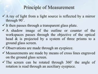
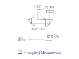
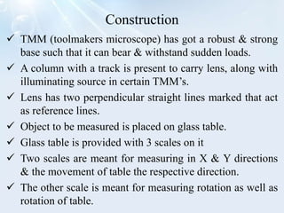
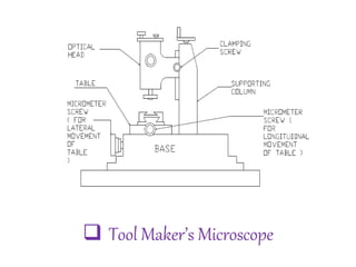
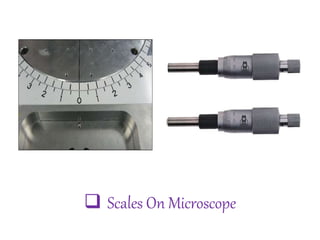
 The toolmaker's microscope is an optical measuring
machine equipped for external & internal length
measurements as well as measurements on screw threads,
profiles, curvatures & angles.
 A toolmakers microscope is a measuring device that can
be used to measure up to 1/100th of an mm.
 It works on the principle of a screw gauge, but a few
changes were added to it to make its operation more
easier.
 It needs application of optics too.
 A light focuses on the object & through lens we can see
the shadow of the object, which resembles the object.
 More clear shadow would be enhance the accuracy of
measurement.
Principle of Measurement
 A ray of light from a light source is reflected by a mirror
through 90˚.
 It then passes through a transparent glass plate.
 A shadow image of the outline or counter of the
workspaces passes through the objective of the optical
head & is projected by a system of three prisms to a
ground glass screen.
 Observations are made through an eyepiece.
 Measurements are made by means of cross lines engraved
on the ground glass screen.
 The screen can be rotated through 360˚ the angle of
rotation is read through an auxiliary eyepiece.
 Principle of Measurement
Construction
 TMM (toolmakers microscope) has got a robust & strong
base such that it can bear & withstand sudden loads.
 A column with a track is present to carry lens, along with
illuminating source in certain TMM’s.
 Lens has two perpendicular straight lines marked that act
as reference lines.
 Object to be measured is placed on glass table.
 Glass table is provided with 3 scales on it
 Two scales are meant for measuring in X & Y directions
& the movement of table the respective direction.
 The other scale is meant for measuring rotation as well as
rotation of table.
 Tool Maker’s Microscope
 Scales On Microscope
Working
• The component being measured is illuminated by the
through light method.
• A parallel beam of light illuminates the lower side of
work-piece which is then received by the objective lens in
its way to a prism that deflects the light rays in the
direction of the measuring ocular & the projection screen.
• The direction of illumination can be tilted with respect to
the work-piece by tilting the measuring head & the whole
optical system.
• This inclined illumination is necessary in some cases as in
screw thread measurements.
Application
 Length measurement in Cartesian & polar co-ordinates.
 Angle measurements of tools.
 Thread measurements i.e., profile major & minor
diameters, height of lead, thread
 angle, profile position with respect to the thread axis & the
shape of thread.
 Comparison between centers & drawn patterns & drawing
of projected profiles.
 Used for measuring the shape of different components like
the template, formed cutter, milling cutter, punching die,
and cam
Tool makers microscope

Tool makers microscope

  • 4.
    Introduction  The toolmaker'smicroscope is an optical measuring machine equipped for external & internal length measurements as well as measurements on screw threads, profiles, curvatures & angles.  A toolmakers microscope is a measuring device that can be used to measure up to 1/100th of an mm.  It works on the principle of a screw gauge, but a few changes were added to it to make its operation more easier.  It needs application of optics too.  A light focuses on the object & through lens we can see the shadow of the object, which resembles the object.  More clear shadow would be enhance the accuracy of measurement.
  • 5.
    Principle of Measurement A ray of light from a light source is reflected by a mirror through 90˚.  It then passes through a transparent glass plate.  A shadow image of the outline or counter of the workspaces passes through the objective of the optical head & is projected by a system of three prisms to a ground glass screen.  Observations are made through an eyepiece.  Measurements are made by means of cross lines engraved on the ground glass screen.  The screen can be rotated through 360˚ the angle of rotation is read through an auxiliary eyepiece.
  • 6.
     Principle ofMeasurement
  • 7.
    Construction  TMM (toolmakersmicroscope) has got a robust & strong base such that it can bear & withstand sudden loads.  A column with a track is present to carry lens, along with illuminating source in certain TMM’s.  Lens has two perpendicular straight lines marked that act as reference lines.  Object to be measured is placed on glass table.  Glass table is provided with 3 scales on it  Two scales are meant for measuring in X & Y directions & the movement of table the respective direction.  The other scale is meant for measuring rotation as well as rotation of table.
  • 8.
  • 9.
     Scales OnMicroscope
  • 10.
    Working • The componentbeing measured is illuminated by the through light method. • A parallel beam of light illuminates the lower side of work-piece which is then received by the objective lens in its way to a prism that deflects the light rays in the direction of the measuring ocular & the projection screen. • The direction of illumination can be tilted with respect to the work-piece by tilting the measuring head & the whole optical system. • This inclined illumination is necessary in some cases as in screw thread measurements.
  • 11.
    Application  Length measurementin Cartesian & polar co-ordinates.  Angle measurements of tools.  Thread measurements i.e., profile major & minor diameters, height of lead, thread  angle, profile position with respect to the thread axis & the shape of thread.  Comparison between centers & drawn patterns & drawing of projected profiles.  Used for measuring the shape of different components like the template, formed cutter, milling cutter, punching die, and cam