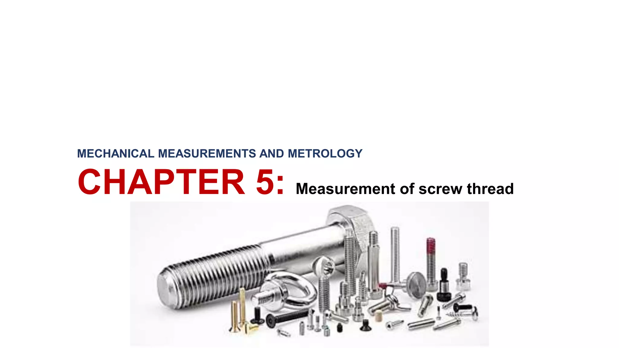
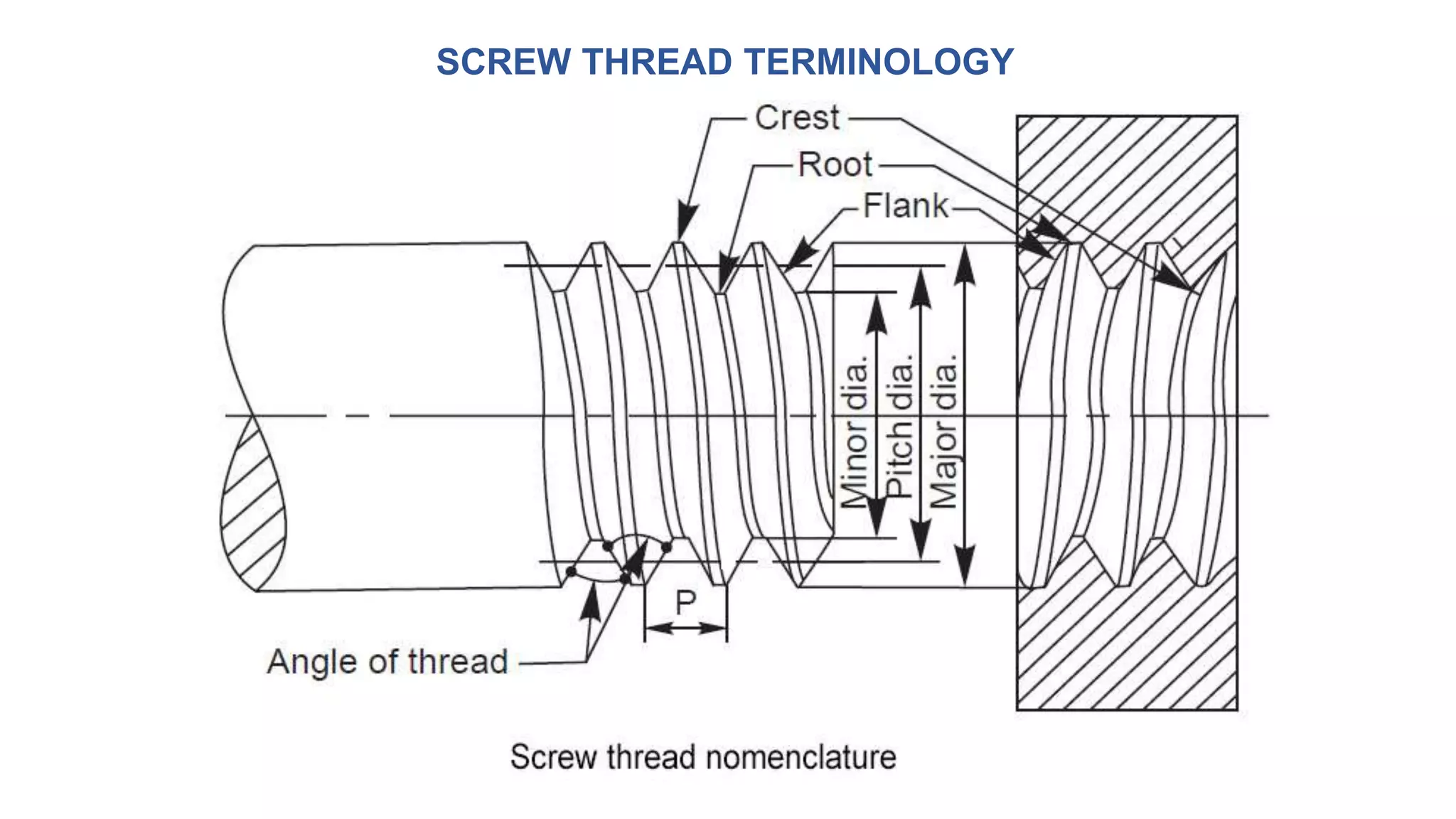
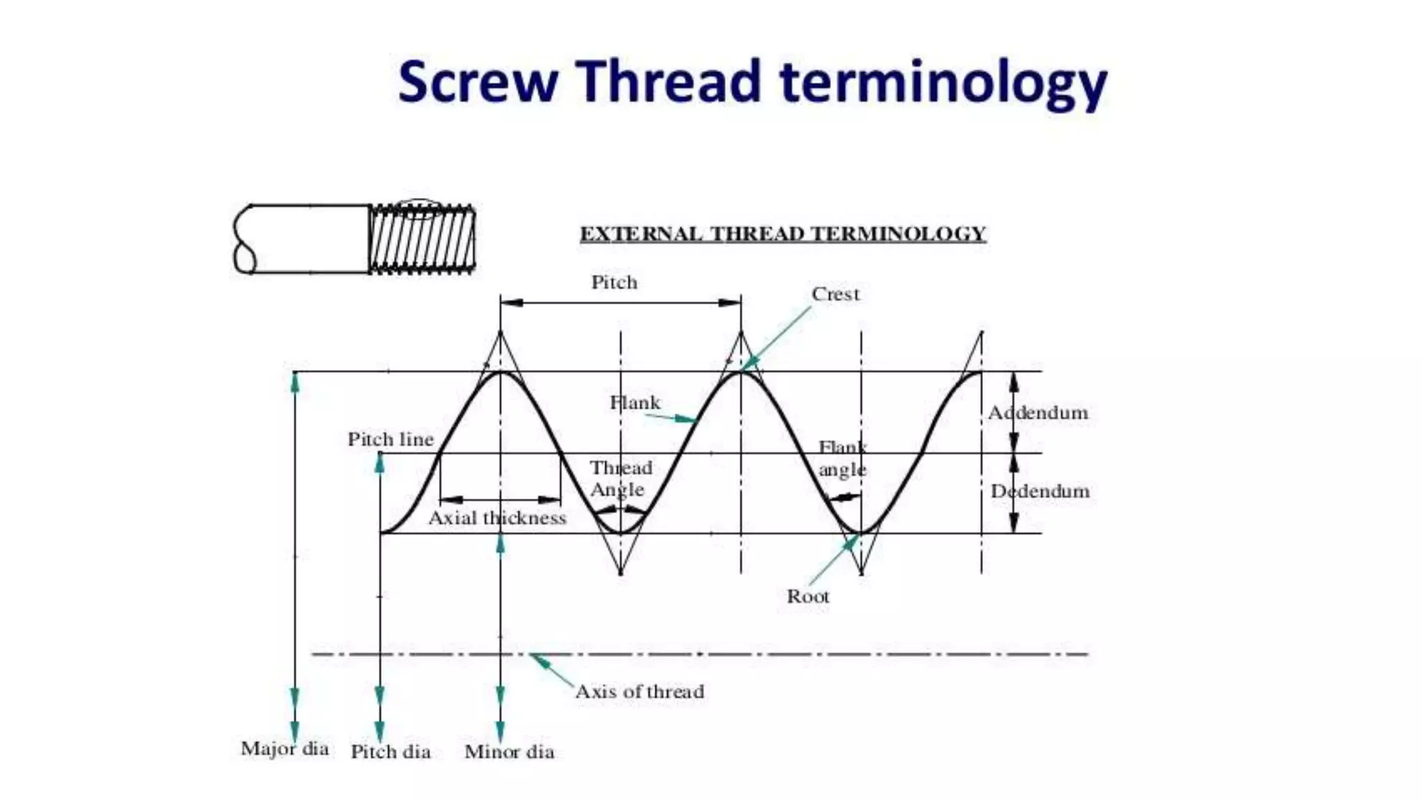
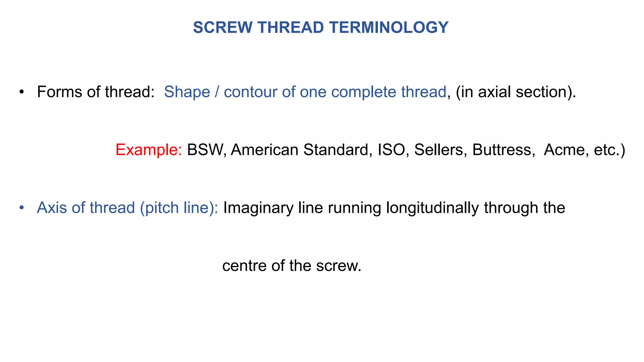
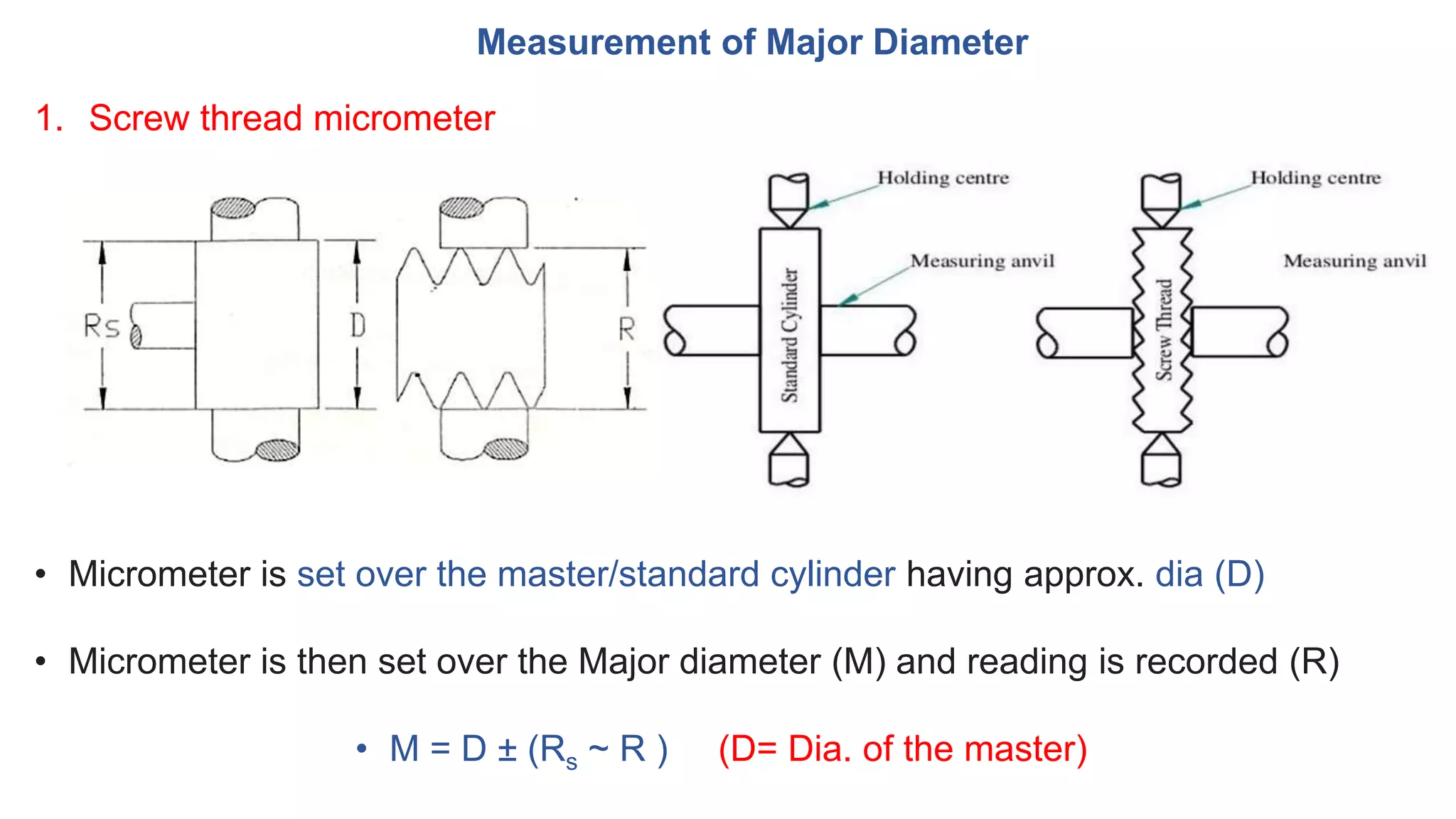
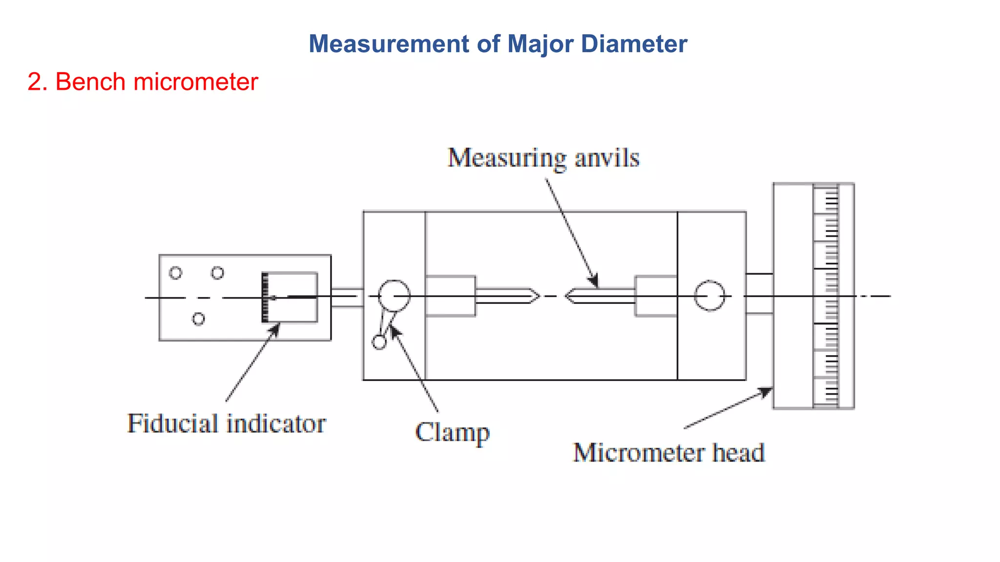
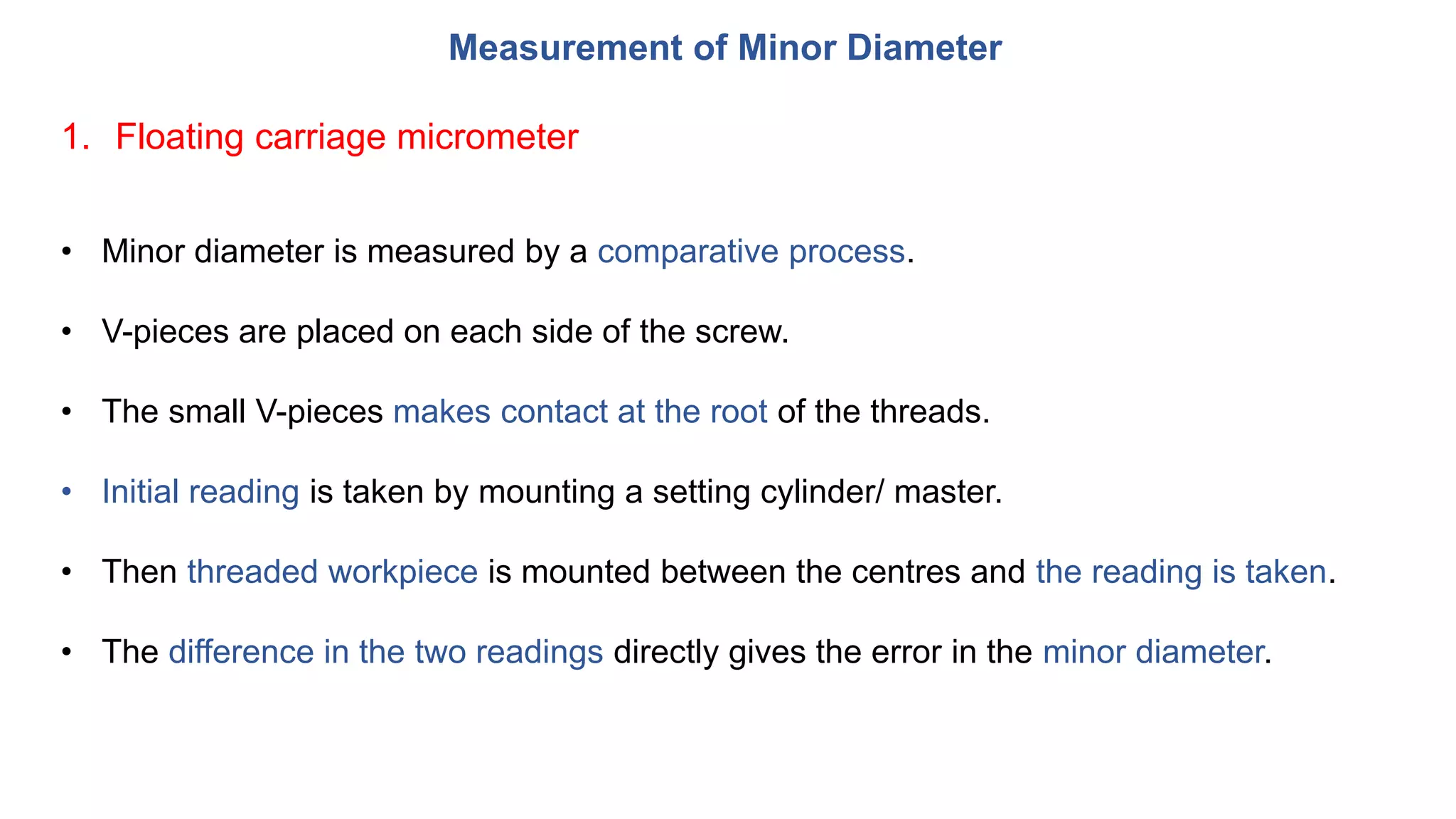
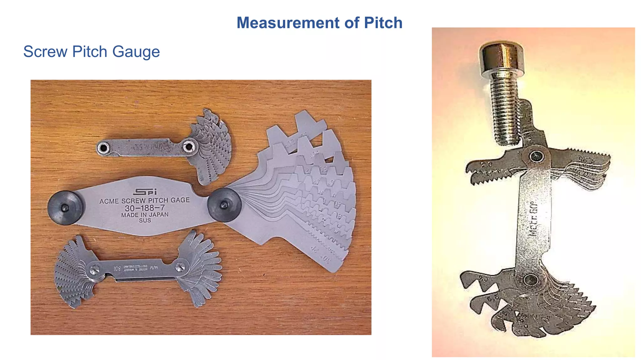
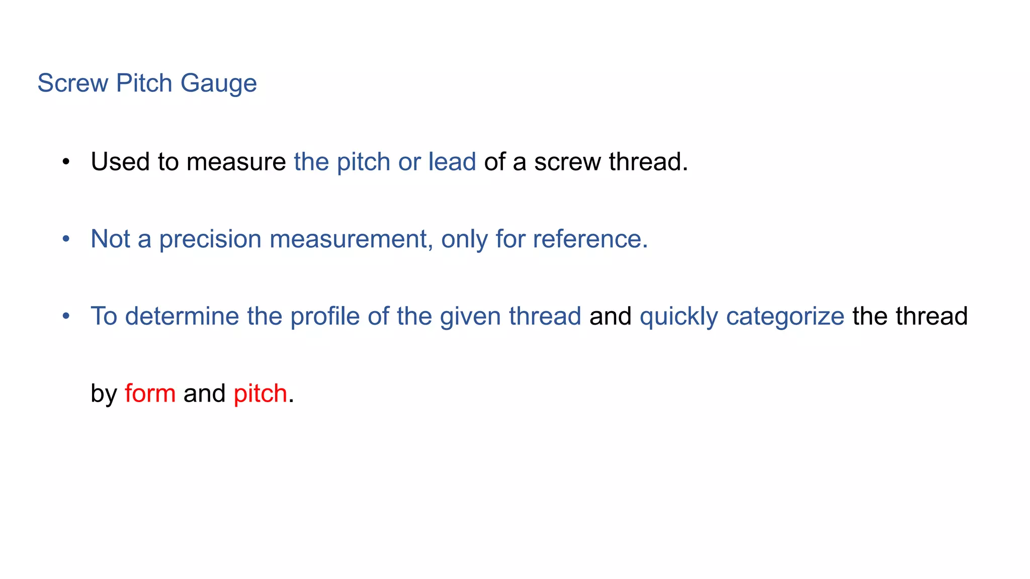
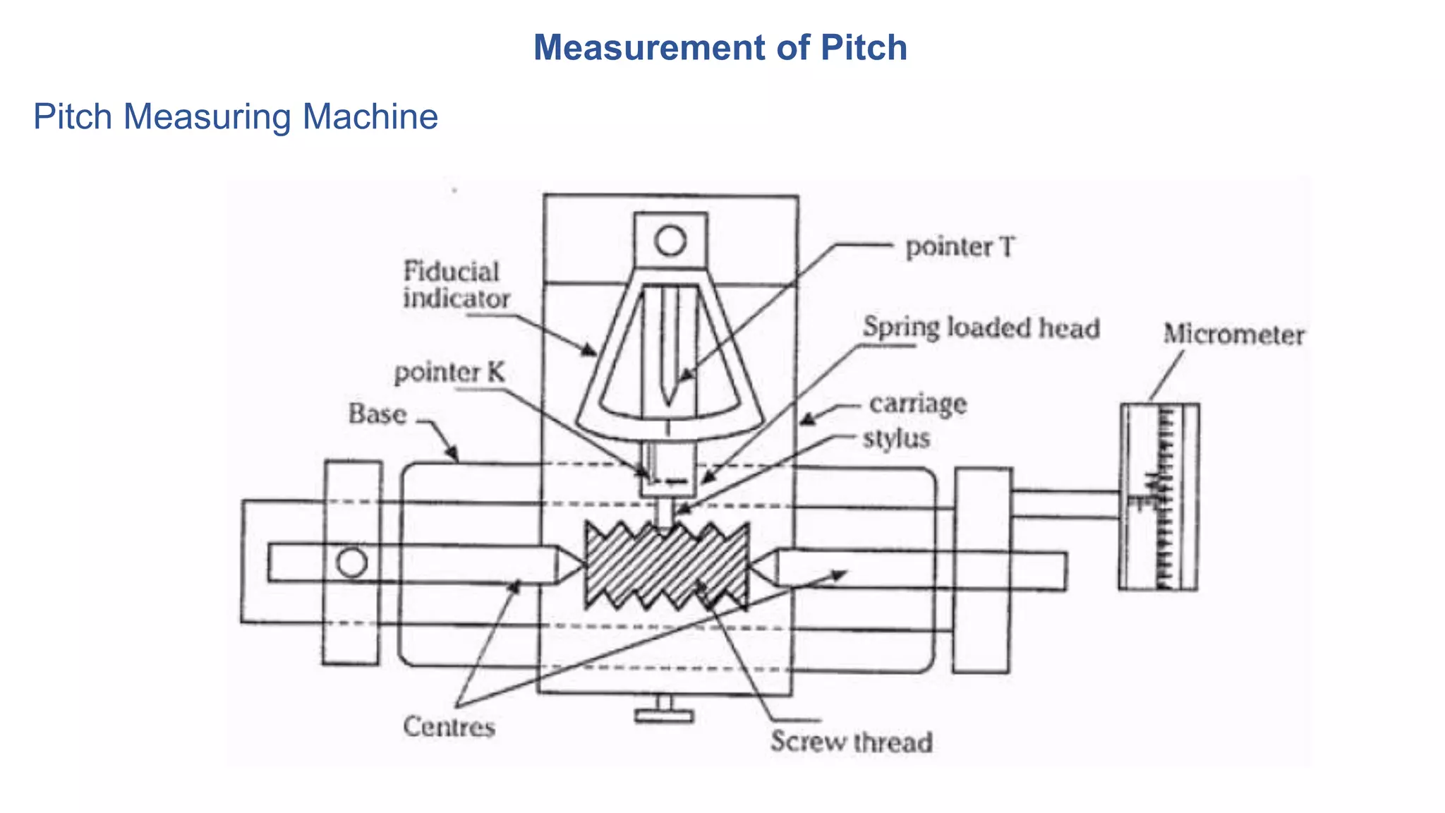
The document discusses measurement and metrology of screw threads. It begins with definitions of screw thread terminology such as major diameter, minor diameter, pitch, angle, and forms of threads. It then describes methods for measuring the major diameter, minor diameter, effective diameter, and pitch of screw threads. The key measurement methods discussed are using micrometers, pitch gauges, and a tool maker's microscope. The goal is to understand principles and techniques for measuring characteristics of screw threads.
Surface roughness metrology deals with basic terminology of surface,surface roughness indication methods,analysis of surface traces, measurement methods,surface roughness measuring instruments such as Stylus Probe Instrument, Profilometer, Tomlinson Surface Meter ,The Taylor-Hobson Talysurf etc.This is very useful for diploma,degree engineering students of mechanical,production,automobile branch
Unit 2 Machinability, Cutting Fluids, Tool Life & Wear, Tool MaterialsMechbytes
Concept of machinability, machinability index, factors affecting machinability
Different mechanism of tool wear types of tool wear (crater, flank etc.), Measurement and control of tool wear
Concept of tool life, Taylor's tool life equation (including modified version)
Different tool materials and their applications including effect of tool coating
Introduction to economics of machining
Cutting fluids: types, properties, selection and application methods
Introduction to Mechanical Measurements and Metrology taruian
Introduction to Metrology: Definition, objectives of metrology, Material Standards, Wavelength Standards, Classification of standards, Line and End standards, Calibration of End bars. Numerical examples.
This presentation gives the information about Screw thread measurements and Gear measurement of the subject: Mechanical measurement and Metrology (10ME32/42) of VTU Syllabus covering unit-4.
Dynamo meters are the electronic devices that are widely used to the purpose of force analysis in various field of operations. There is various types of dynamometers such as
Lathe tool dynamometer
Milling tool dynamometer
Drilling tool dynamometer
unit I
Introduction and Basic Concepts: Introduction, Objectives, classification and principles of
surveying, Scales, Shrinkage of Map, Conventional symbols and Code of Signals, Surveying
accessories, phases of surveying.
Measurement of Distances and Directions
Linear distances- Approximate methods, Direct Methods- Chains- Tapes, ranging, Tape corrections.
Prismatic Compass- Bearings, included angles, Local Attraction, Magnetic Declination and dip.
Test for straightness by using spirit level and Autocollimator
The straightness of any surface could be determined by either of these instruments by measuring the relative angular positions of number of adjacent sections of the surface to be tested. First straight line is drawn on the surface then it is divided into a number of sections the length of each section being equal to the length of sprit level base or the plane reflector’ s base in case of auto collimator. The bases of the spirit level block or reflector are fitted with two feet so that only feet have line contact with the surface and the surface of base does not touch the surface to he tested. The angular division obtained is between the specified two points. Length of each section must be equal to distance between the centerlines of two feet. The special level can be used only for the measurement of straightness of horizontal surfaces while auto-collimator can be used on surfaces are any plane. In case of spirit level, the block is moved along the line equal to the pitch distance between the centerline of the feet and the angular variation of the direction of block. Angular variation can be determined in terms of the difference of height between two points by knowing the least count of level and length of the base.
Introduction_Medical Robotics
Types of medical robots - Navigation - Motion Replication - Imaging - Rehabilitation and Prosthetics - State of art of robotics in the field of healthcare
Introduction to OS
Basic Principles, Operating System Structures, System Calls & Types, Processes: Concept Scheduling - Inter
Process Communication, Introduction to Distributed Operating System, Types of network based OS.
Robot Drives And End Effectors
Robot drive systems: Hydraulic, Pneumatic and Electric drive
systems, classification of end effectors, mechanical grippers, vacuum grippers, magnetic grippers,
adhesive gripper, gripper force analysis and gripper design
Robot Anatomy And Motion Analysis
Anatomy of a Robot, Robot configurations: polar, cylindrical,
Cartesian, and jointed arm configurations, Robot links and joints, Degrees of freedom: types of
movements, vertical, radial and rotational traverse, roll, pitch and yaw, Wok volume/envelope, Robot
kinematics: Introduction to direct and inverse kinematics, transformations and rotation matrix
Avoiding Risk & Harmful Habits
Characteristics of health compromising behaviors, Recognizing and avoiding of
addictions, How addiction develops, Types of addictions, influencing factors of addictions, Differences between addictive
people and non addictive people & their behaviors. Effects of addictions
Creating Healthy & Caring Relationships
Building communication skills, Friends and friendship - Education,
the value of relationship and communication skills, Relationships for Better or worsening of life, understanding of basic
instincts of life (more than a biology), Changing health behaviours through social engineering
Building Healthy Life Style for Better Future.pptxtaruian
Building Healthy Life Style for Better Future
Developing healthy diet for good health, Food & health, Nutritional
guidelines for good health, Obesity & overweight disorders and its management, Eating disorders, Fitness components for
health, Wellness and physical function, How to avoid exercise injuries
Good Health & It’s balance for positive mindset.pptxtaruian
Health -Importance of Health, Influencing factors of Health,
Health beliefs, Advantages of good health, Health & Behavior, Health & Society, Health & family, Health & Personality,
Psychological disorders-Methods to improve good psychological health, Changing health habits for good health
Thread terminology, sectional views of threads. ISO Metric (Internal & External), BSW (Internal & External), Square and Acme, Sellers thread, American Standard thread.
IoT Processing Topologies and Types: Data Format, Importance of Processing in IoT, Processing Topologies, IoT Device Design and Selection Considerations, Processing Offloading.
Introduction to IoT (Basics of Networking & Emergence of IoT).pptxtaruian
Basics of Networking: Introduction, Network Types, Layered network models.
Emergence of IoT: Introduction, Evolution of IoT, Enabling IoT and the Complex Interdependence of Technologies, IoT Networking Components.
Hierarchical Digital Twin of a Naval Power SystemKerry Sado
A hierarchical digital twin of a Naval DC power system has been developed and experimentally verified. Similar to other state-of-the-art digital twins, this technology creates a digital replica of the physical system executed in real-time or faster, which can modify hardware controls. However, its advantage stems from distributing computational efforts by utilizing a hierarchical structure composed of lower-level digital twin blocks and a higher-level system digital twin. Each digital twin block is associated with a physical subsystem of the hardware and communicates with a singular system digital twin, which creates a system-level response. By extracting information from each level of the hierarchy, power system controls of the hardware were reconfigured autonomously. This hierarchical digital twin development offers several advantages over other digital twins, particularly in the field of naval power systems. The hierarchical structure allows for greater computational efficiency and scalability while the ability to autonomously reconfigure hardware controls offers increased flexibility and responsiveness. The hierarchical decomposition and models utilized were well aligned with the physical twin, as indicated by the maximum deviations between the developed digital twin hierarchy and the hardware.
Explore the innovative world of trenchless pipe repair with our comprehensive guide, "The Benefits and Techniques of Trenchless Pipe Repair." This document delves into the modern methods of repairing underground pipes without the need for extensive excavation, highlighting the numerous advantages and the latest techniques used in the industry.
Learn about the cost savings, reduced environmental impact, and minimal disruption associated with trenchless technology. Discover detailed explanations of popular techniques such as pipe bursting, cured-in-place pipe (CIPP) lining, and directional drilling. Understand how these methods can be applied to various types of infrastructure, from residential plumbing to large-scale municipal systems.
Ideal for homeowners, contractors, engineers, and anyone interested in modern plumbing solutions, this guide provides valuable insights into why trenchless pipe repair is becoming the preferred choice for pipe rehabilitation. Stay informed about the latest advancements and best practices in the field.
1. Department of Mechanical Engineering
JSS Academy of Technical Education, Bangalore-560060
MECHANICAL MEASUREMENTS AND METROLOGY
(Course Code:18ME36B)
2. TEXT BOOKS
• Mechanical Measurements, Beckwith Marangoni and Lienhard, Pearson Education, 6th Ed., 2006.
• Instrumentation, Measurement and Analysis, B C Nakra, K K Chaudhry, 4th Edition, McGraw Hill.
• Engineering Metrology, R.K. Jain, Khanna Publishers, Delhi, 2009
REFERENCE BOOKS:
• Engineering Metrology and Measurements, N.V.Raghavendra and L.Krishnamurthy, Oxford
University Press..
Further Reference:
National Programme on Technology Enhanced Learning (NPTEL)
http://nptel.ac.in/courses/112104121/1
5. Explain the measurement principles of major diameter, minor diameter, effective
diameter, pitch, angle, and form of screw threads.
Outcomes
6. Module 2
• Terminology of screw threads, Measurement of major diameter, Minor diameter,
Pitch, Angle
• Effective diameter of screw threads by;
• 2-wire
• 3-wire methods.
• Best size wire.
• Screw thread gauges
• Tool maker’s microscope
7. SCREW THREAD TERMINOLOGY
Definition (Screw thread)
As per American Society of Tool and Manufacturing Engineers (ASTME)
• Screw thread is the helical ridge produced by forming a continuous helical groove
of uniform section on the external or internal surface of a cylinder.
11. SCREW THREAD TERMINOLOGY
• Forms of thread: Shape / contour of one complete thread, (in axial section).
Example: BSW, American Standard, ISO, Sellers, Buttress, Acme, etc.)
• Axis of thread (pitch line): Imaginary line running longitudinally through the
centre of the screw.
12. SCREW THREAD TERMINOLOGY
• Angle of thread: Angle between the flanks of a thread (Also called as included
angle.)
• Flank angle: Angle formed between a flank of the thread and the perpendicular to
the axis of the thread.
• Fundamental triangle: Imaginary triangle formed when the flanks are extended, till
they meet each other to form apex.
13. SCREW THREAD TERMINOLOGY
• Pitch: Distance between two corresponding crest or root.
• Lead: The axial distance moved by the screw, when the screw is given one
complete revolution.
14. SCREW THREAD TERMINOLOGY
• Major (nominal) diameter: The largest diameter of a screw thread.
• Minor (core) diameter: The smallest diameter of a screw thread.
• Pitch diameter / Effective diameter: The imaginary diameter of a cylinder, passing
through the threads at the points where the thread width is equal to the space
between the threads.
15. Measurement of Major Diameter
Measurement of a major diameter by;
1. Screw thread micrometer (Comparator)
2. Bench micrometer
16. Measurement of Major Diameter
1. Screw thread micrometer
• Micrometer is set over the master/standard cylinder having approx. dia (D)
• Micrometer is then set over the Major diameter (M) and reading is recorded (R)
• M = D ± (Rs ~ R ) (D= Dia. of the master)
18. Measurement of Major Diameter
2. Bench micrometer
• Designed to remove the deficiencies of the hand micrometer.
• Fiducial micrometer ensures the readings are taken with uniform pressure.
• Used as a comparator.
• Procedure is same as of ordinary micrometer.
19. Measurement of Minor Diameter
Measurement of a minor diameter by;
1. Floating carriage micrometer
20. Measurement of Minor Diameter
1. Floating carriage micrometer
• M = D ± (Rs ~ R ) (D= Dia. of the master)
21. Measurement of Minor Diameter
1. Floating carriage micrometer
• Minor diameter is measured by a comparative process.
• V-pieces are placed on each side of the screw.
• The small V-pieces makes contact at the root of the threads.
• Initial reading is taken by mounting a setting cylinder/ master.
• Then threaded workpiece is mounted between the centres and the reading is taken.
• The difference in the two readings directly gives the error in the minor diameter.
22. Measurement of Effective Diameter
• A notional value.
• Cannot be measured directly.
• An indirect approach to be followed i.e. (Measurement by wire method)
Principle
• Small, hardened steel wires (best-size wire) are placed in the groove and the
distance over them is measured as part of the measurement process.
23. Measurement of Effective Diameter
There are three methods of using wires:
• One-wire method
• Two-wire method
• Three-wire methods.
24. Measurement of Effective Diameter
Two-wire method
In this method, two steel wires of identical diameter are placed on opposite
flanks of a screw, as shown in Fig.
• First the micrometer reading is taken over the standard.
• The standard is replaced by the screw thread and the reading is recorded.
• Difference between reading over the standard and the screw thread is taken as a
measurement of Effective diameter.
Pitch line
25. Measurement of Effective Diameter
Two-wire method
T = M − 2d
M= Dimension over wires
d = diameter of the best-size wire
Effective diameter (E); E = T + P
T = Dimension under the wires
P = Correction factor
P depends on diameter of wire, pitch and thread angle
‘P’ value can be calculated from the following formula;
P = 0.86602 X p (ISO & Unified)
P = 0.96049 X p = 1.16568 x d (BSW)
Where, p = Pitch
d = mean diameter of wires used.
P = Difference between effective dia and dia under the wires.
26. Two-wire method If the size of the wire contacts the flanks at the pitch
line, it is called the best size wire, can be determined
by the geometry of screw thread;
27. Best Wire Size
If the size of the wire contacts the flanks at the pitch line, called the best size
wire, determined by the geometry of screw thread.
P
28. Best Wire Size
P
Half of thread angle =
𝜃
2
From triangle OAP, Sin POA =
𝐴𝑃
𝑂𝑃
or
Sin (90 -
𝜃
2
) =
𝐴𝑃
𝑂𝑃
Wire diameter = 2r
Best Wire diameter = Db = 2r = 2AP sec
𝜃
2
29. Best Wire Size
P
Since AP lies on the pitch line
AP =
𝑃
4
Best Wire diameter = Db =
𝑃
2
sec
𝜃
2
30. Measurement of Effective Diameter
Diameter of Best-size Wire
• The best size wire to be selected as recommended in IS 6311.
‘P’ value can be calculated from the following formula;
• P = 0.86602 X p (ISO & Unified)
• P = 0.96049 X p =1.16568 x d (BSW)
Where p = Pitch
d = mean diameter of wires used.
31. Measurement of Effective Diameter
Three-wire method
• M = Distance over the wires
• E = Effective diameter
• d = diameter of best-size wires
• H = height of threads
32. Measurement of Effective Diameter
Three-wire method
h = is the height of the centre of wire from the pitch line.
h = OC − BC.
33. Measurement of Effective Diameter
Three-wire method
Distance over wires, M = E + 2h + 2r
r = radius of the wires
Therefore, effective diameter
35. • Used to measure the pitch or lead of a screw thread.
• Not a precision measurement, only for reference.
• To determine the profile of the given thread and quickly categorize the thread
by form and pitch.
Screw Pitch Gauge
37. Measurement of Pitch
Pitch Measuring Machine
• Position the stylus between the flanks of the
thread along the pitch line.
• Ensure the fiducial indicator reads 0.
• Record the initial reading.
• Move the stylus into the adjacent flank and
record the reading.
• Difference between the two readings is taken
as a measurement of pitch.
38. Tool Maker’s Microscope
• A versatile instrument that, applies the principle of optics.
It is designed for measurements of;
• Complex forms / Profiles.
• Distance between the centres.
• Linear measurements & Angular measurements.
41. Tool Maker’s Microscope
• A light from a source (fig.) is reflected by a mirror through 90°.
• It passes through a transparent glass plate.
• A shadow or profile of the workpiece passes through the objective lens of the
optical head
• It is projected by system of three prisms to a glass screen.
• Measurements are made by means of cross lines engraved on the ground
glass screen.
• The screen can be rotated through 360.
Principle